1987 is considered the time of creation of the iconic and recognizable connector, called “Video Graphics Adapter” or “VGA” for short. Until 1998, this standard had virtually no noticeable competitors.
Sometimes this “old man” can surprise you by supporting a resolution of 2048x1536. But you can’t look at the image without tears...
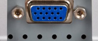
Externally, it is a trapezoidal port with fifteen holes for contacts. It can only process analog video, like older TVs. Due to limited data transfer capabilities, VGA did not allow achieving high-quality images on the monitor. This became especially noticeable with the advent of high-resolution screens - the “picture” was blurry and had incorrect colors. The quality was also determined by the length of the cable - the longer it was, the less worthy the result the user received.
The DVI interface that replaced VGA showed better results, but could not reach the top of another hero of our article - HDMI. Externally, it looks like a smaller and flatter version of the USB connector. Unlike its "wild ancestors", it works with a digital signal to transmit information. This allows you to broadcast a higher quality image of any resolution to the monitor.
This standard is already firmly established in multimedia products. And he's really cool!
NOTE!
A special advantage of the digital interface is the ability to transfer sound files and play them. Total savings, isn't it?!
Data interfaces
Any technology has I/O ports in its design. For ease of use, connectors are installed in the device housings. Depending on the type of signal being transmitted, they can be digital or analog.
The signal, regardless of its nature, represents electromagnetic disturbances of various shapes and frequencies. Depending on what type of vibration is transmitted, the device receiving this signal processes it and generates a signal that can be perceived. The analog transmission code has a continuous waveform, and the digital code has a discrete waveform.
The disadvantages of the analog form of transmission include: the signal is noisy due to its strong perception of interference and poor security. At the same time, the digital signal has a quality that is several orders of magnitude higher and is practically unaffected by interference and has high security due to the encryption algorithms used.
A special device is used to convert one type of signal into another. A device that changes the analog type of signal to a digital one is called an analog-to-digital converter (ADC), and conversely, a device that performs the opposite function is called a digital-to-analog converter (DAC). It is important to understand that a simple cord with VGA and HDMI connectors at the ends will not work, since due to the difference in the nature of the signals, an active converter will be required.
Analog port
With the development of computer technology, IBM introduced the VGA video interface into its devices in 1978. The use of an analog signal made it possible to reduce the number of conductors in the cable and improve color image transmission. The first generation interface was called XGA, but was eventually replaced by SVGA. Having undergone minor changes, it was able to transmit a signal in higher resolution. The connector and cable of this standard used did not change for more than ten years, until digital technologies replaced analog ones.
The VGA connector is a 15-pin device. VGA, broadcasting the signal, changes its voltage level line by line, which corresponds to a change in the brightness and intensity of the beam. The connector pinout looks like this :
- RED - used to transmit red color in the signal.
- GREEN - used to transmit green color in the signal.
- BLUE - used to transmit blue color in the signal.
- ID 2/RES - backup channel.
- GND - common channel.
- RED_RTN — red screen.
- GREEN_RTN — green screen.
- BLUE_RTN - blue screen.
- KEY/PWR - used as a key or to transmit +5 volt DC voltage.
- GND - common channel.
- D0/RES - zero bit.
- D1/SDA is the first.
- HSync - designed for horizontal synchronization.
- VSync - designed for vertical synchronization.
- D3/SCL - third bit.
By the beginning of 2010, VGA became obsolete and was replaced by DVI and HDMI digital interfaces. For compatibility, some of the lines in the new connectors were VGA interfaces.
Digital port
The most used digital interfaces are HDMI and DVI. The difference between them is the transmission standard. In 1999, the Digital Display Working Group developed the concept of digital signal broadcasting. And then, the Silicon Image company developed algorithms that allow sequential transmission of data, which were used to create the DVI format.
In early 2008, the DVI standard began to be replaced by new specifications. It was replaced by the HDMI standard. Due to the fact that their specifications are fully compatible, active converters are not required to establish a connection between them, but only an electrical connection of the contacts is sufficient.
High Definition Multimedia Interface (HDMI) is a format for transmitting various types of signals used in high-definition multimedia. The connector itself is small in size and has recently completely replaced other types of interfaces. The origin of the standard was the union of the largest giant manufacturers of multimedia equipment: Silicon Image, Matsushita Electric Industrial, Sony, Philips, Hitachi. The HDMI port consists of 19 pins and comes in different form factors: HDMI, mini and micro.
The HDMI cable pinout is as follows:
- Using pins one through nine, TMDS data is transferred. This data may contain both video and audio. Each channel contains a high and low signal level and a surge suppressor.
- Pins 10 to 12 transmit TMDS synchronization pulses. Similarly, the first nine contain signals of different levels and a limiter.
- The thirteenth pin is used to transmit control data.
- The fourteenth pin is not used.
- Pins 15 and 16 are data display channels.
- Pin 17 serves to limit the level of control channels.
- Pin 18 is used to broadcast stabilized five volts.
- Using pin 19 allows you to connect without disconnecting the device.
The throughput of the standard reaches 48 Gbit/s, and the length of the cable transmitting the signal without attenuation is 10 meters. When using active amplifiers, the transmission distance increases to 35 meters, while the amplifying device is located closer to the receiving equipment. The HDMI cable contains :
- Protective shell.
- The screen is made of copper braid with a single core for soldering.
- Aluminum foil screen.
- Twisted pairs, each with external insulation and shielding, correspond to the fifth category. The conductor channel resistance is 100 Ohms.
- Unshielded twisted pair cables for low speed peripheral components.
- Conductors for transmitting control and power.
The latest generation of HDMI, being backwards compatible with DVI, allows you to transmit a signal in resolution up to 1080p with eight channels of digital audio in one cable.
The HDMI interface is used to connect various devices, for example: video consoles, DVD players, various types of receivers, computers with TVs using a digital signal.
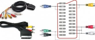
Wiring of cables for YUV (Y/PbCb/PrCr), VGA HD15, DVI, HDMI, s-Video, SCART (Peritel, Euroconnector) signals.
VGA HD15 connector pins
| Cont. | Signal | Description |
| 1 | RED | Channel R (red) (75 ohms, 0.7 V) |
| 2 | GREEN | Channel G (green) (75 ohms, 0.7 V) |
| 3 | BLUE | Channel B (blue) (75 ohms, 0.7 V) |
| 4 | ID2 | ID bit 2 |
| 5 | GND | Earth |
| 6 | RGND | R channel ground |
| 7 | GGND | G channel ground |
| 8 | BGND | Channel Ground B |
| 9 | KEY | No contact (key) |
| 10 | SGND | Earth Sync |
| 11 | ID0 | ID bit 0 |
| 12 | ID1 or SDA | ID bit 1 or DDC data |
| 13 | HSYNC or CSYNC | Linear or composite synchronization |
| 14 | VSYNC | Frame synchronization |
| 15 | ID3 or SCL | ID bit 3 or DDC clocks |
Wiring of cable Kramer BC5x5S (5-coaxial)
Standard connectors on other systems only have the pins needed to make the connection. The kind where if you touch two probes, it beeps to indicate the connection. Hot glue. Don't leave without it. Small, thin flathead screwdrivers, large flathead screwdriver.
- A small pair of tweezers.
- Metal pliers, tin snips, something like that.
- Soldering iron.
- Multimeter with circuit testing capability.
Okay, let's go for this sucker.
Making your own VGA cable
Insert a small, thin screwdriver into the seam shown in the photo above. Make a few more test tubes like this next to each other, then insert a large screwdriver as shown below. Screw it on and the body should float up nicely.
- Press inside and towards the label to go around the inner lip.
- As soon as you break the lip, you should hear a crack.
- You're coming in!
Then insert a large screwdriver into the seam next to the main cable and screw the housing in place.
Now you can remove the bottom part of the plastic and then pull the guts out of the top part. Kramer BC3x2T7S cable wiring (3-coaxial, presentation)
Wiring out the YUV signal (Y/PbCb/PrCr) from the VGA HD15 connector (for Kramer VP-41 4(xl), VP-419xl, VP-420, VP-421, VP-724xl, VP-728, VP-729 scalers, VP-730, VP-731, VP-725xl, VP-727, VP-747)
What are the most important factors when choosing a video cable?
Now lift the metal up and straight away from the optical audio jack and bend it to the right side as shown below.
You can now pull the bulk of the protective metal away from the rest of the socket. Remove the protective sheath free from the main cable using your metal cutters. Now you need to come across a piece of material that looks amazing, like electrical tape. Remove it and the nest should now look like the photo below. Next we need to remove the PCB from the metal. You can remove the tabs using a desoldering iron, or insert your small screwdriver under the board and lift it up as you heat the tabs with a regular iron.
DVI-I/DVI-D connector pins
| Cont. | Signal | Signal (Russian) |
| 1 | TMDS DATA 2- | TMDS data 2- |
| 2 | TMDS DATA 2+ | TMDS 2+ data |
| 3 | TMDS DATA 2/4 SHIELD | Screen for TMDS 2 and 4 data |
| 4 | TMDS DATA 4- | TMDS data 4- |
| 5 | TMDS DATA 4+ | TMDS 4+ data |
| 6 | DDC CLOCK | DDC clocks |
| 7 | DDC DATA | DDC data |
| 8 | ANALOG VERT. SYNC | Analog Frame Sync. |
| 9 | TMDS DATA 1- | TMDS data 1- |
| 10 | TMDS DATA 1+ | TMDS data 1+ |
| 11 | TMDS DATA 1/3 SHIELD | Screen for TMDS 1 and 3 data |
| 12 | TMDS DATA 3- | TMDS data 3- |
| 13 | TMDS DATA 3+ | TMDS 3+ data |
| 14 | +5V POWER | Power supply +5 V |
| 15 | GND | Earth |
| 16 | HOT PLUG DETECT | Hot Plug Sensor |
| 17 | TMDS DATA 0- | TMDS data 0- |
| 18 | TMDS DATA 0+ | TMDS data 0+ |
| 19 | TMDS DATA 0/5 SHIELD | Screen for TMDS data 0 and 5 |
| 20 | TMDS DATA 5- | TMDS data 5- |
| 21 | TMDS DATA 5+ | TMDS 5+ data |
| 22 | TMDS CLOCK SHIELD | Screen for TMDS clocks |
| 23 | TMDS CLOCK+ | TMDS+ ticks |
| 24 | TMDS CLOCK- | TMDS clocks - |
| C1 | ANALOG RED | Analog channel R |
| C2 | ANALOG GREEN | Analog channel G |
| C3 | ANALOG BLUE | Analog channel B |
| C4 | ANALOG HORZ SYNC | Analog horizontal sync. |
| C5 | ANALOG GROUND | Analog ground |
HDMI connector contacts (Single Link, Type A, up to version 1.4 inclusive)
Once the PCB is detached from the tabs, you can unplug the small connector from it and pull it out of the main unit. Finally, take a thin screwdriver and insert it between the black plastic and the thin top screen as shown below.
- Pull the metal a little and you should be able to pull the black plug out of the shielding.
- Be sure to save this piece of screen for later.
With the adhesive removed, you can remove all the wires from the plug.
Simply heat the solder on each wire until it becomes free. At this time you should put some fresh new solder on each of the pins. This will make it easier to connect new wires. The numbering may look a little strange, but it refers to how the connections are labeled on the 360 motherboard. Notice how each pin is long or short, and almost every other pin goes to ground.
| Cont. | Signal | Signal (Russian) |
| 1 | TMDS DATA 2+ | TMDS 2+ data |
| 2 | TMDS DATA 2 SHIELD | Screen for TMDS 2 data |
| 3 | TMDS DATA 2- | TMDS data 2- |
| 4 | TMDS DATA 1+ | TMDS data 1+ |
| 5 | TMDS DATA 1 SHIELD | Screen for TMDS data 1 |
| 6 | TMDS DATA 1- | TMDS data 1- |
| 7 | TMDS DATA 0+ | TMDS data 0+ |
| 8 | TMDS DATA 0 SHIELD | Screen for TMDS data 0 |
| 9 | TMDS DATA 0- | TMDS data 0- |
| 10 | TMDS CLOCK+ | TMDS+ ticks |
| 11 | TMDS CLOCK SHIELD | Screen for TMDS clocks |
| 12 | TMDS CLOCK- | TMDS clocks - |
| 13 | CEC | Consumer Electronics Control Network |
| 14 | Utility | Used for HEAC (Ethernet and Audio Return Channel) |
| 15 | DDC CLOCK | DDC clocks |
| 16 | DDC DATA | DDC data |
| 17 | DDC/CEC GND | Ground for DDC and CEC |
| 18 | +5V POWER | Power supply +5 V |
| 19 | HOT PLUG DETECT | Hot Plug Sensor |
S-Video connector pins (YC, S-VHS)
Requires purchasing multiple parts but is more useful in the long run. You'll also need left and right audio cables, as well as a yellow cable if you still like to use a composite video signal. The main connections you'll need are Red, Green, Blue, Horizontal Sync, and Vertical Sync. The selector switch has 3 wires on it. The switch can now "align" one of these two connections to establish video mode. But the new one is quite cheap and easy to use. 2 position switches if you want the box to switch modes.
- As shown at the beginning of this article.
- You only need this if you want the cable to switch modes.
- Peel off the main cover to expose the wires inside.
- They may or may not be color coded.
- Free - This saves you money on something that doesn't exist.
- This is a screw-in-screw type that is often used under the motherboard.
- Some drills.
Remove the main metal shielding to reveal the individual shielded wires inside.
Standard 4-pin MiniDIN connector
7-pin MiniDIN connector (found in ATI video cards, etc.)
10-pin connector (on ATI All-In-Wonder video cards)
| Cont. They are perfect for internal wiring of the compartment. Cut each wire to 6 inches long, now we can cut them shorter as needed. Start by sliding down some shields and stripping the end of the inner wire. Apply a little solder to it to hold all the strands together - this is called "tinning" and will make it easier to solder it to the connector. You can also put some solder at the end of the shielding to prevent it from coming off. Red Composite Video Horizontal Sync Right Audio - Shielding is not significant. Optical audio data - use a regular thin wire for this. . Step 3 - Set the ports in your notebook. When the wires are soldered to the connector, we can get a self-diagnosis box. | Signal | Description |
| 1 | C | Channel C (Color) |
| 2 | S/PDIF ground | S/PDIF Signal Ground |
| 3 | SPDIF | SPDIF signal (digital audio) |
| 4 | GND | Earth |
| 5 | GND | Earth |
| 6 | R | Audio, right channel |
| 7 | GND | Earth audio |
| 8 | Y | Channel Y (Brightness+sync) |
| 9 | V | Composite video |
| 10 | L | Audio, left channel |
10-pin connector (in Matrox G450 video cards, etc.)
Place the connector on the box lid and trace it with the tip of a knife. . Project box lid with trapezoidal connector hole. The center three pin connectors are also provided when you attach it to the main connector.
- Insert the connector through the hole and see how it fits.
- Their space is uniform.
- This way you know they will have plenty of room inside.
- Disconnect the optical audio port from the small circuit board from the connector.
Business end of the optical audio port.
Drill a hole between the optical port and the audio ports that will match the selector switch shaft. Place the pieces of the box together as shown in the picture and start by connecting the optical port. Mix the halves together, arranging the wires as you go to make sure everything fits. Once you enter the "Control Panel", go to the "System Blade" and click on "Console Settings" and "Display". Now you can select the resolution and aspect ratio according to your screen. 360 works best with widescreen displays, although you can still get it to work with square monitors. Oddly enough, it will write to the game while the toolbar and message bars take up the entire screen. Strange, right?
- Of course, be careful not to cover the 3 pins of the switch.
- Cut the wires as short as possible so it's easy to fit everything into the box.
- Wrap the case - you're done!
- If not, go to the Troubleshooting section.
You've followed all the instructions, but something isn't quite right - is it by chance one of the following?
| Cont. | Signal | Description |
| 1 | C (s-video) | Channel C (Color) |
| 2 | GND | Earth |
| 3 | Y | Channel Y (Brightness+sync) |
| 4 | RGB switching control | Control signal |
| 5 | Composite sync | Composite sync output |
| 6 | GND | Earth |
| 7 | V | Composite video |
| 8 | L | Audio, left channel |
| 9 | GND | Earth |
| 10 | R | Audio, right channel |
SCART connector pins (Peritel, Euroconnector)
Mini VGA connector pinout
Now we bet you're very glad you haven't hit all the connections in the hot bite yet - right? If you see some imagery on the screen, you probably don't have enough shielding. Make sure you have ground, 5V pins and data connected to the connector correctly.
- Check that pins 20 and 24 are connected correctly.
- Andy Warhol's inverted colors.
- Make sure all screens are connected to ground somewhere.
Depending on the signal condition, sometimes it may work, sometimes it may not.
| Cont. | Signal | Description | Level | |
| 1 | AOR | Audio output, right | 0.5 V rms | |
| 2 | AIR | Audio input, right | 0.5 V rms | >10 kOhm |
| 3 | AOL | Audio output, left + mono | 0.5 V rms | |
| 4 | AGND | Audio Ground | ||
| 5 | B GND | Ground for RGB Blue | ||
| 6 | AIL | Audio input, left + mono | 0.5 V rms | >10 kOhm |
| 7 | B | RGB Blue input | 0.7 V | 75 Ohm |
| 8 | SWTCH | Input, switching TV mode, depending on the type of TV - Audio/RGB/16:9, sometimes turning on AUX (old TVs) | 10-12 V | |
| 9 | G GND | Earth RGB Green | ||
| 10 | CLKOUT | Data 2: Clockpulse Out, only in older VCRs | ||
| 11 | G | RGB Green input | 0.7 V | 75 Ohm |
| 12 | DATA | Data 1: data output | ||
| 13 | R GND | Earth RGB Red | ||
| 14 | DATAGND | Ground for Data, remote control, only in older VCRs | ||
| 15 | R | RGB Red Input or Channel C Input | R: 0.7 V; C: 0.3 V | 75 Ohm |
| 16 | BLNK | Blanking Signal input, TV mode switching (composite/RGB), “fast” signal (new TVs) | RGB=1-3 V; Comp=0-0.4 V | 75 Ohm |
| 17 | VGND | The land of composite video | ||
| 18 | BLNKGND | Ground Blanking Signal (for pin 8 or 16) | ||
| 19 | VOUT | Composite video output | 1 V | 75 Ohm |
| 20 | VIN | Composite video input or Y (luminance) channel | 1 V | 75 Ohm |
| 21 | S.H.I.E.L.D. | Protective screen/housing |
| Prev. |
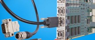
VGA and DVI connectors are used to transmit video images to digital devices, usually a video card-monitor; recently they have also become widespread in laptops for connecting to external monitors or TVs, as well as in complex medical systems.
A reliable solution is to loop the handshake lines when they are not in use. We have specifically chosen to use a personal computer as the reference frame for the signals on this page. Specific requirements for different equipment may vary.
VGA connector pinout
The first thing to remember is that there are two possibilities that you are trying to combine will actually work if you can install the cable correctly. If you have another way to prove this - for example, by trying each of the devices on a different system - do it.
| DVI pinout |
DVI is an interface standard and a corresponding connector used to transmit video images to digital display devices such as LCD monitors, televisions and projectors.
Since the signal transmitted via a DVI cable is digital and does not require double conversion, the maximum length of the cable used should not exceed 5 meters.
Before turning on both devices, turn off one of them. Then disconnect the connected device and connect the disconnected cable without otherwise rearranging the cables. Typically other cabling problems are related to communication lines. Our core business is the design of industrial electronics - most of which are sequentially controlled or networked.
To display information on the monitor, your computer sends a signal to the monitor. The signal can be in analog or digital format. However, computers operate in the digital world. The computer and video adapter convert digital data into analog format. A video adapter is an expansion card or component that provides the ability to convert displayed information into a signal that is sent to the monitor. It can also be called a graphics adapter, video card, or graphics card.
The DVI video interface can be of two types: 24-pin and 29-pin.
DVI-D 24-pin is designed for a digital interface. Its pins receive only a digital code
DVI-I 29-pin connector also supports analog signal transmission
The VGA connector is an outdated analog interface, developed in 1987 and intended for connecting analog monitors, but is still used today.
The cable connects on the back of the computer to an analog connector with 15 pins in three rows. On a regular TV, all these signals are combined into one composite video signal. There is no need to convert data from digital information to analog information. However, analog signal processing technology has improved over the years, and the difference in quality is now minimal.
The transmitter on the video adapter sends digital information to the receiver on the monitor. This gives you the option to connect a monitor that accepts a digital input or an analog input. If your video adapter only has an analog connection, find a monitor that supports analog.
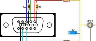
VGA - Transmits three signals: chrominance, luminance, and sync. Its pinout and purpose of each pin:
Knowing the pinout of these connectors, you can easily solder a DVI-VGA or VGA-DVI adapter.
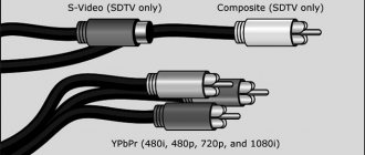
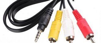
Composite video input/output (RCA), this is an analog video input-output, is widely used in video equipment as a universal means of switching. Often called "Asian" or "Tulip". Almost two separate coaxial connectors, they can be seen on the back of almost any VCR, TV, DVD player. The standard is purely analog and transmits a standard composite video signal. The main advantage of the interface is its simplicity and low cost. Color and brightness signals are transmitted over a single wire. This does not allow achieving a very clear image, so the actual resolution is around 250 -280 lines. The maximum cable length can be 20-30 meters.
The adapter can be made with male or female connectors and can stretch up to 50 feet. The second pin is attached to the green wire, and the third is used for the blue one. Pins 6, 7 and 8 act as the ground of each color channel and should be connected to the orange, green and blue striped color wires respectively.
The functions of pins in electrical connectors, whether power or signal related, must be specified in order for the connectors to be interchangeable. When connected, each pin of a connector must be in contact with a pin of another connector that has the same function. If pins of disparate functions are allowed to come into contact, the connection may fail and damage may occur.
These connectors may be present in a PC on a video card or an internal TV tuner board for receiving and transmitting an analog signal, for sending a picture to the screen of a regular TV, for recording the generated video signal to a VCR, for transmitting a signal from an analog video source to a video capture card.
S-Video (or S-VHS), another analog connector now widely used in video equipment. The chrominance and brightness signals travel through separate wires and do not interfere with each other at all. Therefore, an image with a resolution of 400-500 lines can be obtained
Signal conversion devices
To convert digital signals into analog and vice versa, special devices such as a converter are used. When choosing the right adapter from VGA to HDMI or a reverse HDMI-VGA cable, first of all, attention is paid to the operating resolution at the input and output of the device and the screen refresh rate at this resolution.
Read also: How to make a snowmobile from a moped
HDMI-VGA adapter
The peculiarity of this conversion is that, along with converting video from digital to analog, it will be necessary to transmit the audio signal in a separate path.
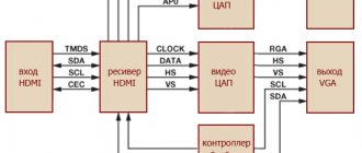
The adapter must first of all ensure the transfer of information about the display used to the high-definition signal source. This information is contained in the middle of the transmission device. Since the digital stream contains Audio and Video signals, the HDMI output device must provide auxiliary information containing the audio mode, video mode and color standard type. The HDMI receiver decrypts the received data stream and transforms it into any color format YCbCr 4:4:4, YCbCr 4:2:2, RGB 4:4:4, according to the requirements of the DAC.
After the data stream is initially processed, it is decoded and sent to the pixel bus, and then to the DAC and audio codecs. The RGB pixel bus and unsynchronized pulses form the video DAC. The clock signals are output to a data buffer and from there directly to the analog display.
The audio signal may be encoded using different compression methods, so additional processing may be required to extract it. Therefore, it is important to generate an EDID, which is extracted using an algorithm from the VGA device via the DDC information transmission channel. The obtained data must be processed and checked for the possibility of using high-frequency modes.
The processor is used to perform complex operations such as EDID readings, HDMI Rx programming and audio DAC. Due to the fact that the video DAC does not have I2C or SPI, it will not need to be controlled.
Thus, making an HDMI-VGA adapter with your own hands is not so easy. This will require knowledge not only in the field of electronics, but also in programming. The simplest adapter will consist of an HDMI receiver, a digital-to-analog converter, an audio codec, and a control microcontroller.
Considering that the price of a factory-made adapter is low, even if you find a circuit and buy the required radio elements, there will be no benefit in terms of price and labor costs. The easiest way is to purchase a ready-made adapter at a large store.
VGA-HDMI converter
The VGA to HDMI adapter also cannot be made by simply connecting the contacts. Conversion requires the presence of an active video converter. With the help of such a converter, it is easy to connect VGA signal sources to the latest panels using their HDMI input. Such converters are produced with a power supply designed for a constant voltage of five volts. In some models, power is provided via a USB cable.
The VGA-HDMI converter, in addition to video, must also transmit an audio signal. Such devices do not require settings and work immediately when turned on . Their circuitry contains: a VGA receiver, an analog-to-digital converter, an audio converter, and a control microcontroller.
Using an adapter
Quite often you can find various types of devices in everyday life, both old generation and those manufactured using the latest technologies. For example, monitors or TVs with only a VGA connector, digital consoles or set-top boxes with HDMI connectors. Just so that they can be combined for common work, signal converters are used.
It happens that there is an unused monitor with an analog input in the house, so by connecting a set-top box with T2 to it, you can get a TV. So, before connecting the monitor to a digital TV set-top box, you will need to decide what is required for this. In addition to a monitor with a VGA input and a T2 set-top box with a digital output, you will need :
- HDMI-VGA converter;
- HDMI-HDMI cable;
- VGA-VGA cable (if it is not built into the monitor itself);
- stereo wire with 3.5 jack on both ends (for sound transmission);
- columns.
The connection itself is easy. To do this, first connect the monitor to the 15-pin VGA input on the converter. The input may be designated as D-Sub. Next, the hdmi output of the set-top box is connected with an HDMI-HDMI cable to the digital input of the converter. All devices are connected to a power outlet, and then a signal from the digital set-top box should appear on the monitor screen. If the tuner settings perhaps set the maximum resolution and frequency, this primarily depends on the capabilities of the monitor. Then the audio wire is connected to the output of the Audio converter and the speaker system.
Instead of a set-top box, you can use, for example, a tablet or smartphone with an HDMI output. In this case, the device may even have a broken sensor. By connecting the gadget via an adapter to the monitor, while adding a USB remote control or Bluetooth keyboard, you can get a home multimedia entertainment center. For this purpose, there are specially developed programs for both Android and Windows systems. One of the most popular Kodi, which allows you to watch IPTV, movies, photos, torrents and more.
Invert converters from VGA to HDMI are not so popular, but can be used, for example, to connect an old computer to an LSD panel or a surveillance system built on an analog signal.
Content:
Users often need to connect two different connectors that transmit video. This usually concerns interfaces with different signals: one supports analog, and the other supports digital.
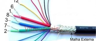
HDMI cable pinout by color
The HDMI cable is divided into 5 groups of 3 cores. And 4 more wires go separately. The connector provides switching of four groups of shielded symmetrical circuits for transmitting digital video signals (aluminum foil shield), separate wires for service data and power.
| Contact number | Purpose | Wire color | Note |
| 1 | Video signal 2+ | White | Red group |
| 2 | Video signal 2 screen | Screen | |
| 3 | Video signal 2- | Red | |
| 4 | Video signal 1+ | White | Green group |
| 5 | Video signal 1 screen | Screen | |
| 6 | Video signal 1- | Green | |
| 7 | Video signal 0+ | White | Blue group |
| 8 | Video signal 0 screen | Screen | |
| 9 | Video signal 0- | Blue | |
| 10 | Tact + | White | |
| 11 | Tact screen | Screen | |
| 12 | Tact - | Brown | |
| 13 | CEC Signal | White | |
| 14 | Utility | White | Yellow group |
| 15 | Asymmetric bus signal SCL | Orange | |
| 16 | Asymmetric bus SDA signal | Yellow | |
| 17 | Earth | Screen | Yellow group |
| 18 | Power supply +5 V | Red | |
| 19 | Connection detector | Yellow | Yellow group |
There is no single color marking for cores and each cable manufacturer may have its own marking. This is exactly what was used in the test HDMI cable.
Interfaces
HDMI is a high definition multimedia interface. It is used to transmit video and audio signals. Most modern equipment has built-in HDMI: AV, electronics, computers and many others. The interface is reliable and future-proof because electronics manufacturers closely support it.
Video Graphics Array is a video interface that was used in monitors and graphics cards before the advent of HDMI. First released in 1987, the interface is outdated but still found on analog monitors. Despite its age, VGA is capable of supporting resolutions higher than FullHD, although the image will be fuzzy and blurry.
How to create a VGA-HDMI cable with your own hands
In some situations, a person is left with two unused cables for such different video interfaces. If you have a soldering iron and, again, certain qualifications in electronics, you can also save a certain amount of money and make a full-fledged data converter from the two “ends”. Below we post a wiring diagram that will help you understand the principle of assembling the device.
Soldering iron, electrical tape and the ability to work with wires - nothing else is needed for success
Story
Video Graphics Array is a 15-pin interface often called D-SUB. From the introduction of LCD monitors until the rise of LCD monitors, VGA was the most common input in computers. It is quite common on modern devices, as it is capable of supporting resolutions up to 2048x1536 and a screen refresh rate of 85 Hz.
The largest electronics manufacturers agreed in 2010 to get rid of VGA standards and switch to digital interfaces within five years. Despite this, VGA is still used. It occurs on outdated but working devices. In addition, manufacturers that did not participate in the agreement continue to equip their products with this interface. Therefore, users often need to know how to connect a VGA device to HDMI.
Is it possible to make a VGA to HDMI adapter with your own hands + functional diagram
Despite the fact that prices for VGA to HDMI adapters are at an affordable level, not everyone is ready to give their “hard earned” money for this device. If the user has a sufficient level of knowledge in electronics, he can try to assemble the equipment himself. In fact, this is not so simple, so it is better for an unprepared person not to resort to this method. Especially for the most technically savvy readers of the resource, our editors post here the functional diagram of the VGAßàHDMI adapter. Take advantage and improve your skills!
Thanks to this visualization, “techies” will be able to show all their skills
Reasons for connecting via an adapter
Many users change PC parts one by one, first purchasing a computer, then purchasing peripherals. Modern video cards from leading manufacturers do not have a VGA connector - only HDMI and DVI. On older monitors, on the contrary, there is only a VGA output.
Read also: What is metal electroplating
In such a situation, the problem of connecting devices to each other arises. To solve this, an adapter is needed. Keep in mind that VGA is an analog connector, while HDMI and DVI are digital. To connect video cards RX 400 or GeForce 1000 and higher, use an active adapter - signal converter.
Advantages of the adapter
The converter is designed to connect devices with VGA output to computers with HDMI or DVI input. Adapters are the only way to create a working system without a clutter of wires or buying a new monitor. In addition, with their help you can connect not only a computer to a monitor, but also a TV or studio equipment with a screen.
Adapter selection
Modern video cards have digital inputs, but they can be connected to analog monitors. To do this, use an active adapter. The device helps convert digital images to analogue.
Before purchasing a converter you must:
- Inspect the video card and write down the connectors present on it. See what outputs are present in the monitor.
- Ask the store for availability of a certain converter. Usually there are active adapters only from VGA to DVI-D. In this case, you can connect VGA to HDMI using only two adapters.
- Keep in mind that the converter consumes electrical energy through the video card. To protect your device, it is advisable to purchase an adapter with an additional USB output.
When choosing, keep in mind that the cable size affects the image quality, reducing the latter as the length increases. Most digital interfaces transmit not only video, but also audio. Thanks to this, they can be connected to speakers or a TV, but you will need a special adapter model. The converters do not require configuration: just connect and start using.
Adapter types
The adapter is selected depending on the availability of certain connectors. If your monitor or video card only has a VGA interface, one part of the adapter must include the corresponding output. To connect, you will need a wire with two inputs: one to the monitor or graphics card, the second to the converter. Next to the VGA, a red and white RCA output is built in, which is used when connecting to a TV.
The opposite side of the adapter must contain a digital interface. If the connected device only has HDMI or DVI-D, an appropriate converter is required. In some cases, it is necessary to connect VGA to HDMI using a DVI-D converter, since there is no necessary one. In such a situation, you will need an inactive HDMI VGA adapter.
HDMI to VGA adapter
The simplest device, model HD1161
, allowing you to display the image on the monitor.
It is a wire with an HDMI output, while VGA can be both an output and an input. Does not output sound, but has a low cost. It has a length of 15-20 cm
, which can be increased with 2 HDMI wires of the required length.
HDMI to VGA adapter with jack 3.5
Model HD1160
. Similar to a simple adapter, but also provides sound using a 3.5 jack. It has four cables: HDMI for connecting to the source - a graphics card, VGA for connecting a monitor, jack for audio transmission and USB for charging. The latter is connected to an available video card slot, if possible, otherwise - to any free input. If the graphics card has high power, power supply via HDMI is acceptable.
The converter has three inputs - female, and USB - male. To increase the length, use a 2 HDMI cable. The device supports FullHD resolution with a screen refresh rate of up to 60 Hz.
HDMI – VGA adapter with jack 3.5 with mains power
Model HD1109
is a full-fledged mains-powered converter. Audio transmission is carried out via jack 3.5 if headphones or speakers are connected. Supports HDCP signal and is ideal for connecting projectors and game consoles.
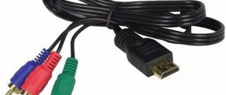
HDMI to VGA adapter with YPbPr
This is a universal adapter, model HD1132
, with two outputs. The converter converts the digital signal received from HDMI into analog. Image transmission is carried out via VGA or YPbPr.
The VGA connector is male, which is connected to the end device, for example, a monitor or TV. YPbPr – tulip with three outputs. Resembles RCA, but the wires are colored green, red and blue, which corresponds to the RGB color model.
The converter has a short length of 5-6 cm, which requires an HDMI cable to increase. The length is also increased with a VGA cable. If the VGA connector of the monitor is busy or missing, but there is an input for YPbPr, connect an adapter to the latter. It comes included and is a wire with a VGA input and a YPbPr output.
The sound is output via HDMI to the jack built into the converter. The kit includes an adapter for audio: jack to optical connector. This allows the audio to be converted to meet modern audio standards.
The converter supports Full HD resolution with a screen refresh rate of 60 Hz. Has built-in HDCP, protecting the signal from interference. Powered by a powerful source via HDMI or built-in USB. Also ideal for connecting projectors and game consoles.
HDMI to VGA adapter with YPbPr + S/PDIF + RCA
This is a converter, model HD1181
, powered from the electrical network. Contains four outputs. Supports one of two simultaneously connected sources - via VGA and YPbPr. To switch between the latter, there is a key on the main panel of the device.
Sound is transmitted via optical cable or RCA. The S/PDIF output allows you to connect the device to a single-input RCA interface and transmit video and audio signals.
Acceptable resolution is 1920×1080 VGA or 1080p YPbPr. The permissible screen refresh rate is 50 or 60 Hz, respectively. The converter is used as an adapter or analog signal splitter.
HDMI connectors (mini, micro) and their pinouts
- Type "A" - 19 pins, specification 1.0
- Type "B" - 29 pins, specification 1.0
- Type "C" - 19 pins (mini), specification 1.3
- Type "D" - 19 contacts (micro), specification 1.4
- Type "E" - 19 pins, specification 1.4
Pinout HDMI Type A (19pin)
Pinout HDMI Type B (29pin)
Pinout HDMI Type C mini (19pin)
Pinout HDMI Type D micro (19pin)
| Contact | Signal Description | |||
| HDMI Type A (standard) | HDMI Type B | HDMI Type C (mini) | HDMI Type D (micro) | |
| 1 | 1 | 2 | 3 | TMDS Data2+ (Video signal, pair 2) |
| 2 | 2 | 1 | 4 | TMDS Data2 Shield |
| 3 | 3 | 3 | 5 | TMDS Data2- (Video signal, pair 2) |
| 4 | 4 | 5 | 6 | TMDS Data1+ (Video signal, pair 1) |
| 5 | 5 | 4 | 7 | TMDS Data1 Shield |
| 6 | 6 | 6 | 8 | TMDS Data1- (Video signal, pair 1) |
| 7 | 7 | 8 | 9 | TMDS Data0+ (Video signal, pair 0) |
| 8 | 8 | 7 | 10 | TMDS Data0 Shield (Video Signal Shield) |
| 9 | 9 | 9 | 11 | TMDS Data0- (Video signal, pair 0) |
| 10 | 10 | 11 | 12 | TMDS Clock+ (Video Clock) |
| 11 | 11 | 10 | 13 | TMDS Clock Shield |
| 12 | 12 | 12 | 14 | TMDS Clock- (Video clock frequency) |
| — | 13 | — | — | TMDS Data5+ (Video signal, pair 5) |
| — | 14 | — | — | TMDS Data5 Shield (Video Signal Shield) |
| — | 15 | — | — | TMDS Data5- (Video signal, pair 5) |
| — | 16 | — | — | TMDS Data4+ (Video signal, pair 4) |
| — | 17 | — | — | TMDS Data4 Shield (Video Signal Shield) |
| — | 18 | — | — | TMDS Data4- (Video signal, pair 4) |
| — | 19 | — | — | TMDS Data3+ (Video signal, pair 3) |
| — | 20 | — | — | TMDS Data3 Shield (Video Signal Shield) |
| — | 21 | — | — | TMDS Data3-(Video signal, pair 3) |
| 13 | 22 | 14 | 15 | CEC (Signal) |
| 14 | 23 | 17 | 2 | Reserved (HDMI 1.0-1.3c) HEC Data- (HDMI 1.4+ with Ethernet) |
| — | 24 | — | — | Reserved (Reserved in the cable, but not connected) |
| 15 | 25 | 15 | 17 | SCL (I2C Serial Clock for DDC) |
| 16 | 26 | 16 | 18 | SDA (I2C Serial Data for DDC) |
| 17 | 27 | 13 | 16 | DDC/CEC/HEC Ground |
| 18 | 28 | 18 | 19 | +5V Power (max 50 mA) |
| 19 | 29 | 19 | 1 | Hot Plug Detect (All versions) HEC Data+ (HDMI 1.4+ with Ethernet) |
What equipment can be connected
Using a VGA HDMI cable, you can connect various devices that transmit graphic or audio information to each other.
Video card for monitor
This is the most common use of a converter. It is used to assemble a personal computer. A VGA HDMI cable allows you to connect the corresponding outputs of two devices while maintaining resolution and image quality. The location of the connectors does not matter: the converter converts the digital signal to analog, but the direction does not matter. In this way, not only one, but also several monitors are connected.
The device allows you to connect an HDMI monitor to a VGA video card, although such a connection is rarely necessary. A male-to-male connection is used.
Video card for TV
This connection method is used to use a computer and view information from it on a TV. The principle of operation is similar to a regular monitor, but sound output is carried out in two ways. The first is by simply connecting a jack 3.5 to a computer. The second is by using a special converter called a tulip. It has 4 outputs: one is connected to the video card, and the other three are connected to the TV. Among the last three: two are RCA, and the last one, which transmits the image, can be VGA, DVI-D, RCA. In this case, only HDMI is connected to the computer, transmitting sound, while the latter will be emitted from the TV.
Read also: Connecting a hammer drill button with reverse
The adapter allows you to connect the VGA of your computer to the HDMI of your TV. This is used when connecting a video card with an outdated connector to a modern TV. Power is supplied via USB.
Laptop to TV
The connection is used like the previous one - to view a computer image on a large screen. The HDMI VGA adapter allows you to connect not only a PC, but also a laptop with a working monitor to the TV.
Laptop to external screen
The connection is used if the built-in screen is broken and cannot be replaced. The monitor is also connected to a laptop as an alternative to the main one, even if it is working, or as an additional device. Dual-screen computers are used in some professions that require viewing programs at the same time.
Projector to computer
The need to use a projector occurs in various institutions. But often the connectors on the devices do not match. In this case, the use of a converter is required, since most projectors display an analog image.
Studio equipment for computer
Studio equipment includes cameras used to capture images. Converters are used when recording to a device connected to a computer by wire. This is found in cinema and professional photography studios. The image immediately goes into the processing program, where special effects specialists and editors process the footage, and photographers apply various filters.
Medical equipment for computer
The adapter is used to connect various professional devices to a computer. This could be an ultrasound or x-ray device, a tomograph, etc. Even in medicine, image transmitting devices and computers differ in connector.
Pinout of HDMI connector to RCA tulip
Typically, an HDMI to RCA adapter is used when it is necessary to reproduce or transmit data in video and audio format. This connecting cable has a built-in special chip that acts as a converter of the HDMI digital signal into composite video or audio. This signal is then sent through the tulip connector to the TV screen.
To convert a purely digital HDMI signal into an analogue one (S-Video, component or composite), you need not just an adapter, but a whole device consisting of a digital signal receiver, several DACs, a television signal conditioner, and a bunch of other little details. It's too complicated to just call it an adapter.
The design of the adapter is made in the form of a miniature hardware module with a wire. At one end there is an HDMI connector, and at the other there are three multi-colored tulip connectors.
Recommended adapters
Converter male HDMI - female VGA HD 1161 - signal converter. It acts as a full-fledged converter, powered by HDMI. Manufacturer: VConn. The cost of the device is 600 rubles. Suitable for PC, not suitable for PlayStation 3, Xbox 360 and projectors. For game consoles and projectors, it is necessary to use a full-fledged converter with mains power.
To connect, you need to screw VGA to the corresponding output, and HDMI to the signal source. The cable length is 20 cm, which is inconvenient in some installations. To extend the wire, you will need a 2 HDMI connector, both connectors are female.
The details of the HDMI VGA adapter are shown in the following table.
One dark winter evening I was given the task of making a TV for the kitchen from a monitor. Fortunately, the monitor was already there. The problem was successfully solved, details under the cut.
First of all, I went to the market and bought a DVB-T tuner with an HDMI output (both DVI and VGA are not available) and speakers. The tuner cost 15 bucks, the speakers 4 or 5 - accordingly, there was no point in waiting from China. But the adapters were only HDMI-DVI, which gave some hope. But alas, none of the existing monitors wanted to work with such an adapter. There are no adapters for VGA for sale, and what is available at online flea markets somehow significantly exceeds the cost in China, and you still need to look for a seller who will agree to send it by mail, which, by the way, makes the project even more expensive. 10-15 bucks for an adapter - a sorter.
This adapter took so long that the thought of ordering a new one came to my mind several times. The track was sold, but it went somewhere to Turkey and froze there. Well, to hell with it - imagine my surprise today when the notification arrived, and upon receiving the parcel I found this damn adapter there.
The megadevice itself is a box measuring 45x45x15mm, with a female VGA connector on one end and a 3.5mm audio jack and a 20cm cable with an HDMI-male connector on the other. NO external power supply.
The micro-USB connector is not soldered on the board and apparently there is some kind of small power socket. Soldering and assembly for four. The kit includes a male-to-male 3.5mm jack cable.
Well, it's time to move on to assembling the unit. hmm... the tuner only has one USB socket, and that's on the front. And the speakers are powered by a USB connector... Accordingly, either the speakers or a flash drive, for example. Well, or another power supply unit, which is somehow too much. This means that you will have to embed a USB connector to power the speakers on the rear panel.
Let's parse and cut:
We solder two M3 nuts to the USB socket - do we need to secure it somehow?
We look for + and - on the board, which are connected to the corresponding contacts of the native connector, and solder a new connector to these contacts:
Result:
The adapter successfully picked up the 1080p resolution, like all the others available to the tuner and monitor (though on those with the letter i, the picture shakes quite a bit, but here I don’t know who is to blame, and why, if there are other options). The picture is surprisingly good, the sound is clear and loud. If it weren’t for the speed of delivery, I could recommend it, but otherwise I’m not sure, and by this time the goods had already disappeared from the seller.
In general, I am quite pleased with the rework, but if it comes to that, you need to take a monitor with built-in speakers for this purpose, this is a much better solution IMHO. And ideally - also with HDMI - then not only will there be only one connecting cable, but also, as far as I understand, the monitor can turn on and off when the tuner is turned on and off. However, this depends on the monitor, apparently. But even in this form, the whole system cost me about 25 bucks (we assume that the monitor is in stock). But there are undoubtedly some inconveniences in the form of a bunch of wires and the need to turn the monitor on and off separately from the tuner. But this can also be considered a plus - the speakers now work independently of the monitor