Our generation lives in the era of a scientific and technological revolution, but since we are “inside the process,” we do not notice the rapid change of generations of technical devices around us. If previously household appliances could serve for decades, now in two or three years they become hopelessly outdated - new ideas, new technologies and materials appear that allow these ideas to be implemented.
Since the creation of the first spark transmitters, radio-electronic equipment has been analog. However, after World War II, when the bipolar and field-effect transistor were invented and the first integrated circuits were developed, digital technology began to gain its place in the sun. From a circuit design point of view, digital equipment is more complex than analog equipment, but its functionality is much wider, and some of them are fundamentally unattainable with analog signal processing. Despite this, in the field of modern television technologies, analog video signals are used very widely and are not going to become a thing of the past.
The problem with the digital representation of a video signal is that the width of its spectrum is many times greater than the width of the spectrum of the same video signal, but in analog form. Modern digital television systems, which are gradually being switched to all over the world, are not capable of working with an uncompressed signal. It has to be encoded using the MPEG algorithm, which is known to be a lossy algorithm. So it turns out that despite the development and improvement of digital technologies, it is easier and cheaper to use analog video formats to transmit video signals over long distances: the signal spectrum width is quite acceptable, the equipment fleet is extensive, and the technologies have been developed to perfection.
Digital interfaces DVI and its development HDMI are, in general, interfaces of the near future, but they are intended to solve other problems.
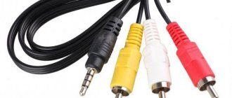
The analog video signal used in modern television systems can be composite or component.
Composite CV
(composite video) is the simplest type of analog video signal in which information about brightness, color and synchronization is transmitted in a mixed form. In the early stages of the development of video technology, it was the composite signal that was transmitted over a coaxial cable that connected VCRs or video players to televisions.
A more advanced version of the composite signal is the S‑Video
. This type of analog video signal provides separate transmission of the luminance (Y) signal and two combined chrominance (C) signals via independent cables, which is why this signal is also called YC. Because luma and chrominance signals are transmitted separately, S-Video occupies significantly more bandwidth than composite. Compared to a composite video signal, S-Video provides a noticeable gain in image clarity and stability, and to a lesser extent in color rendition. S-Video is widely used in semi-professional equipment, broadcast studios, and also when recording on 8 mm film in the Hi-8 standard from Sony.
These interfaces are not suitable for high-definition television and computer video because they do not provide the required image resolution.
Description VGA
| VGA plug | VGA socket |
VGA (DE-15) - 15-pin subminiature analog connector for connecting monitors using the VGA video interface standard.
VGA was developed in 1987 and is intended for cathode ray tube monitors. Some DVD players and many plasma and LCD TVs are also equipped with this interface.
VGA transmits the signal line by line, and a change in voltage means a change in brightness (the signal voltage is 0.7-1 V), for a CRT it means a change in the intensity of the beam of the electron guns of the kinescope (and, accordingly, the brightness of the light spot on the screen).
By the 2010s, VGA was outdated and was being actively replaced by digital interfaces DVI, HDMI and DisplayPort. The largest electronics manufacturers Intel and AMD announced a complete abandonment of VGA support in 2015. Most monitors that no longer have a VGA connector are connected to a video adapter with a combined DVI-I output using an adapter, since some of the DVI connector lines are VGA interfaces for compatibility purposes (with the exception of the DVI-D format, which does not have analog lines).
The VGA connector has found its niche in industrial automation and control. This connector is most popular for connecting various types of devices using the RS-485 standard and creating ModBus protocol architectures.
Today, almost all manufacturers of video cards and monitors have abandoned this connector, which, in case of incompatibility and the presence of only digital video outputs (only HDMI, Display Port, DVI-D is present) and an analog video interface, requires the purchase of a converter adapter to connect the old monitor to the new video card .
Component video signals
To achieve maximum image quality and create video effects in professional equipment, the video signal is divided into several channels. For example, in an RGB system, the video signal is divided into red, blue and green components, as well as a sync signal. This signal is also called the RGBS signal; it is most widespread in Europe.
Depending on the method of transmitting synchronization signals, the RGB signal has several varieties. If the synchronization pulses are transmitted in the green channel, then the signal is called RGsB, and if the synchronization signal is transmitted in all color channels, then RsGsBs.
To connect the RGBS signal, use cables with four BNC connectors or a SCART connector.
RGBS video cable with BNC connectors.
SCART connector
Table 1. SCART connector pin assignments
| Contact | Description |
| 1. | Audio output, right |
| 2. | Audio input, right |
| 3. | Audio output, left + mono |
| 4. | Audio Ground |
| 5. | Ground for RGB Blue |
| 6. | Audio input, left + mono |
| 7. | RGB Blue input |
| 8. | Input, switching TV mode, depending on the type of TV - Audio/RGB/16:9, sometimes turning on AUX (old TVs) |
| 9. | Ground for RGB Green |
| 10. | Data 2: Clockpulse Out, only in older VCRs |
| 11. | RGB Green input |
| 12. | Data 1 Data output |
| 13. | Ground for RGB Red |
| 14. | Ground for Data, remote control, only in older VCRs |
| 15. | RGB Red input or Channel C input |
| 16. | Blanking Signal input, TV mode switching (composite/RGB), “fast” signal (new TVs) |
| 17. | The land of composite video |
| 18 | Ground Blanking Signal (for pins 8 or 16) |
| 19. | Composite video output |
| 20. | Composite video input or Y (luminance) channel |
| 21. | Protective screen (housing) |
The YUV system, which has become widespread in the United States, uses a different set of components: mixed luminance and synchronization signals, as well as red and blue color difference signals. Each component system requires a different type of equipment, and each has its own advantages and disadvantages. To connect devices of different video formats, special interface blocks are required. The connectors at the ends of the cables are usually RCA or BNC.
YUV component signal
RGBHV format component signal
The way a video signal is formed is as follows: the image is decomposed into signals of three primary colors: red (Red - R), green (Green - G) and blue (Blue - B) - hence the name “RGB”, to which horizontal and vertical synchronization signals are added ( HV), and then turns into an RGB signal with sync pulses in the green channel (RGsB), which is further converted into: a component (color difference) signal YUV, where Y=0.299R+0.5876G+0.114V; U=R–Y; V= B-Y, which is then converted into S-Video and composite video. The composite video signal is converted into an RF signal that combines audio and video signals. It is then modulated by a carrier frequency and turned into a broadcast television signal.
At the receiving side, the radio frequency signal is converted as a result of demodulation into a composite video signal, from which, in turn, as a result of a series of transformations, RGB and HV components are obtained.
The YPbPr component signal is converted to RGB + HV, bypassing many video circuits. Separating the Pb and Pr chrominance signals into separate channels significantly improves the phase accuracy of the color subcarrier, and color tone adjustment is not required.
High definition television signals (HDTV) 720p and 1080i are always transmitted in component format; HDTV in composite or s-video formats does not exist.
When the DVD format was born, it was decided that when digitizing material for recording on DVD, it was the component signal that would be converted into digital form and then processed using the MPEG-2 video data compression algorithm. The RGB signal output from a DVD player is derived from the YUV component signal.
It is important to note the difference between the ratio of color components in RGB and the component signal of the YUV format (YPbPr). In the RGB color space, the relative content (weight) of each color component is the same, whereas in YPbPr it takes into account the spectral sensitivity of the human eye.
| Ratio of components in RGB color space | Component ratio in YPbPr color space |
Limitations on the transmission distance of component types of video signals from signal sources to receivers are summarized in Table 2 (for comparison, some digital interfaces are also shown).
| Signal type | Bandwidth, MHz | Cable type | Distance, m |
| UXGA (component) HDTV/1080i (component) | 170 70 | Coaxial 75 Ohm | 5 5-30 |
| Component UXGA (amplified) | 170 | Coaxial 75 Ohm | 50-70 |
| Standard (digital SDI) HDTV (digital SDI) | 270 1300 | Coaxial 75 Ohm | 50-300 50-80 |
| DVI-D | 1500 | twisted pair | 5 |
| DVI-D (amplified) | 1500 | twisted pair | 10 |
| IEEE 1394 (Firewire) | 400(800) | twisted pair | 10 |
VGA pinout
| plug (wire side) | socket (wire side) |
1. Red channel – 75 Ohm, 0.7V. 2. Green channel - 75 Ohm, 0.7V. 3. Blue channel -75 Ohm, 0.7V. 4. Second identification bit. 5. Common wire. 6. “Ground” of the red channel. 7. “Earth” of the green channel. 8. “Earth” of the blue channel. 9. Key. 10. "Ground" synchronization. 11. Zero identification bit. 12. Single identification bit, or DDC data. 13. Composite or line synchronization. 14. Frame synchronization. 15. DDC clock, or third identification bit.
general information
This output of analog signals to the monitor is familiar to almost every personal computer user. The VGA connector is designed to connect any modern TV or monitor. The interface in question can be found both on the latest equipment and on quite old ones. In modern laptops, in order to minimize the space occupied by the connector on the device body, manufacturers most often do not use screw fastenings of the cable to the connector, so the user must be extremely careful when moving the laptop.
Non-standard modes (X-modes)
By reprogramming the VGA, it was possible to achieve higher resolutions compared to standard interface modes. The most common “abnormal” modes were:
- 320×200, 256 colors, 4 pages. Outwardly no different from the 13h mode (320×200, 256 colors), the mode has four video pages, which allows for double and even triple buffering.
- 320×240, 256 colors, 2 pages. In this mode there are fewer pages, but the pixels are square.
- 360×480, 256 colors, 1 page. Maximum resolution of 256 colors possible for implementation within VGA.
All of the above modes use a planar video memory organization similar to that used in 16-color modes. However, it uses 2 bits from each plane to generate color, rather than one at a time. This organization of video memory allows you to use the entire video memory of the card, and not just the 0 plane at 64K, to form a 256-color picture. And this, in turn, makes it possible to use high resolutions/many pages. To work with this memory, the same sequencer is used as in the 16-color modes.
However, due to the characteristics of the video memory controller, the process of copying data to video memory is four times faster than in 13h mode.
The term " Mode X" was coined by Michael Abrash in 1991. It was used to designate a non-standard 320x240 mode with 256 colors. This mode was discovered by studying proprietary IBM documentation by various programmers independently of each other. The term became famous thanks to articles by Michael Abrash in the magazine “Dr. Dobb's Journal."
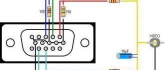
Is it possible to make a VGA to HDMI adapter with your own hands + functional diagram
Despite the fact that prices for VGA to HDMI adapters are at an affordable level, not everyone is ready to give their “hard earned” money for this device. If the user has a sufficient level of knowledge in electronics, he can try to assemble the equipment himself. In fact, this is not so simple, so it is better for an unprepared person not to resort to this method. Especially for the most technically savvy readers of the Tehno.guru resource, our editors post here the functional diagram of the VGAßàHDMI adapter. Take advantage and improve your skills!
Thanks to this visualization, “techies” will be able to show all their skills
Bonus! The VGA to HDMI adapter or cable does not work on the monitor. What to do
It happens that when you connect a device to a monitor, no action occurs. Why does this happen? In 95% of cases the following reasons occur:
- You bought a low-quality product without following our advice. There is nothing you can do to help here, you just need to buy a better product, and leave the old one... as a souvenir of your mistake.
- Your monitor or motherboard has failed. In this situation, either repairs from qualified specialists or complete replacement of equipment helps.
The remaining 5% of cases include various minor failures of the adapters. Here is an example of such a situation and adequate troubleshooting:
Standard modes:
- 40x25 characters , 16 colors, resolution 360x400 pixels.
- 80x25 characters , 16 colors, resolution 720x400 pixels.
- 80x25 characters , monochrome, resolution 720x400 pixels.
By using fonts smaller than the standard 8x16 , you can achieve more lines in text mode. For example, if you enable the 8x14 , there will be 28 lines available. And if 8x8, then the number of lines will increase to 50 (as in EGA 80x43 ).
For each cell with a symbol in text mode, you can specify an attribute that specifies the display option for this symbol. There are two separate sets of attributes: for color modes and for monochrome. Color mode attributes allow you to select one of 16 character colors, one of 8 background colors, and enable or disable flicker, which coincides with the capabilities of CGA. The attributes of monochrome modes are the same as those available from MDA (in particular, they allow you to activate increased character brightness, underline, flicker, invert, and some combinations thereof).