Examples of ATS schemes
Let's start considering the schemes with one point, which is better to immediately identify. The difference between the ATS circuits “automatic + starter” and “automatic with electric drive” is the efficiency of the latter option for currents starting from 200 amperes, less space in the cabinet and greater resistance to overloads that occur during switching on. But depending on the schemes, this decision must be made individually. And so in any scheme, instead of an automatic machine with a starter, you can install an automatic machine with an electric drive.
ATS circuit for two inputs on a contactor
So we have two inputs here. Each input has an input machine or switch. There is also a third machine, which is responsible for the consumer load. And the main role in this theater is played by the contactor, which I designated K1. It has a winding and two contacts - normally closed and normally open. The principle of operation of the circuit is as follows: when the voltage fails, the power from winding K1 is lost and the contacts are switched.
The disadvantages of this scheme are that when there are walruses of light, power will be thrown back and forth. This, of course, will not allow you to be left without light, but the contactor itself, namely its contacts, will wear out significantly, even to the point of replacement. Since all the current will pass through them. Therefore, the currents with such a circuit should be small. And such modes are not good for load.
ATS circuit with magnetic starters
Let the starters in this diagram be designated K1 and K2. Although starters are usually designated as CM, I even call them “kaems”. This circuit can be single-phase or three-phase. I drew it single-phase, it’s easier and faster. This means that the principle of operation is as follows: we turn on “input No. 1” and immediately contact K1 opens on the zero side of winding K2. Then we turn on “Input No. 2”, winding K2 is already open and therefore contact K2 in the zero circuit K1 will not open and will not cause K1 to turn off. Further, if the power is lost at input No. 1, then contact K1 in the zero circuit K2 becomes closed again, power reaches the winding on both sides and starter K2 is triggered. Our K1 starter is disabled and therefore the power comes from the second input. If voltage appears again at input No. 1, then to return you will need to manually turn off the second input and turn on the first. It's not very convenient.
In this scheme, it turns out that the working input will be the one that is turned on first. It also doesn’t inspire much confidence, but it’ll do for the first time. To switch the power back to the first input, you can install a voltage relay. This means that its winding will be connected in parallel to the “coilK1 - contactK2” chain, and its contact will be closed in series in the “coilK2 - contactK1” chain. Don’t forget to monitor the operating current of the load and contactors of the starters.
AVR circuit for three inputs
In most cases, the AVR circuit for three inputs consists of two inputs plus a diesel generator. The essence of its operation: when the power disappears at the first input, the second one turns on, and when two inputs disappear at once, the diesel generator turns on. When electricity reappears at one of the two inputs, power is transferred from the diesel generator to the newly turned on input. Implementing these schemes yourself is to your detriment, since there are ready-made solutions - configured brains, where you just need to connect the wires and set the settings. Something similar was discussed in the article about BAVRs.
If you want to get acquainted with the factory versions of ATS circuits in more detail, search engines provide many pdf files from various manufacturers.
Latest articles
Most popular
We automate the start of a gas generator
Well =) The task has arrived.
TZ: There is a gas generator on the Honda GX390 engine, with a starter, but without an automatic start board. You need to do autostart with integration into the AVR system. Without investing a lot of money.
Well damn, said and done. Ready-made solution = replacement of the gas unit, yeah. PLC controllers are in short supply due to their high cost and in general you can only buy them in 2022 (Those who work on a budget will understand).
After a short meeting, we decide to manufacture non-standard equipment, but with reservations:
Firstly. Financial costs are kept to a minimum.
Secondly. Installation if possible DIP, because The service personnel are not particularly used to SMD.
Third. We make two copies to allow for timely replacement.
Fourthly. Almost anyone can figure out the code.
So what? Naturally, the first thing that came to mind was Arduino.
OK. I ordered a pair of Arduino pro mini, found a couple of boxes from control panel controllers, relays, harness, and step-down DC-DC stubs. In short, the cost is 300 rubles.
I created a signet in Sprint Layout.
It turned out tolerably, I entered the input of the generator start signal through an optocoupler, set a watchdog timer on NE555, and threw in a DS18B20 thermometer in order not to close the damper on a hot engine.
Three relays control power to the ignition coil, choke solenoid and starter armature.
Then he etched it with a laser iron. A little cheesy in places, but the Rose alloy solved this problem.
I built it into a breadboard, assembling a circuit of LEDs and buttons to simulate a generator start signal.
The algorithm is simple: Upon receiving the SG signal, we ask the jampers for the starter holding time, then we give power to the ignition system, If the engine is cold, then we attract the carburetor flap solenoid (If it’s hot, then it’s not necessary), We turn on the starter, after N seconds the starter is extinguished, the flap is released, We maintain the ignition until the ignition signal disappears.
Well, this is what happened. Tomorrow we will draw a diagram of the entire ATS, select a shield, and starting in the New Year we will put it all together. For one thing, we’ll collect a second copy.
What is an AVR and its purpose.
In addition, the ATS controller checks for the absence of a short circuit, otherwise the supply of energy to this section is unacceptable. BUAVR has increased resistance to overvoltage.
From a technical point of view, a three-phase voltage monitoring relay consists of a measuring and power part. When the voltage disappears at the first input, contactor-1 disappears and the contactor turns on. In this part, we will analyze the circuit for a three-phase electrical network, made on two contactors, where a phase control relay of a three-phase voltage control relay is used as a control element.
But there may be more power sources. The consumer remains with the light.
It consists of two single-pole circuit breakers, one contactor and one double-pole circuit breaker. In this case, you can turn the machine on or off using special buttons. Thus, in the absence of voltage, the system will switch the consumer from the main to the backup input, however, when voltage appears on the line, reverse switching is possible only manually - by turning off the power with the AB2 circuit breaker or stopping the generator. Connection diagram for ATS (380 Volts)
https://youtube.com/watch?v=YCkQXV0x8w4
Related links
- Rules for the technical operation of consumer electrical installations / Regulatory document dated February 9, 2007 at 02:14
- Electrician's Bible / Regulatory document January 14, 2014 at 12:32 pm
- Handbook on electrical networks 0.4-35 kV and 110-1150 kV. Volume 10 / Regulatory document from March 2, 2009 at 18:12
- Kabyshev A.V., Tarasov E.V. Low-voltage circuit breakers / Regulatory document dated October 1, 2022 at 09:22
- Rules for the installation of overhead power lines with voltage up to 1 kV with self-supporting insulated wires / Regulatory document dated April 30, 2008 at 15:00
- Knyazevsky B.A. Trunkovsky L.E. Installation and operation of industrial electrical installations / Regulatory document dated October 17, 2019 at 12:36
- Mankov V.D. Zagranichny S.F. Protective grounding and grounding of electrical installations / Regulatory document dated March 27, 2022 at 09:05
Purpose of AVR
Long interruptions in power supply lead not only to discomfort and inconvenience. They can cause serious property damage and pose a threat to the life, health and safety of people.
Consumers of the 1st category can be simultaneously connected to two power sources. If one of them is turned off, electricity will still flow to the consumer. However, this scheme has significant drawbacks. When short circuit currents appear, their parameters will be significantly higher compared to separate power supply.
Electricity losses in the supply transformer will significantly exceed the norm. A more complex relay protection system will be required. Sometimes the simultaneous operation of two power supplies becomes impossible due to the equipment and relay protection that were installed previously.
Description of the device
Automatic transfer of reserve is a system that is needed to provide power supply loads with a reserve charge. It is carried out in two versions. It can be one-sided or two-sided. In the first there is a division into a working and a reserve section, but in the second there is no such thing. In the first case, you can switch to normal mode or emergency mode; in the second case, these modes are not necessary.
Safe operation of electrical equipment as one of the purposes of the device
The main purpose of the module is to make the power supply system more reliable. This device quickly connects loads to the backup input type when power outages occur. To ensure automatic switching, the system monitors voltage and current at all times. This is its purpose.
Explanation of the abbreviation AVR
The abbreviation is deciphered very simply. ATS is an automatic transfer of reserve. Sometimes switching is used instead of the word input, but this is incorrect, because by input is meant generator start-up as a backup source.
How does the abbreviation stand for?
Classification
Depending on the design of the AVR unit, the equipment is classified according to the number of sections, type of network, voltage class, power and response time.
Note! ATS is often available with one, two and three outputs to ensure high network reliability. Also available in single-phase, two-phase and three-phase
According to the voltage class, it handles up to 1000 volts.
AVR cabinet for three inputs
Primary requirements
When purchasing and installing on a network, users are required to have the ATS:
- ensured the supply of energy in the event of an unforeseen interruption in line operation;
- restored electrical power as quickly as possible;
- necessarily acted once, that is, there should not be several modes of operation at once;
- turned on the main power before the backup electrical power was supplied.
In addition, it must monitor the health of the equipment control circuit.
Fast restoration of electrical power is the main requirement for the system
A simple ATS circuit for 2 inputs on magnetic starters
Scheme on magnetic starters
The schematic diagram of connections on starting devices is used for single-phase circuits; this option is not suitable for three-phase circuits. The electrical circuit is simple because it uses a minimum of elements, but this does not reduce its efficiency. To activate, SA1 and SA2 are turned on in turn. If there is voltage used to power the load, at the first input the second output will remain free, that is, backup.
If the voltage disappears at the first contact, the power will automatically switch to the second input. If a load appears on the first one again, then nothing will happen on the second input until it disappears. Returning a de-energized device to its original, off state will trigger the open contact element. The latter is installed in the coil power circuit.
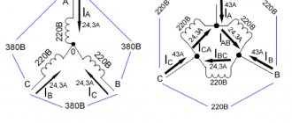
Despite its simplicity, this electrical circuit is reliable, although it does not use a starter locking mechanism, but its implementation will not harm. The power supply to other outputs can be switched by briefly disconnecting the power line of the first or second machine. The voltage supplying the main and additional inputs is 380 V. But the current parameter of the coils on the starters is 220 volts.
Automation without controller
there is a serious drawback
Automation in this version cannot turn off the network at low and high voltage, as well as control the parameters of the power plant, record important events and errors, on the basis of which diagnostics will be carried out in the future.
In practice, the operation of the ATS unit will be reduced to the following: one or two LEDs will act as informing elements, and in accordance with the instructions, one blink will correspond to one situation, double blink to another situation, and if there is a pause between the blinks, to a third situation. If you entrust the installation of this device to a specialist, then do not be surprised if he refuses to work with this travesty or demands that you pay more for the work.
Simple automatic transfer systems
It all works very simply. ATS circuit on two contactors: We hope that this short article will help you assemble and launch an automatic transfer circuit on a contactor, and the power supply to your home or small business will become uninterrupted. Recoverable AVRs. We install a circuit breaker with a rating of at least A2; if we cannot purchase a switch, we install a circuit breaker with a rating higher than A2
The closing contacts of contactors must be designed for the full load current; for breaking contacts, this does not matter, block contacts can be used. Both automatic machines QS1 and QS2 must be turned on, in which case the KM coil will receive power and be drawn in, and accordingly its closing contact in the main input circuit is also closed and the breaking contact in the backup input circuit is open. Such uncontrolled switching is completely unacceptable in continuous-cycle industries or in medical institutions in hospital operating rooms, for example, as well as at other important facilities
In the future we will improve the circuit, adding time delays and various blockings. If the voltage disappears, relay K1 is de-energized, K1. The switch is selected with three positions, where the middle one completely cuts off the electricity. External inputs for emergency shutdown of inputs. Such a relay performs the function of constantly monitoring the voltage parameters of the main network. Since both inputs are in operation, there is no need to monitor the readiness of the backup line to accept the load.
How does automatic backup power input work?
In accordance with individual conditions, the ATS circuit is additionally equipped with a starting unit, which controls the start of an autonomous power source, be it batteries with an inverter or a liquid fuel generator. Monitoring the state of the contactor contacts. When the voltage in the main line disappears, the KM 1 coil is de-energized, and power through the closed contact KM1 begins to flow to the KM 2 winding, through the contactors of which the backup input is connected to the load. Currently, the industry produces a wide range of ready-made AVR units
For such important facilities as hospitals, defense industry facilities, and for many others, accidents at power plants or power supply networks promise great trouble, it is for this reason that much attention has always been and is paid to the design and construction of backup power supply systems
When the current parameters in the main circuit are restored, the contacts of the main circuit contactor are closed while the contacts of the reserve contactor are simultaneously opened. This method is less expensive than a generator, but is not capable of delivering current for a long time for powerful household appliances. Currently, the industry produces a wide range of ready-made AVR units.
The purpose of the AVR is to increase the reliability of power supply to consumers. Moreover, only one electric motor is used, and the inputs are switched by rotating it back and forth. The simplest three-phase ATS or how to connect the MAVR-3 control module
About grounding
Before you do anything with electricity, you need to make sure there is a good grounding in your home.
You won’t be able to simply take and connect a regular household gasoline/diesel/gas generator to the electrical network at home. Precautions must be taken. The first is that your generator must be well grounded. Then you have a good chance of not getting an electric shock when the static from your favorite sweater penetrates the insulation of the generator winding. In general, you should not touch a running generator unnecessarily. It is worth remembering that the network is not always 220V. Switching on lines, lightning discharges in the distance, and static discharges produce such interference that short pulses of several kilovolts are not uncommon in the network. They combat this by installing arresters and surge protection devices at the entrance to the house, but this is a very rare practice in the Russian Federation. So let the spark go into the ground, and not through you - make good grounding throughout the house. Without this, you simply cannot do anything further!
ATS circuits for 3 inputs
In such an electrical circuit, the load is supplied from two power sources of the main network, they are marked - Input 1 and 2. The system is also powered from an autonomous device, it is marked as Input 3. If there is voltage at two inputs, then the power is supplied through switches with a drive. QS is a switch that turns off part of the voltage. If the voltage parameter at both inputs is normal, ATS devices transmit a command to activate elements 4QS-7QS.
From the first input, power is supplied through the 1QS switch, as well as the 1QF switch device. The load is then transferred through the contact elements of switches 4QS and 6QS. The load from the second input is supplied in the same way, only through a 2QS switch and a 2QF switch device. Then it flows through the contact elements of the 5QS and 7QS devices. The second output is powered by the voltage supplied from the first input. The first ATS device sends a command to the 5QS switch, causing the device to be activated.
Power passes through the following circuit:
- first entrance;
- switch 1QS;
- 1QF device;
- reversible element 5QS;
- exit 1.
If there is no voltage at the first and second inputs, then the command to start the generator device will be given after a certain time interval. When normal voltage appears at the third input, then after a while the second ATS is activated. As a result of this, all loads on energy consumers will be sent from the third input. Switches 6QS and 7QS are triggered. The third input will power the electrical network until the first and second inputs receive normal load.
Three input circuit
The main advantage of the three-input generator connection scheme is the use of blocking between the inputs.
Notes
- Automatic switching on of reserve // Benzar V.K. Dictionary-reference book on electrical engineering, industrial electronics and automation - Mn.: Vysh. school, 1985
- Automatic switching on of reserve // Encyclopedia of modern technology. Automation of production and industrial electronics. Volume 1 (A - I) - M.: Soviet Encyclopedia, 1962
- ↑ MA BERKOVICH, AH KOMAROV, V. A. SEMENOV Fundamentals of automation of power systems. —M.: Energoizdat, 1981. —432 p.
- ↑ GOST 30011.6.1-2012 Low-voltage distribution and control equipment. Part 6. Multifunctional equipment. Section 1. Automatic switching equipment
- Kadykov Y. Power supply systems for data centers using diesel dynamic UPS // NEWS of Electrical Engineering N 4(112), 2018
- Rules for the construction of electrical installations (PUE). Chapter 1.2 Power supply and electrical networks (Seventh Edition) clause 1.2.19
- GOST IEC 62310-1-2018 Static switching systems (STS). Part 1. General requirements and safety requirements
- Bushuev V.M. Power supply of communication devices - M.: Radio and communication, 1986. P. 122
- Gurevich Yu.E., Kabikov K.V. Features of power supply focused on uninterrupted operation of an industrial consumer - M.: Eleks-KM, 2005.
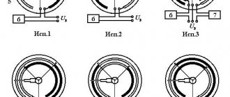
Addition to the article. Switch.
I provide a photo of the TDM MP-63 switch, with which you can manually switch between street and generator. The diagram is at the beginning of the article, only there is a single-pole switch that breaks the phase.
The switch in the photo switches both phase and zero:
Switch for switching the voltage source. It is in the middle position.
Attention! 63A on the body is not a thermal current, and the switch does not “knock out” like a regular machine! This is the maximum operating current. Switch for switching voltage source
Zero and phase outputs
Switch for switching the voltage source. Zero and phase outputs
Switch for switching the voltage source. Inputs of zero and phase of the city and generator
Why I strongly recommend using a two-pole switch and switching not only phase, but also zero - I have already written in more detail in this article.
Quick connection
Starting a gasoline generator when the lights are turned off should not cause much difficulty; there is a simple way with a regular connection to an outlet.
It is advisable that the socket be installed on the meter after the main input machine with a separate three-key switch. A cable with two plugs is used to supply energy. The main machine is turned off. This is done so that when the power supply from the main network is restored, the generator does not fail.
You need to check with a dipstick whether the oil level is normal, make sure there is fuel, turn the lever on the air filter and the gasoline supply valve to the on position. Start the starter and return the air filter lever to the reverse position, turn on the power to the outlet using the three-key switch.
This method is suitable for rare power outages. In case of frequent interruptions, a system is assembled, thanks to which the generator automatically starts when there is a power outage.
Operating principle of AVR
In normal mode, consumers are powered with a voltage of 380V from Input 1 or Input 2 through a common power contactor KM3, which is turned on after a certain time delay using a time relay KT1, this is done so that power is supplied when a stable operating mode occurs.
The presence of voltage at each input is controlled by voltage control relays KV1 and KV2. Switch SA1 is used to select priority input. If there is voltage on both inputs, the input whose priority is selected will be connected first (position “1” - the first input, position “0” - both inputs are disabled, position “2” - the second input).
Fig. 2 – Electrical circuit diagram of ATS with DGS on contactors
Operating principle of ATS with main inputs (Input 1 and Input 2)
For example, when the voltage disappears at Input 1, the voltage control relay KV1 is triggered and opens with its contacts the power circuit of the contactor KM1. If there is voltage at Input 2, the contacts of the KV2 relay are closed and if the KM1 contactor is in the off state, then the KM2 contactor will operate, while the KM3 contactor is in the on state and voltage is supplied to consumers through the closed power contacts of the KM1 and KM3 contactors.
The ATS is performed similarly for Input 2.
Operating principle of AVR with diesel generator set
If the voltage fails at the main inputs: Input 1 and Input 2, the generator control circuit is closed and the power circuit of the KM3 power contactor is opened. After the generator starts and the voltage control relay KV3 closes its output contact, time counting begins using a time relay with a turn-on delay KT2, which is necessary to stabilize the output parameters of the generator. At the end of the countdown, the power supply circuit of the KM4 contactor is closed and the generator power is connected.
When voltage is restored at any of the main inputs. For example, the voltage at Input 1 has been restored, in this case the voltage control relay KV1 is activated and its contacts close the power circuit of the contactor KM1. In this case, the output contacts of the contactor KM1 are closed and power is supplied to the time relay with a delay to turn on KT1.
After the end of the time countdown, the time relay KT1 closes the power circuit of the intermediate relay KL3, which in turn closes the power circuit of the coil of the contactor KM3 and opens the power circuit of the contactor KM4, after the contactor KM4 is turned off, KM3 will operate and through the closed power contacts of the contactors KM1 and KM3 voltage is supplied to consumers from the main Input 1.
Programmable relay EKF PRO-Relay
The main control of the operating logic is carried out by the EKF PRO-Relay programmable relay. This allows for more flexible implementation of the main functions of the control system.
In this scheme, a programmable relay controls the position of circuit breakers, ensures on-off switching of inputs, with its help time delays for operation of switches are set and changed, and diagnostic functions are performed.
In addition, if necessary, you can change the operation algorithm of the ATS circuit without extra costs and display the necessary information about the operation of the ATS to the upper level via Modbus, although this requires an additional interface module.
PRO-Design is used as software for PRO-Relay. The program can be downloaded for free from the official EKF website.
Also, to download the program you will need an ILR-ULINK cable, which will need to be purchased separately.
How to choose automation for a generator?
Automation for the generator is presented in 2 versions:
Box with contactors. If we are talking about industrial-type power plants equipped with an automatic panel, then it is not necessary to use a full-fledged shield for them. The fact is that the electric generator already has everything it needs: a controller; circuit breakers, etc. For this reason, power plants of this type are usually equipped with a box with contactors and an emergency shutdown button. There is no great need to dwell on this type in detail.
The only thing you should pay attention to when choosing is that the contactors purchased should not be made in China, and the device itself should be equipped with an emergency shutdown button for the electrical installation. Full AVR shield. They are equipped with portable equipment with a manual panel
It is with this that a large number of cases of consumer fraud are most often associated. Despite the fact that such products do not meet the requirements that must be met for such devices, they still ask for a lot of money.