The predecessors of the 16k20 lathe, produced by Soviet machine builders, were a number of screw-cutting lathes equipped with a gear gearbox. These metal-cutting machines bore names from DIP-200 to DIP-500. The abbreviation of the names spoke of the desire of the leadership, supporting the slogan of the 1st Five-Year Plan to catch up and overtake the leaders of capitalism.
The number following the letter part of the name corresponded to the height of the centers of the machine relative to the bed in mm. Machines with such names were produced from 32 to 37 of the last century. The change of names occurred as a result of the development and approval of the “Unified System of Symbols for Machine Tools” (USUS). According to the adopted document, the founder of the generation changed the name of DIP-200 to 1D62. However, the outdated name is still used as a general name for lathes with center heights of about 200 mm.
Purpose of the machine
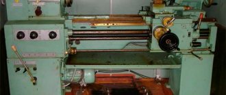
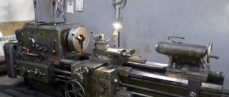
In the early 70s, Soviet Mash, after several modifications of the DIP models, launched the production of turning screw-cutting 16k20. Which in 1972 received a gold medal at the international fair in Leipzig.
Intended for a variety of turning operations, it made it possible to turn various simple and complex surfaces in the chuck, on the faceplate and in centers. And besides, boring, facing, cutting, and cutting all kinds of threads. Its design was so successful that in the USSR it was long considered the best equipment of its type. Screw-cutting machines differ from other representatives of the turning group in their greater versatility.
Therefore, their use is more rational in small-scale or piece production.
Instructions for the initial start-up of the 16K20 machine
During the initial start-up of the 16K20 machine, it is necessary to check the reliability of grounding and the quality of installation of electrical equipment by external inspection. After inspection, disconnect the power wires of all electric motors at the terminal sets in the control cabinet and connect the machine to the workshop network using the input circuit breaker. Check the operation of all locking devices
- Using manual controls, check the precise operation of magnetic starters and relays.
- Once smooth operation of all electrical devices located in the control cabinet is achieved, connect the previously disconnected wires to the terminal sets.
- By alternately turning on the electric motors of the main drive and quickly moving the caliper, check the correct direction of their rotation.
- After making sure that the electric motors rotate correctly, you can begin testing the machine in operation.
Factory markings and designations
In accordance with the ESUOS, the designation of a machine or its index consists of several numbers and letters. The first character is the group number. Turning equipment is assigned No. 1. The second indicates the variety or type of device in the group, for example, 6 corresponds to universal turning and screw-cutting equipment. Next is a number characterizing the most important dimensional parameter. For lathes it is the height of the centers above the base plane.
The letter located between the first and second digits of the index indicates that the model was obtained by improving its predecessor. The placement of the letter at the end of the designation indicates that this model is the result of a modification of the base one. The letter located in the middle is a sign that this is a basic model and serves as the name of the generation. Thus, the index 16k20 has the basic model of a new generation “K” screw-cutting lathe with a center height of 200 mm.
Precision designation
According to operating tolerances, turning equipment is usually divided into the following categories:
- N – normal accuracy;
- P – increased;
- B – high;
- A – especially high.
- C – especially accurate (master).
Repair of screw-cutting lathe 16K20
Below are links to three albums dedicated to the repair of a 16K20 screw-cutting lathe . This documentation was developed by the State Design and Technological Institute for Modernization and Automation, Repair of Metal-Cutting Machine Tools and Maintenance of Metalworking Equipment with Software Control - GPKTI STANCOSERVICE.
Content
- General description of the machine
- Purpose and brief technical characteristics
- Controls
- Specification of main components
- Basic parameters of gears, worms, screws, nuts, racks
- Kinematic diagram
- Specification of rolling bearings
- Machine lubrication
- Lubrication map
- Description of the electrical circuit
- Electrical circuit diagram
- Machine electrical equipment specification
- Drawings of machine components
- Bed 16K20.010.001; 16K20.011.001; 16K20.012.001; 16K20.016.001
- Spindle head 16K20.020.001
- Tailstock 16B20.030.001; 16B20P.030.001
- Four-position tool holder 16K20.041.001
- Carriage and support 16K20.040.001 and 16K20.050.001
- Apron 16B20P.061.000
- Feed box 16B20P.070.000
- Gearbox 16K20.080.001
Download for free “Repair of screw-cutting lathe 16K20. Album 1. General description" in normal quality (70 pages) can be found at the link below:
Contents “Repair of screw-cutting lathe 16K20. Album 2. Technological process of major repairs"
- Route of a 16K20 screw-cutting lathe during a major overhaul
- List of equipment used during major repairs of the machine
- Route technological process of disassembling the machine into units
- Recommendations for defect detection and restoration of parts
- Route technological processes for parts repair
- Requirements for the quality of machine assembly
- Route technological process for assembling machine components
- Route technological process of assembly and debugging of the machine
- Testing the machine after a major overhaul
- Protocol for checking the machine for rigidity and accuracy according to GOST 18097-72
- Noise Level Standards and Test Methods
- Applications
Download for free “Repair of screw-cutting lathe 16K20. Album 2. Technological process of major repairs" in good quality (100 pages) can be found at the link below:
Contents “Repair of screw-cutting lathe 16K20. Album 3. Replaceable parts"
- Temporary norms for the consumption of replaceable parts when repairing a 16K20 machine
- Working drawings of replacement parts
Download for free “Repair of screw-cutting lathe 16K20. Album 3. Replaceable parts" in good quality (196 pages) can be found at the link below:
Specifications
- Accuracy group – N.
- Center height (mm) – 215.
- Ø standard cartridge – 200 or 250 mm.
- The speed range of rotation of the spindle shaft in the direct direction (rpm) is 12.5–1.6*103. Adjustment discrete number of gears 24.
Moreover, both in the forward and reverse directions there are 2 gears with a frequency of 500 and 630 rpm. Therefore, some sources talk about 22 forward and 11 reverse transmissions.
- The speed range of rotation of the spindle shaft in the reverse direction (rpm) is 19–1.9*103. Adjustment discrete number of gears 12.
- Feed range (mm/rev): along the axis – 0.05–2.8; across 0.025–1.4.
- The pitch range of metric threads is 0.5–112 mm.
- The range of modular thread pitches is 0.5–112 modules.
- The range of inch thread pitches is 56–0.5 threads/inch.
- The range of pitch thread pitches is 56–0.5 pitches.
Limit parameters
- The maximum permissible diameter of a “disc” workpiece turned over the bed is 400 mm.
- The maximum diameter of the “shaft” type workpiece turned over the caliper is 220 mm.
- Limit length of the workpiece to be turned (mm) – 710, 1000, 1400, 2000.
- Limit length of turning (mm) – 645.935, 1335, 1935.
- The Ø of the “rod” type workpiece is no more than 50 mm.
- The weight of the workpiece fixed for processing in centers (no more) is 460, 650, 900, 1300 kg.
- The weight of the blank fixed for processing in the chuck (no more) is 200 kg.
- The force developed by the feed unit at the stop (no more) is 800 kgf along the axis, 460 kgf across it.
- The force developed by the feed unit on the cutter (no more) is 600 kgf along the axis, 360 kgf across it.
List of lubricants recommended for lubrication of the 16K20 machine
| I-20A GOST 20799-75 | I-30A GOST 20799—75 | CIATIM-203 GOST 8773-73 |
| Viscosity at 50°C 17—23 cSt | Viscosity at 50°C 27—33 cSt | Effective viscosity at -30°C — no more than 1000 Pz |
| Flash point (in open crucible) — not lower than 165°С | Flash point (in open crucible) — not lower than 180°С | Corrosion test - withstands |
| Pour point - 30°C | Pour point - 15°C | Content of free alkalis in terms of 0.1% |
| Acid number - no more than 0.14 mg KOH/1 g oil | Acid number - no more than 0.2 mg KOH/1 g oil | |
| Ash content — no more than 0.007% Content of mechanical impurities - absent | Ash content - no more than 0.007% Content of mechanical impurities - absent | Free organic acid content - none Water content - no more than 2.5% |
| Content of water-soluble acids and alkalis - none | Content of water-soluble acids and alkalis - none | The content of mechanical impurities is no more than 0.25% |
| Water content - none | Water content - none | |
| Replacement with IGP-18 TU38-1-273—69 is allowed | Replacement with IGP-30 TU38-1-273—69 is allowed |
In the absence of lubricants specified in the list, it is permissible to use only those oils whose main characteristics correspond to those given.
Electrical circuit diagram
There are 3 operating voltages in electrical equipment:
- Motor power supply –380V.
- Automatic - 110V.
- Workplace lighting – 24V.
List of machine electrical components:
- R – Load indicator E38022 (ammeter ~20A).
- F1 – Current protection circuit breaker AE-20-43-12.
- F2 – Automatic AE-20-33-10.
- F3, F4 – E2782—6/380 – fuse link.
- F5 – TRN-40 – electrothermal protection.
- F6, F7 – TRN-10 – electrothermal protection.
- N1 – safety light-signal device UPS-3.
- N2 – NKSO1X100/P00-09 – electric lamp with S24-25 lamp.
- N3 – KM24-90 – switching lamp.
- K1 – PAE-312 – remote magnetic starter.
- K2 – PME-012 – remote starter.
- KZ – RVP72-3121-00U4 – time delay relay (Limit of operation of the main motion electric motor without load).
- K4 – RPK-1-111 – engine starter.
- M1 – Main motion electric motor 4A132 M4, rated power 11 kW.
- M2 – 4А71В4 – electric motor (accelerated displacement of the caliper).
- M3 – Electric pump PA-22 (emulsion supply).
- M4 – 4A80A4UZ – asynchronous electric motor.
- S1 – VPK-4240 – limit switch (Distribution device door).
- S2 – PE-041 – rotary control switch (unlocking S1).
- S3 and S4 – PKE-622-2 – push-button control unit.
- S5 – MP-1203 – microswitch.
- S6 – VPK-2111 – push-type limit switch.
- S7 – PE-011 – rotary control switch.
- S8 – VPK-2010 push-type limit switch.
- T – TBSZ-0.16 – step-down transformer.
Diagram of lathe controls
Locking devices for electrical equipment of machine 16K20
The electrical circuit includes a lock that turns off the input circuit breaker when the control cabinet door is opened.
When the input circuit breaker is turned on, opening the cabinet door triggers the limit switch, which disconnects the electrical equipment of the machine from the network.
When the housing of the replacement gears is opened, a microswitch is activated, turning off the main drive motor.
The limit switch is mounted in the control cabinet, the microswitch is on the feed box housing.
For inspection and adjustment of electrical equipment under voltage (with the cabinet door open), the circuit provides a release switch installed in the control cabinet. This switch should only be used by qualified electricians.
Exploitation
A slight increase in the gaps between mating parts, leading to a decrease in processing accuracy, is eliminated by adjustment. Significant wear requires repair or replacement of parts. To reduce wear and prevent mechanical breakdowns during operation, it is necessary to follow the rules of equipment care.
Main movement
Since the cutting process occurs due to the rotational energy of the blank, it is usually called the main movement of the turning group equipment. The main movement drive consists of a single-speed three-phase asynchronous electric motor equipped with a manual gearbox.
Feed movement
The translational movement of the tool, ensuring contact of the cutter with the surface of the workpiece at the desired point, is called the feed movement. Its drive switches depending on the task being performed and can be manual or mechanical due to the power of the main drive.
Feeds and main movement are the main movements of the turning group equipment.
Longitudinal and transverse feed of the caliper
To move the support along and across the axis of rotation of the blank, longitudinal and transverse slides are used, respectively. Each of them is equipped with its own guides and screw drive. Transverse feed allows you to change the depth of cut and, in combination with longitudinal feed, form the required surface of the part.
Multi-start thread cutting
The selection of replacement gears is done in the same way as for cutting a single-start thread. With the difference that to determine the thread progress, its pitch must be multiplied by the number of starts. If the drive of the upper slide of the caliper is not too worn, division into approaches can be done by setting the latter parallel to the axis of rotation of the part. After cutting the groove in the first pass, the cutter, removed from the metal, is returned to its beginning. Then the cutter is retracted to a distance equal to the thread pitch from the first start. After which they begin to cut the second one.
Processing of shaped surfaces
The production of products with complex surfaces is possible in several ways:
- Using conventional cutters using alternating longitudinal and transverse manual feed. The method has low accuracy and productivity. Requires well-developed execution technique.
- Special shaped cutters. The method is highly productive, but requires non-standard cutters.
- With ordinary cutters using copiers or circular feed devices. The method is highly productive, but requires manufacturing or equipment.
Installing and removing the machine chuck 16K20:
- When installing and removing the chuck, protect the guides and bed with wooden boards placed under the chuck. Hold the chuck while you loosen the 3 cam locks by rotating ¼ turn counterclockwise. Align the A marks with each other. Carefully remove the cartridge.
- Before starting installation, you should make sure that there are no nicks on the mating surfaces and thoroughly wipe them with a lint-free cloth. Install the chuck onto the front end of the spindle. Clamp the cam lock of the clamping eccentric by rotating clockwise. The clamping eccentric mark A (Fig. 5) must be located between the 2 marks B (Fig. 5). The accuracy of the chuck fit on the spindle is checked by an indicator using a control band located on the outer cylindrical surface of the chuck body. Radial runout should not exceed 0.02 mm. Fig.5 Installing and removing the machine chuck 16K20.
- The fixed steady rest serves primarily to support long workpieces and ensures their reliable processing without vibrations; it is mounted on the frame using a fastening strip. *
- Install the steady rest crackers so that there is no gap between them and the workpiece and they do not pinch it. During processing of the part, it is necessary to lubricate the crackers well.
- The movable steady rest is installed on the longitudinal slide of the support and thus repeats the movement of the turning cutter. It prevents elastic deformation of long and thin workpieces under the pressure of a turning tool. When machining a workpiece, it is necessary to install the crackers in the same way as on a stationary rest.
Prevention and repair
Daily care activities
Before starting work:
- Inspection of the machine.
- Lubricate the lead screw and shaft.
- Controlling the amount of oil.
- Switching on with checking nodes without load.
During operation:
- Switch feeds and gears only after the moving units have finally stopped.
- When working with cast iron or abrasive materials, cover the guides with thick cloth.
After the end of working hours: turn off the power supply, remove the shavings, wipe with a rag soaked in kerosene, and lubricate the open guides with oil.
Malfunctions and their elimination
| Symptoms | Cause | Correction method |
| Ovality of the part or hole being bored. | Blank runout in the cartridge. | Boring of jaws. |
| Quill play or weak fastening of the thrust headstock. | Adjusting or repairing the quill. | |
| Hole axis offset. | Misalignment of spindle shaft and tailstock. | Adjustment. Or repair with adjustment. |
| Significant cone of cylindrical parts. | Mismatch between the centers of the spindle shaft and the thrust head. | Adjustment. |
| Worn caliper or bed guides | Adjustment or repair. | |
| Dimensional instability during trimming. | Axial play of the spindle shaft. | Replacing rotation bearings. |
A slight increase in caliper clearances can be eliminated by adjusting the wedges in the transverse or upper slide guides, and the adjustment screws in the rear guide of the longitudinal slide. Then, moving the slide to the maximum distance, make sure that it moves smoothly. Leaks in the screw drive of the cross slide are eliminated by adjusting the screws located behind the tool holder platform.
Description of the lubrication system of the 16K20 machine
The 16K20 machine uses an automatic centralized lubrication system for the spindle head and feed box.
The pump, driven from the main drive electric motor through a belt drive, sucks oil from the oil bath and delivers it through a strainer to the spindle bearings and oil distribution trays. About a minute after turning on the electric motor, the oil indicator disk on the spindle head begins to rotate. Its constant rotation indicates normal operation of the lubrication system.
During operation, it is necessary to monitor the rotation of the oil indicator disk on the spindle head of the 6K20 machine. When it stops, you must immediately turn off the machine and check the filter. Remove the filter mesh elements in the plastic frame. Rinse each element in kerosene until completely clean. Do not blow out the filter elements with compressed air, as this may damage the fine mesh. After cleaning, assemble and install the filter.
ATTENTION! Filters must be cleaned before and after each oil change. In a new machine, it is advisable to clean the strainer at least twice a week for the first two weeks, and then once a month.
Every day before starting work, you need to check the oil level in the tank using the indicator and, if necessary, add it through the hole in the filler filter. When changing the oil, the reservoir is drained through a plug. Before filling the tank with oil, it must be cleaned and rinsed with kerosene.
The apron mechanism is automatically lubricated by an individual plunger pump. Oil is poured into the housing through hole 5 (Fig. 3), closed with a plug, and drained through hole 6 (Fig. 3). The oil level is controlled by the oil indicator on the front side of the apron.
The frame guides are lubricated using a centralized lubrication system of the caliper apron (repeatedly, depending on the intensity of use).
The guides of the transverse carriage, the upper carriage, as well as their lead screws must be lubricated using an oil can.
The carriage guides and cross slides are lubricated at the beginning and middle of the shift until an oil film appears on the guides.
Every day at the end of the shift, you need to remove the cutting head from the 16K20 lathe, clean its working surfaces and lubricate the conical axis of the tool holder.
Replacement gears and the axis of the intermediate replacement gear 12 (Fig. 3) are lubricated manually with CIATIM-203 GOST 8773-73 grease.
The support bushings of the replacement gears are lubricated using an oil can.
The remaining points are lubricated manually using the oil can supplied with the machine.
ATTENTION! The first oil change should be made a month after putting the 16K20 machine into operation, the second - after three months, and then strictly following the instructions of the lubrication chart.