Equipment Specifications
The screw cutting machine has a wide range of technical features:
- The power of the electric motor ensures the functioning of the main drive and reaches 7.5 kW. And the drive itself, responsible for moving the caliper, has a power of 0.37 kW. The electric motor for the lubrication mechanism is 0.12 kW;
- the maximum length of the workpiece to be turned is 1.46 meters, and the maximum dimensions of the product fixed at the centers of the machine are 1.5 meters;
- Automatic transmission;
- thread cutting is carried out by the worker selecting a step, which he sets based on the type of workpiece;
- the maximum cross-section of the workpiece turned above the bed should not be more than 40 centimeters, and above the support - 21 centimeters;
- the number of revolutions of the spindle device in forward motion is from 25 to 2500 rpm, and in reverse motion – from 25 to 1250 rpm;
- in forward movement, the spindle device has 21 speed levels, and in reverse – 18;
- the machine is driven by a 2-speed electric motor together with a gearbox and a bulkhead that programs 12 speed levels of the spindle mechanism in any of the 2 ranges;
- transverse feeds vary from 0.025 to 1.4 mm, and longitudinal feeds - from 0.05 to 2.8 mm per rotation;
- The range of movement of the caliper along the screw is 75 centimeters (lengthwise) and 22 centimeters (crosswise). The maximum distance of its movement along the roller is 50 centimeters;
- Rolling bearings create rigid and high-precision support;
- the guides of the carriages and the rolling pairs of the screws have impulse lubrication;
- feed drive provides stepless feed adjustment;
- loading and unloading of parts is carried out manually.
These technical parameters enable the car to enjoy popularity even 50 years from the date of its release. The letters “K” and “P” in the name of the machine indicate that there is a copying mechanism and an increased degree of accuracy, respectively. The screw cutting machine is capable of operating from a mains voltage of 220, 380, 400, 415 and 440 V. It is characterized by a modern ergonomic structure and is easy to operate and control.
Dimensions and weight of the machine
The screw cutting machine is small in size and weight for a machine with similar functionality:
- width – 1110 millimeters;
- height – 1505 millimeters;
- length – 2270 millimeters;
- weight – 2 tons.
Purpose and scope
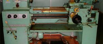
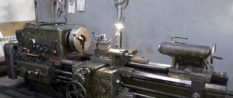
The 16b16kp machine is intended for performing various turning operations in centers, collets or in a 3 or 4-jaw chuck, for cutting various threads with a die or tap. Unlike most other brands, such a machine is intended for more thorough turning, and therefore is not recommended for roughing. It is usually installed in small repair shops. After processing on a lathe, the products are distinguished by excellent surface cleanliness.
Scheme of the machine 16B16KP. Screw-cutting lathe. Electrical principle
Below is a sketch of the electrical circuit diagram of the 16B16KP lathe
You can download a free electrical diagram of the 16B16KP screw-cutting lathe in good quality from the link above. It is contained in the Electrical Manual
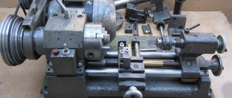
Structural components and mechanisms of the machine
The machine has a number of main components:
- Caliper.
- Gearbox.
- Transmission.
- Rear grandma.
- Main bed.
- Apron.
Mechanisms:
- protective parts. There is a mechanism to protect the worker and aggregate components from chips generated during the execution of work. This significantly increases the degree of safety and service life of the machine;
- A mechanism responsible for changing gears has been introduced into the screw cutting machine. This significantly increased the functional reliability of the screw cutting machine;
- electrical equipment. The main parts of the electrical system are 4 asynchronous electric motors of the screw cutting machine with different powers. Almost all elements are located in a special cabinet;
- The turning machine has longitudinal shut-off stops, a protective device against excessive loads, and a mechanism for blocking feeds in all directions.
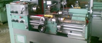
Screw-cutting lathe 16B16KP
The screw-cutting lathe 16B16KP is designed for performing a variety of turning operations, as well as for cutting metric, inch, modular and pitch threads. The 16B16KP machine differs from the 16B16P machine by the presence of an automatic feed box.
Due to the fact that the machine can be used in various industries for various operations, for processing various materials, maintenance of the machine should be carried out taking into account the specifics of their operation.
Gearbox
This 6-stage unit is installed in a separate housing and secured at the rear to the outer wall of the left transverse face. To tension the belt that goes from the box to the spindle device, it is capable of moving vertically using a screw. The device runs a 2-speed electric motor via a belt drive. Pulley 16, interconnected with hub 15, transmits rotational motion to shaft 14, which easily passes through sleeve shaft 20.
Shaft 14 is interconnected with coupling 25, when launched, the stroke from it passes to the shaft-sleeve 20 linked to it through half-coupling 24. This unit allows you to produce 6 speeds on pulley 13. The stroke is transferred to the headstock pulley by a belt drive. Connected to shaft 4 is coupling 3 with screw 12, which produces stable and efficient braking of the machine. All wheels 7-11, 18, 19, 22 are made from steels that have been subjected to heat treatment with further grinding, as well as alloying. The elements are lubricated by a pump using irrigation.
Headstock
The unit is started by a gearbox with a belt drive and an acceptance pulley 7 with a seal 4. The selection of axial play in the bearings is carried out by a spring 4. The unit acquires 12 rotational speeds from the acceptance pulley with a clutch 5; another 12 - through wheels 5, 8, 16, 15 with a bulkhead of 1:4, and 12 - through wheels 5, 8, 11, 10, 13, 14, 16, 15 with a bulkhead of 1:16. Starting the bulkhead groups, clutch 12 or turning off the spindle to divide into passes when cutting threads is done using a handle by translations through a lever mechanism, which is controlled by cams.
Strong fixation of the handle axis, which prevents rotation, is ensured by a spring-loaded ball located on the rear wall of the machine frame body in a glass. The rotation of the spindle device occurs with the help of 2 roller bearings 18 and 21. The clearance in the bearings is selected by springs 20. The transmissions are carried out by wheels 1, 2, 22, 23, 24 and the above wheels. The spindle, which has a flanged end and is made according to GOST, facilitates quick change and stable fastening of the faceplate. The device allows you to cut:
- thread with increased pitch of 4 and 16 times;
- right and left threads;
- multi-start threads when working with bulkheads 1:4 and 1:16 with a number of starts of 2, 3, 4, 5, 6, 10, 12, 15, 20, 30, and when working directly - with a number of starts of 2, 3, 4, 6, 12.
Tailstock
It is connected to the frame with a handle. Its position is controlled by a mandrel located along the marks or in the centers. The gap between the rear quill and the rotating axis of the spindle must be more than 0.1 millimeters. The flat end of screw 4 slides in the groove of disk 3. To unscrew screw 4 to dismantle disk 3, you need to align the counterbore with it. Control of the correct position of the body is carried out by the areas suppressed during assembly and exactly by the mandrel, which is clamped in the central parts of the machine. Pin 8 is clamped by handle 7.
Important! The maximum travel of the quill is 120 millimeters. Screw 9 moves from flywheel 2.
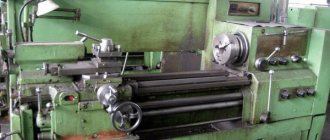
Machine bed
Mounted on 1 cabinet. This unit is represented by a cast iron box with transverse ribs in the shape of the letter “P” - equipped with 2 flat and 2 prism-shaped guides, which have undergone heat treatment and grinding. In the niche of the right end of the unit there is an electric motor for the rapid movements of the sled. A gearbox is mounted on the rear wall at the left end of the unit, at the right end there is a lubrication station, as well as a coolant tank and a cooling device pump; The main drive electric motor is located inside.
Kinematic diagram of a lathe model 16B16KP
Kinematic diagram of a lathe model 16B16kp
- A - AKS - automatic gearbox AKP 109-6.3 for machines 16B16K, 16B16KP, 16E16KP
- a - spindle head
- b - tool holder
- in — caliper
- g - tailstock
- d - apron
- e - carriage
- g - gearbox for machines 16B16, 16B16P, 16G16
* for spindle speed 16..1600 rpm
** for spindle speed 25..2500 rpm
Apron
The apron has 4 pairs of couplings, making it possible to produce direct and reverse movement of the caliper and slide. The movement of the slide and the lower part of the caliper is controlled by a handle, the direction of launch of which corresponds to the direction of their movement. Starting rapid movements of the caliper in 4 directions allows you to additionally press the IB button, which is located in the handle. At the same time, the electric high-speed motor is started, which sends movement to the drive shaft through a belt drive.
Lubrication of the assembly parts is done by a piston pump embedded in the cover. The unit is equipped with a blocker that prevents the joint start of the feed of the uterine nut and the caliper. It also contains a special protective device that protects against overload and is designed for the highest switching force (6000 ± 500)H. When working on the stops, the value can be lowered to the desired level by using nut 6, as well as by loosening spring 7.
Model features
The machine has a number of features:
- the gearbox of the device is characterized by a long service life, which is ensured through the use of a V-belt system;
- the apron of the machine equipment is equipped with a handle with which the spindle rotation speed is controlled;
- the machine support and longitudinal slide are capable of moving rapidly longitudinally and transversely;
- the headstock is equipped with two gearboxes with different gear ratios;
- the device is equipped with a specially designed tool holder, which allows the operator to quickly remove the working tool from it when cutting a part;
- the equipment has been assigned accuracy category “N”;
- the unit is capable of operating in several modes, which is ensured by the use of a thyristor-type electric drive;
- There is a handle on the apron of the machine that controls the movements of the longitudinal slide and caliper at an accelerated pace.
Machine apron
All operations performed on a screw-cutting lathe are characterized by precision and high cleanliness of the thread. This is due to the fact that all the basic parts on it are of high precision, the spindle supports are equipped with high precision bearings.
All machine elements are carefully balanced. The device is characterized by stepless adjustment of cutting speed in various ranges.
The device is marked “K”, which means it contains a copy mechanism. The marking “P” indicates the high accuracy of processing products with a machine of this type.
The turning-screw-cutting electrical unit has in its design:
- a device that blocks feeds in 2 directions;
- longitudinal switching stops;
- a system that protects the device from overloads.
Safety precautions
- Carry out work exclusively on screw-cutting machines for which you have access, and perform only the required work.
- Focus on work without being interrupted by unnecessary things and conversations; do not disturb other workers.
- Do not lean on a functioning lathe or allow others to do so.
- Do not give permission to your place to persons not related to the specific work. Do not trust the machine to another worker without the foreman’s approval.
- If you see another operator failing to comply with the rules, give him a warning about the obligation to comply with the provisions of the instructions.
- During repair work on the machine and starting mechanisms, it is necessary to hang a poster on it: “Do not start - repair.”
- It is prohibited to work on a lathe that is faulty and does not have the required guards, as well as to repair or remodel the machine yourself.
- Immediately inform the technician about any incident and go to the first aid station.
- To avoid accidents, contamination and chips getting into the devices of the screw-cutting machine, it is prohibited to blow air from a hose onto the surface being turned and the machine.
- It is forbidden to work on a lathe while wearing mittens and gloves, as well as with bandaged fingers without rubber fingertips.
- The dimensions and weight of the product being turned must meet the requirements of the lathe machine's technical passport.
- Firmly and rigidly fasten the workpiece being turned.
- If there is any interruption in the electrical power supply, immediately turn off the equipment.
- If there is voltage (feeling of current) on the metal parts of the screw-cutting machine, the electric motor operates in 2 phases (there is a hum), the ground wire is broken, stop the operation of the machine and immediately inform the foreman about the malfunction of the electrical equipment.
- Use a wooden grate and take proper care of it.
Machine 16B16KP. Screw-cutting lathe. Manual. Electrical equipment
This operating manual for electrical equipment “Screw-cutting lathe 16B16KP” contains information necessary both for the maintenance personnel of this machine and for the employee directly involved in working on this machine. This manual is an electronic version in PDF format of the original paper version. This documentation contains a manual (instructions) for operating the electrical equipment of a screw-cutting lathe model 16B16KP.
CONTENT
- General information
- Description of work
- Protection and blocking
- Initial launch
- Installation and operating instructions
- Recommended lubricants for rolling bearings of electric motors
- Safety instructions
- Applications. Electrical diagram of the machine
download the operating manual for the electrical equipment of the screw-cutting lathe 16B16K P in good quality from the link below.