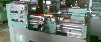
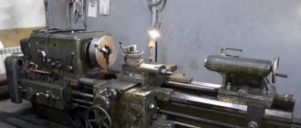
The 1A616 lathe has a long history: it began to be produced back in the mid-50s of the last century. The production of this machine, which many experts recognize even from the photo, was carried out by the Srednevolzhsky Machine Tool Plant. This model can still be found in many manufacturing plants today.
Screw-cutting lathe 1A616
Functionality of the machine 1A616
The functionality of this equipment is represented by the operations listed below:
- turning the surfaces of parts of arbitrary shape (including their facing);
- spot drilling;
- cutting grooves of various depths;
- deployment of standard holes;
- thread preparation using a cutter or tap;
- formation of mesh corrugations.
The presence of a large number of various functions turns turret lathes into universal mechanisms, the advantages of which include their low cost.
Description of the lathe
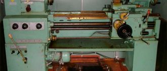
About 70 years have passed since the production of 1a616 lathes ceased, but they are still in use in small workshops. This indicates a multiple safety margin that the designers laid down at the time.
The main purpose is cutting workpieces made of various metals and alloys, as well as non-metallic materials. It is technologically possible to perform the following work:
- straight and conical turning of external and internal cylindrical surfaces;
- direct and conical boring of external and internal cylindrical surfaces;
- end trimming;
- cutting several types of threads;
- turning to caliber after retrofitting.
Basic equipment and technical characteristics of the equipment
The set of 1A616 machines includes samples of carbide cutters, which, if necessary, are used for cutting threads. In addition, it has a special set of high-speed cutting tools.
The machine has the following operating characteristics:
- The maximum length of workpieces to be processed is 71 cm.
- The range of turning performed on the machine is 66 cm.
- The maximum size of the installed blanks, fixed on top of the support, is 18 cm, and directly above the frame – 32 cm.
- The diameter of the working shaft for the spindle is 3.5 cm.
- The weight of the frame with attachments is 1.5 tons. The threaded end of the spindle shaft is of the “6K” type.
And finally, the dimensions of the machine body in the classic design are 2.1 x 1.22 x 1.2 meters.
Repair features
Lathe 1k62d
Almost all components of the 1A616 machine have features for disassembling and replacing elements. To avoid mistakes, work should be carried out by carefully studying the drawings contained in the equipment operating instructions. Also, a lot of information on carrying out individual repair operations can be found on special resources.
To carry out complex work, for example, replacing a dog clutch, you should strictly follow the instructions given in the documentation for the equipment. Here you will find all the data related to repairs, allowing you to adjust the bearing or configure the operation of an entire functional unit of the machine.
How to remove a cartridge
Some jobs are quite simple. In particular, removing the cartridge. It is of a cone type, fixed with four faceplate nuts on bolts. To remove this element of the assembly, just unscrew them. It is worth noting separately: in some modifications of the machine, a removable faceplate is not used; instead, a permanent chuck mounting is located on the spindle.
How to remove the faceplate
Removing the faceplate is difficult. It is screwed very tightly onto the gear shaft of the headstock, the mass of the part is quite large, so turning the connection manually is almost impossible. Disassembly experience without the use of special tools has shown the effectiveness of the following options, which require the use of gearbox gears.
- Move the chuck jaws apart and place a crowbar or a thinner piece of metal between them. Turn the spindle so that the lever is located in a position convenient for lowering with force, just above the head. Turn on the transmission gearbox to minimum speed and turn on the search. When starting to rotate, sharply pull the rod down. This operation is potentially dangerous, both due to injury and damage to the elements of the box.
- Clamp a hexagon with a spanner on it or a metal rod across the axis in the chuck. Rotate the spindle so that the end of the lever rests on the rear guide of the bed. Switch the gearbox to low speed, reverse rotation and turn on the drive. To avoid damaging the surface of the guide, it is recommended to place a board or other damper under the lever.
These methods are used for manual disassembly. However, to carry out repairs of this kind, it is recommended to invite professionals with special equipment.
Gearbox repair
If the tension of the drive belts is adjusted, the gearbox is repaired. To do this, the fastening screws are unscrewed, adjustments are made with the appropriate nut for each pulley, after which the fastening elements are installed in place.
Replacing V-belts for a twelve-speed gearbox is also not difficult. To do this, the lubrication system is partially dismantled. Remove the cap, flange, screws and supply tubes. Afterwards, screw the M12 screws into the holes provided for this until the axle box comes out of the headstock. Insert the belts onto the seam and perform all the operations performed in the reverse order.
Controls
The machine support is shifted along a screw axis in manual mode (its maximum value reaches 195 mm). For longitudinal movement, a special shaft is used, providing a maximum shift of 670 millimeters. The feed parameters are almost the same; they are selected by the operator within the range from 0.065 to 0.91 rpm.
It is possible to replace the gears included in the mechanism with their precision analogues, which guarantees ultra-precise threads. There is no need to change the feed speed to prepare standard cuts. When operating in precision mode, the lead screw is driven directly.
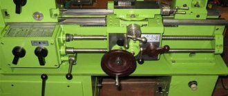
Machine speed box
The specificity of the 1A616 device allows switching the speed of the working shaft in a wide range of torques. For this purpose, it is equipped with a 12-speed gearbox, thanks to which the accuracy of thread cutting is noticeably increased.
This unit is installed in the internal cavity of the equipment and secured in such a way that it can be moved vertically.
Please note: The movable box mount allows you to adjust the tension of the transmission belts.
To control the gearbox, there are two handles on the frame that can be moved left and right. One of them is designed for 4 positions, and the other for three.
The working process
The feed movement during operation of metalworking machines 1A616 occurs from the spindle assembly to the support. The gearbox is able to ensure the operation of the equipment in 48 ranges, officially 22 of them are indicated, since some speeds are the same. To move the caliper longitudinally, a gear coupling is used, and in the transverse plane, a lead screw is used.
To cut threads with pitches of less than six millimeters, the caliper and spindle are directly connected to each other. Processing of large values is carried out using enumeration and an intermediate element of increasing the step. The main working movement of the equipment in question is the cutting moment performed by the spindle with the workpiece fixed in it. In addition, a pair of V-belt transmissions and a speed unit with 12 ranges are responsible for this process.
Kinematic diagram
The diagram under consideration allows us to imagine the location of all working units of the unit and their constituent mechanisms. To get acquainted with it, just look at the product passport.
Having studied the kinematics of the 1A616 machine (figure below), any machine operator can easily understand all the intricacies of its functioning. In addition, thanks to this knowledge, it is possible to use all the capabilities of the mechanism and, if necessary, improve your skills.
Brief history of the series
In 1957, SVSZ Samara (Srednevolzhsky Machine Tool Plant), founded in 1876, produced one of the best universal screw-cutting lathes, 1A616. It became a worthy replacement for its predecessor - the 1616 machine, which at that time was 8 years old (year of manufacture - 1949).
Today, the unit has been discontinued and replaced with more modern ones, but is nevertheless used in many enterprises, as well as by those who decide to engage in turning at home.
Purpose and scope of application of a metal screw-cutting lathe
The machine is designed for turning metal and metal workpieces. Processing is the cutting off of all excess layer by layer until it is given the shape, size and other required characteristics necessary for use.
For processing, the machine uses high-speed cutting tools such as R18, R6M5 and carbide (VK, TK, TTK) tools. The main types of work that can be carried out on a 1A616 series lathe:
- turning of external cylindrical and conical surfaces, ends;
- turning conical shaped surfaces;
- cutting metric, modular, inch and pitch threads with a cutter;
- cutting metric and inch threads with a tap and die;
- rolling mesh surface corrugations;
- cutting grooves and cutting;
- drilling, countersinking and reaming of holes.
Possibility of processing parts-bodies of rotation:
- shafts;
- rings;
- bushings;
- couplings;
- nuts;
- gear wheels.
Processing occurs by rotating the workpiece relative to the cutting tool
Main varieties and explanation of modifications
1A616 - the basic model of this series:
- 1 - lathe.
- A - improved.
- 6 - type of lathe (screw-cutting lathe).
- 16 - height of the centers of the machine (165 mm in this case).
1A616K:
- 1 - lathe.
- A - improved.
- 6 - type of lathe (screw-cutting lathe).
- 16 - height of the centers of the machine (165 mm in this case).
- K - the design of the machine has been modernized (here: an automatic gearbox has been added).
1A616S:
- 1 - lathe.
- A - improved.
- 6 - type of lathe (screw-cutting lathe).
- 16 - height of the centers of the machine (165 mm in this case).
- C - especially accurate.
1A616P:
- 1 - lathe;
- A - improved;
- 6 — type of lathe (screw-cutting lathe);
- 16 — height of the centers of the machine (165 mm in this case);
- n - increased accuracy.
1A616F3:
- 1 - lathe.
- A - improved.
- 6 - type of lathe (screw-cutting lathe).
- 16 - height of the centers of the machine (165 mm in this case).
- F3 - with numerical control (CNC).
Since different voltages can be used in different installation locations of the machine, the machines are divided into groups according to this criterion:
- 220V for working at home.
- 380V for mass production (plants, factories, etc.) is considered standard.
- 500V are made to order if required.
Specifications
The parameters given in the technical data sheet help determine whether this is the device you need for work. We invite you to consider the information provided.
Main parameters:
- Type - screw-cutting, universal.
- Series - 1A616.
- Accuracy - N (normal).
- The height of the centers is 165 mm.
- The distance between centers is 710 mm.
Spindle
Shaft for securing the workpiece in the chuck:
- Speed limits (forward and reverse rotations) 9–1800 rpm (if necessary, can be ordered with speeds from 11 to 2240 rpm).
- Hole diameter 35 mm.
- Internal Morse taper N5.
- The spindle is braked and the handles are locked.
Caliper and feed
Caliper (support) - a movable element, a unit for securing cutting tools or workpieces:
- Tool holder - 4 cutters.
- Cutter holder (largest dimensions 20x25).
- From the supporting surface to the center line 25 mm.
- From the center axis to the edge of the tool holder 170 mm.
- One front caliper with one cutting head.
Operating rules 1A616
To master the technique of operating a machine, you will need to understand such categories as its first start-up, as well as metal processing techniques, maintenance and care.
First launch of turning unit 1A616
Particular attention to putting the unit into operation is explained by the inability to foresee complications in its operation after delivery from the assembly line or long-term preservation. This procedure includes the following mandatory operations:
- reactivation of the machine;
- adding coolant and oil;
- visual inspection of structural elements and electrical wiring for their integrity.
Once the preparatory steps are completed, the machine can be put into operation.
Intake stroke and metal cutting
The machine spindle, driven by an electric motor, serves as a holder only in situations where it is necessary to cut threads no longer than 6 mm. If greater thread displacement is required, you will have to use the override and increased displacement function. For this purpose, it will be necessary to organize the simultaneous displacement of the drive shaft and the workpiece.
This can be achieved through separate motor drives mediated by the following transmission units:
- Support with 4 working positions.
- 12-speed gearbox.
- The previously discussed belt drive.
Everything taken together, acting simultaneously, ensures the achievement of the required synchronization of movements.
Electrical system of the machine
The electrical circuit of this model lathe includes the following elements:
- three fuses;
- switch installed at the input;
- lamp for illuminating the work area;
- voltage relay;
- switch for lighting lamp;
- contactors that control stopping the engine, turning on its operating and reverse operation;
- a switch that supplies voltage to the pump supplying coolant;
- a relay responsible for controlling the engine rotation speed;
- a relay responsible for controlling the engine stop contactor;
- a step-down transformer;
- machine control switch;
- load level indicator;
- selenium type rectifier.
Electrical circuit diagram of the 1A616 machine (click to enlarge)
The machine has two electric motors, each of which solves its own problem:
- three-phase electric motor PA22 with a power of 0.12 kW, with a rotation speed of 2800 rpm, operating on a voltage of 220/380 V, drives the pump that supplies coolant to the cutting zone;
- three-phase electric motor A02-41-4 with a power of 4 kW, with a rotation speed of 1430 rpm, operating on a voltage of 220/380 V, is used as the main drive of the machine.
To equip industrial enterprises, lathes operating on a voltage of 380 V are used, and for operation in a home workshop, models operating on an electrical network with a voltage of 220 V are optimal. In addition, upon special order, modifications of a lathe operating on an electrical network with a voltage of 220 V can be produced. voltage 500 V.
Kinematic diagram of the 1A616 machine (click to enlarge)
Power for the lighting lamp, which operates at a voltage of 36V, comes from a step-down transformer present in the electrical circuit of the machine. A special feature of this lathe is that its design does not have a motor responsible for the high speed of its support. Fast and at the same time smooth stopping of the engine, during which it does not heat up, is ensured through the use of direct current.
Maintenance and care
Maintenance and care of the machine require regular performance of the following mandatory operations:
- monitoring the operating oil level in the unit and topping it up if necessary;
- periodically wiping open metal parts from oil stains and rust deposits;
- carrying out preventive measures in accordance with approved maintenance schedules.
Only if these points are followed will it be possible to ensure uninterrupted operation of the equipment.
Principle of operation
The 1a616 lathe functions very simply. The master fixes the workpiece in the chuck or places it on centers. After this, the cutters are mounted in the tool holders, and the tool for creating holes is mounted in the quill. Now you can start processing any surface, be it a cone, end, cylinder or anything else. The configuration of the workpiece can be anything - the machine will cope with the task in any case.
The drive pulley is installed between the spindle supports. In turn, the master can quickly replace belts without removing the spindle. This is quite convenient and contributes to increased productivity.
An important feature of the 1a616 model is the presence of a separate format cutting drive. The design also includes a DC stator connected to the winding. This allows for quick braking if necessary.
Safety precautions when working with the machine
Compliance with safety precautions when working with the 1A616 unit comes down to fulfilling the following requirements:
- While the machine is operating, it is not allowed to touch the handles located on the gearbox and tailstock.
- When processing parts, it is necessary to use a screen (protective) mesh.
- When working with centered products with clamps, it is necessary to use a special chuck equipped with a protective rim.
And finally, according to the operating instructions, the machine doors must be tightly closed during the processing of workpieces.
Providing feed and cutting motion
The feed movement that the lathe support makes is communicated to it from the spindle assembly. In fact, the feed box of a machine of this model can provide 48 speeds, but due to the fact that some of these speeds coincide, only 22 are indicated in the device passport. In order to impart longitudinal movement to the support, it is necessary to use a gear coupling, and for the transverse feed of this unit The lead screw of the unit responds.
Feedbox 1A616 (click to enlarge)
In the event that it is necessary to cut a thread on the workpiece whose pitch does not exceed 6 mm, the support is connected directly to the machine spindle. If it is necessary to cut a thread with a large pitch, then to connect the support and the spindle, the search is turned on, and an intermediate step increasing the pitch is used.
The main movement in this lathe, as in devices of other models, is the cutting movement performed by the spindle and the metal workpiece fixed in it. From this movement, as mentioned above, the machine support is also activated, which can move in the longitudinal and transverse directions. The main elements of the drive responsible for the cutting movement are:
- two V-belt drives;
- 12-speed gearbox.
Gearbox 1A616
The gearbox of a lathe consists of three shafts installed in units with bearings, three moving blocks, each of which consists of two gears, and a single moving gear. By meshing gears with different parameters, the machine spindle is given different rotation speeds. Rotation from the gearbox is transmitted to the hollow shaft, and then, through a series of gears, to the machine spindle. In the event that the spindle needs to be given high rotation speeds, it is directly connected to the hollow shaft, for which a special cam clutch is used.
To control a lathe, which, according to even novice experts, is not very difficult, it is necessary to perform a number of manual operations. These include:
- turning the tool holder and installing it in the required position;
- movement of the tailstock, which houses the machine quill;
- installing the caliper in the required position.
Apron 1A616 (click to enlarge)
Intake stroke and metal cutting
The cutter holder receives feed movements from the main shaft of the device, as a result of which the tooth moves in a straight line. Based on the technical data sheet of the unit 1A616, the feed box is capable of providing 48 speeds. But in reality there are only 24 of them, since the speeds are the same. A clutch with fine teeth performs the function of launching feeds towards the axis, the lead screw is responsible for the perpendicular inlet.
Read also: How to use polyurethane foam without a gun video
The electric spindle of the 1A616 machine serves as a tool holder in situations where you need to cut small threads up to 6 mm. Increased shear and overhaul are used only when there is a need to cut at a larger stroke. To do this, you should point the wheel block to the right until the hollow shaft gear grabs the left circumference of the unit block. The cut represents the same movement of the drive shaft and the workpiece. Such rotation directs the cutter holder in an axial, and additionally perpendicular course, relative to the motor shaft. Movement is achieved due to the separate drive of the device, which consists of:
- caliper with 4 positions;
- 12-speed gearbox;
- 2 V-belt drives.