Weight of the machineThe cost of a lathe 1M65 (analogous to model 165) with a RMC of 3000 mm after overhaul is 2,120,000 rubles. . Warranty 6-12 months. Usually the equipment is in stock. In case of absence, the period of repair work is 45 days.
The rigidity of the structure and powerful drives make it possible to process large and medium-diameter workpieces made of metals of varying hardness using tools made of tool steel and hard alloys.
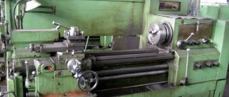
Design features of the model 165 lathe
- Precision processing, which is obtained due to the rigidity, vibration resistance and temperature stability of the structure;
- maintaining the original accuracy throughout the entire service life due to two prismatic guides of the frame, as well as due to the high reliability of the remaining components of the machine;
- reduction of time for thread processing due to the difference in the frequency of forward and reverse rotation of the spindle (the frequency of reverse rotation is 1.3 times higher);
- long cones are sharpened by simultaneous feed of the cutting slide and longitudinal feed of the machine support with their corresponding rotation;
- sufficient rigidity of the kinematic chain of the feed box;
- there are two electromagnetic clutches for remote gear shifting;
- gear power wheels of the kinematic chain are made of alloy steel and are subjected to hardening and grinding during production;
- Complete safety of work is guaranteed by fencing the chuck and cutting area and appropriate interlocks.
The 165 series screw-cutting lathe has been discontinued and is not currently produced by the manufacturer.
So you can only buy a metal machine 165 used on specialized sites and message boards for the sale of used (used) equipment, such as FROM HANDS TO HANDS, YULA, AVITO and others.
We offer to buy a 165 lathe after a major overhaul or a new analogue with similar characteristics.
Technical characteristics of the machine 165
Technical characteristics of the machine 165 are the main indicator of the suitability of the machine for performing certain jobs on the machine. For screw-cutting lathes, the main characteristics are:
- The largest diameter of the workpiece
- Distance between centers
- Maximum length of the processed product
- Spindle revolutions per minute
Below is a table with the technical characteristics of the screw-cutting lathe 165. More detailed technical characteristics of the machine can be found in the passport of the machine 165 located below.
Attention! The technical specifications given in the above table are for reference only. Machines produced by different manufacturers and in different years may have characteristics that differ from those given in the table.
Machine passport 165
This operating manual ( Machine Passport 165 ) contains information necessary both for the maintenance personnel of this machine and for the employee directly involved in working on this machine. This manual is an electronic version in PDF format of the original paper version.
CONTENT
Purpose and scope of the machine
Unpacking and Transport
Machine foundation, installation, installation
Technical data sheet of the machine
- Basic data
- Caliper
- Tailstock
- Additional data
- Drive unit
- Friction couplings
- Specification of the main groups of the machine
- Control Specification
- Specification of gears, worms, worms, screws and nuts
- Main movement mechanism
- Feed mechanism
- Replaceable gears
- Feed mechanism
- Pumps
- Changes to the machine
- Major repairs
- Specification of accessories and accessories
Brief description of the rate
- bed
- Headstock
- Tailstock
- Caliper and carriage
- Apron
- Gearbox
- Guitar
- Cartridge
- Lunettes
- Cooling
Electrical equipment of the machine
- General information
- Description of the electric drive and control circuit
- Turning on and off the electrical equipment of the machine
- main drive
- Feed drive
- Cooling drive
- Maintenance of machine electrical equipment
- Possible malfunctions of the electrical equipment of the machine and measures to eliminate them
- Electrical Specification
Machine lubrication
- Specification for the machine lubrication scheme
- Maintenance instructions and brief description of the machine's lubrication system
Preparing the machine for initial start-up
Safety precautions
- Technical safety features provided in the machine design
- Safety rules for operating the machine
Machine adjustment
- Adjusting the spindle bearings
- Adjusting the apron safety clutch
- Adjusting the clearance in the guide of the upper and lower halves of the lead screw nut
- Layout of electromagnetic coupling fittings and adjustment
- Adjusting the tension of the main engine belts
Specification of rolling bearings and the most important plain bearings
Specification of wearing parts
- Symbols printed on machine tables
- Acceptance certificate for universal screw-cutting lathe
download the passport of the screw-cutting lathe 165 in good quality using the links below.
Machine passport 165. Option 1. Download for free. Machine passport 165. Option 2. Download for free.
Design Features
Any machine includes some standard components. They determine what functionality a particular type of equipment has.
bed
The bed acts as a load-bearing element. The remaining parts are attached to this part. Structurally, this part looks like two walls that connect to each other. Rigidity to a certain extent is given to it by the transverse elements that organize the connection. The machine is equipped with separate parts that move along the bed.
To solve this issue, special guides are provided.
- Three of the guides have a prism-shaped cross-section.
- One part is flat.
Headstock
The headstock is needed to simultaneously perform two functions:
- The workpiece is fully supported while processing is in progress.
- So that the part rotates in a certain way.
The front part of this equipment also contains handles responsible for controlling speeds. Thanks to this, the spindle can rotate at a certain frequency.
A special diagram is usually placed next to the handle. It is enough to study it once to understand when and what part is turned on.
The headstock in front houses a high-speed box, complemented by a rotating spindle assembly. Inside this part of the structure, special bearings can be used for rolling or sliding. The chuck of the device is fixed at the end of the spindle; a connection with threads is necessarily used in the process. This unit ensures that the part rotates in a certain way while processing is in progress.
To move the carriage on the machine, bed guides with a prismatic cross-section are used. This part must maintain certain properties such as accuracy and straightness. Neglecting such conditions will not allow you to get quality work in the end.
Screw-cutting lathe DIP-500 (1M65)
The DIP-500 screw-cutting lathe began to be produced instead of the 165th line lathe. With its help, it became possible to process large-sized workpieces in small-scale and individual production. Due to its high reliability and quality of manufacture, the machine was exported.
Today, these models are not produced, but you can choose their modern analogues.
Application and description of the MK6058 lathe (RMC 1500mm):
used for metal turning, the longest processing length of a workpiece between centers is 1.5 m, the largest set diameter is 500 mm. Turning of parts is carried out, this includes internal and external turning, turning of cylinders, cones, stepped surfaces, cutting metric and inch threads. Accuracy class - P according to GOST 8-82, increased. The MK6058 is universal, the changeover time for the production of blanks of different shapes is minimal, the machine is convenient to operate in small-scale and serial modes, and is used in the main production.
Model designation
In the marking of the screw-cutting lathe DIP-500: DIP means the above slogan, and 500 is the value of the height of the centers above the bed - 500 millimeters.
Download the passport of the lathe 1M65 (DIP-500)
In the marking of ENIMS (Experimental Research Institute of Metal-Cutting Machine Tools), model 1M65 stands for:
1 is the designation of the group number of lathes;
M is a designation for the modernization of the base model;
6 is the designation of the machine type;
5 is a designation of the main characteristic of the machine model - the height of the centers above the bed is 500 millimeters.
Description
The DIP-500 machine is a turning equipment that is universal; it can be used in various fields of industry for turning operations for manufacturing products. With its help, it is possible to perform the above work with normal accuracy (H) and high productivity. Over the entire period of operation, the machine has proven itself to be highly reliable due to the quality of manufacture and ease of maintenance, and also did not require high attention or special conditions during operation.
Design of sectional horizontal pump CNS 60-165
The main structural units of the pump are the casing and the rotor.
The housing includes suction and discharge line covers, guide vanes, front and rear brackets. The housings of the guide vanes, suction and discharge covers are tightened with coupling bolts.
The guide vane, ring (with sealing rings) and impeller form the pump section. The joints of the guide vane housings are sealed with rubber rings made of oil- and petrol-resistant rubber.
Due to the fact that the pump body consists of separate sections, it is possible, without changing the flow, to change the pressure by installing the required number of impellers and guide vanes with housings. In this case, only the length of the shaft and tie rods changes.
The pump rotor consists of a shaft on which impellers, a ring, a shaft jacket, a spacer sleeve, adjusting rings and a relief disk are installed. All parts on the shaft are tightened with a rotor nut.
The rotor is supported by two radial spherical bearings installed in the front and rear brackets in a sliding fit, allowing the rotor to move in the axial direction by the amount of the rotor “run-up”.
The bearing chambers are sealed with cuffs installed in the bearing caps.
The bracket is closed from the outside with a cover in which a rotor displacement control device is mounted.
Location of components and their list
Instrument limits
Thread pitch limits:
- metric – from 0.01 to 56 mm;
- modular – from 0.01 to 28 modules;
- inch - from 60 to 3.0 threads/inch.
Feed on one limb risk
This parameter depends on how much movement of the caliper is being carried out. In the longitudinal direction, the feed per stroke of the dial corresponds to moving the caliper by a distance of 0.1 mm, and in the transverse direction - 0.02 mm.
The movement of the upper support (cutting slide), corresponding to one division of the dial, corresponds to 0.02 mm. In this case, the division price of the tailstock dial is 0.05 mm.
Electrical diagram
Operating principle of the sectional horizontal pump CNS 60-165
The operation of the pump is based on the interaction of the rotating impeller blades and the pumped liquid.
Rotating, the impeller imparts a circular motion to the fluid located between the blades. Due to the resulting centrifugal force, the liquid from the center of the wheel moves to the external outlet, and the vacated space is again filled with liquid coming from the suction pipe under the influence of the created vacuum.
Having left the impeller of the first section, the liquid enters the channels of the guide vane and then into the second impeller with the pressure created in the first section, from where it enters the third impeller with increased pressure created in the second section, etc.
The liquid released from the last impeller flows through the guide vane into the discharge cover and from it into the discharge pipeline.
During pump operation, due to water pressure on the unequal area lateral surfaces of the impellers, an axial force arises, which tends to displace the pump rotor towards the suction side.
To balance the axial force, the pump is equipped with an unloading device, consisting of an unloading disk, an unloading ring and bushing, and a spacer bushing.
The liquid from the last stage passes through the annular gap between the unloading bushing and the spacer bushing and presses on the unloading disk with a force equal to the sum of the forces acting on the impellers, but directed towards the discharge. The pump rotor is balanced, and equal forces are established automatically.
The liquid leaving the unloading chamber cools the oil seal on the pressure side.
The suction side seal is flushed with liquid supplied under pressure from the suction line. The liquid, passing through the shaft jacket through the stuffing box, prevents air from being sucked into the pump and at the same time cools the stuffing box. Most of the liquid passes through the gap between the shaft jacket and the hydraulic seal sleeve into the suction cavity, some passes between the shaft jacket and the oil seal on the suction side, cooling it, the rest comes out through the fitting.
The tightening of the stuffing box should allow the pumped liquid to leak out between the shaft and the stuffing box packing in an amount of 5-15 l/h. A smaller number indicates that the oil seal is over-tightened, which increases friction losses and accelerates wear of the shaft jacket and rotor nut.
The pump rotor is driven by an electric motor connected to the pump through an elastic sleeve-finger coupling, consisting of two coupling halves (pump and electric motor) and fingers with rubber bushings.
The direction of rotation of the pump rotor is clockwise when viewed from the electric motor.
The pump and electric motor are installed on a common foundation plate so that there is a gap of 10 mm between the coupling halves when the pump rotor is shifted completely towards the suction side.
The unit's electric motor must be grounded before operation.
The CNS pump has self-priming capabilities. This condition is achieved by installing a valve inside the pump.
As part of the central nervous system pumping unit, as a rule, general industrial asynchronous electric motors are installed on the pump. Most often, a three-phase asynchronous motor with a squirrel-cage rotor is used for these purposes.
Pumps are manufactured with both stuffing box and mechanical seals. Leaks through mechanical seals - according to the technical documentation for mechanical seals.
The pump support brackets are made of cast iron, the material of the flow part of the pumps is TsNS SCh-20, Steel 35L, the shaft is steel 40x, the guide vane, ring and body of the guide vane, the oil seal bushing is made of press material AG-4V. The pump shaft is sealed using an stuffing box packing with a cross-section of 10 mm.
CNS pumps operate stably and for a long time with a headwater of 2-6 m. In the absence of headwater at the inlet, cavitation quickly destroys these high-speed pumps. When installing them to pump water with a temperature of more than 45°C, it is necessary to increase the pressure at the inlet to the pump.
Rice. Graphic Characteristics of pumps CNS 60-165
tested in water, density 997 kg/m3
at a rotation speed of 2950 rpm
Detailed description of the housing and design
The UT16PM lathe has a standard design for the equipment group to which it belongs. It is distinguished by the strength of all its parts.
Aluminum tables are attached to its body, which protects the components and mechanisms located inside it, using which you can easily control this equipment. There is also a nameplate on the case with the logo of the Ulyanovsk Machine-Building Plant engraved on it.
The basis of the design is a cast bed, which ensures the stability of the UT16PM lathe. Machining accuracy is improved by using vibration-absorbing supports. The cooling system has a small electric pump that is turned on as needed. This allows you to increase the interval between starts.
A six-speed gearbox is mounted in the lower part of the structure, having, respectively, six speed levels. It is mounted on the back side of the pedestal of the UT16PM lathe. The gearbox allows you to provide the required rotation speed from 40 to 2000 rpm. The transmission of torque is carried out using V-belts.
The lubrication system guarantees timely supply of oil to parts rubbing against each other. A spindle is installed on the headstock, which is why it is called a spindle. For safety reasons, the possibility of braking, blocking the spindle and protecting it from overloads is provided.
Under the headstock there is a feed box driven by the spindle output shaft. This mechanism allows you to set the thread pitch when cutting. The cabinet with electrical equipment provides electricity supply and switching on the UT16PM lathe. The support is used to secure tools and move them. On its upper part there is a cutter holder.
The closed apron provides longitudinal and transverse feeds of the caliper, as well as thread cutting using a lead screw. The tailstock is used to press the workpiece. Its functioning is especially important when turning long parts.
For an additional fee, you can purchase a rear tool holder, mounted on the transverse slide of the caliper.