Specifications
- The height of the centers of the device is 7 cm.
- The limit of longitudinal support movement is 50 cm.
- The maximum length of the workpiece is 55 cm.
- Electromotor power – 0.08 W.
- The maximum length of the milling movement is 5 cm.
- Maximum vertical movement – 0.4 cm.
- The maximum speed is 2760 rpm.
- The maximum longitudinal feed speed of the cutter is 3 cm/revolution.
- The price of one nut section is 0.05.
- Spindle drive power – 400 W.
- Spindle speed - 1400 rpm.
- The maximum transverse stroke of the tool holder is 7 cm.
Design
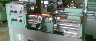
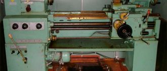
Considering the specific use of the P105 machine, we can say that it has a fairly simple device. The headstock and tailstock are mounted on the frame, as is the electric motor of the mechanism. A horizontally positioned cutter can perform milling work, which significantly expands the scope of application of the machine.
The integral frame of this device is rather an advantage, since it guarantees high stability. Torque is transmitted via a belt drive with a power of 0.4 kW. The electrical equipment of the machine is designed to operate from a network with a voltage of 220 or 380 V. The specific type of network depends on the modification of the device.
The disadvantages of the machine include the need to manually feed the caliper and the inability to create threads. In addition, to work effectively with the device, you need to have a table. The number of speeds provided by the device is 2. The speed range is 1400 and 2000 (per minute). The speed change mechanism is based on the movement of the belt along the pulley shaft.
Another disadvantage of this device is the design of its tool holder. The problem is quite serious, and often leads to the installation of a homemade tool holder on the unit, which copes with fixing the tool better than the factory analogue.
Design features, passport
Advantages of the machine:
- The R-105 lathe has a very simple design due to the specific application. The electronic motor and the headstock and tailstock are located on the bed; The cutter is installed horizontally, which facilitates the execution of milling work and increases the scope of application of the equipment.
- The integral frame of the model guarantees high stability. The transmission of torque is determined by a belt drive with a power of 400 W. The machine operates on electricity, the voltage of which is 220 V or 380 V. The P-105 modification affects a certain type of electricity.
Disadvantages of the machine:
- The caliper must be fed manually; threads cannot be created. To fully operate the machine you need a table. The model provides only two speeds and 1400-2000 rpm. To change speed, you need to move the belt along the pulley shaft.
- The factory cutter holder often fails to fix the cutter, so it becomes necessary to install a homemade one.
You can download the machine passport for free from the link - Passport for the R-105 lathe
Main nodes
- Lid.
- Belt.
- Screw.
- Bed.
- Spindle group.
- Screw.
- Spindle.
- Center.
- Cartridge.
- Drive unit.
- Electrical unit
- Remote Control.
- Key.
- Caliper.
- Milling head.
- Shield.
- Handle (2 pcs.).
- Tool holder.
- Handwheel.
- Steering wheel.
- Tailstock.
- Ground bolt.
- Pulley.
- Screw.
Electrical diagram
Upgrade options
Owners of a lathe model P-105 are trying to improve the tool holder. These days, you can purchase both a circuit diagram and an industrial assembly product. An improved model of the tool holder improves the fixation of the tool and allows the installation of two cutting tools at once.
You can also improve the guides with minor changes, namely grinding, which more accurately processes workpieces. Drastic intervention includes replacing entire rail sets, after which the machine acquires numerical control.
You can remake the electrical system in two ways: the power supply from one phase is 220 V, and from three - 380 V. The second option is most often found on the market, so turners themselves improve the system for electrical supply and starting the engine.
Replacing the main drive motor is determined by altering the console circuit with the addition of a separate rotation unit on top, which will increase the maximum diameters of the treatments.
But to do this, it is necessary to replace the main structure, since the electric motor must be located on a separate platform, not included in the equipment housing. Some lathes also replace the spindle mount.
The most severe modernization is the feed drive motors: the R-105 is transformed into a mini CNC machine. Each master chooses the scheme himself, depending on the processing needs.
Application of model P105
The specialization of the P105 significantly limited its capabilities when solving purely turning tasks. In the factory configuration, the machine can be used for turning metals, wood, and plastics. The low drive power of the main movement of the machine does not allow removing a large amount of metal in one pass. It is also impossible to turn cones, thread cutting, or process large workpieces. The turning spindle does not have a through hole, which makes it impossible to clamp bars through the chuck. The milling head allows you to make grooves on the surface of cylindrical products made of soft materials. It cannot be used for processing steel. The same is true for full milling. A significant number of shortcomings are partially offset by the high strength and durability of the machine.
You shouldn't expect outstanding results from the P105. The design features will not allow you to create complex parts. The prerogative of a lathe is products of small diameter up to half a meter in length.
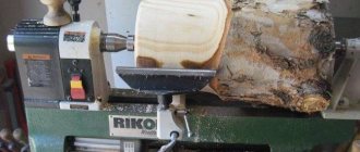
Homemade machine P105
Lathe P105 in production
Some of the shortcomings can be corrected by improving the design. If mandatory milling of grooves is not required, it is better to dismantle the milling head. A weak engine will still not allow you to perform any serious operations. It is recommended to install a more powerful main drive motor. The use of a frequency converter with single-phase power will increase the range of rotation speed control, and will also allow you to connect the machine to a household power supply. On the mechanical side, the toolholder should be replaced and the tailstock adjusted. Additionally, it is recommended to upgrade the turning spindle and cross feed mechanism.
Operating procedure
The position of the tailstock 22 must correspond to the length of the anchor shaft for grooving the collectors; the headstock must be well secured with the lever clamp handle and adjusted with a screw to the desired cutting depth, then secured with a lock nut. Center the anchor shaft before milling, first spreading the jaws of the chuck 9.
To prevent the spindle from turning on, it is important to place the milling head in the working position. In this case, the microswitch contacts on the head bracket will switch the electrical circuit so that only the milling motor is turned on and off.
For milling feed, the longitudinal feed handwheel requires 20 revolutions. With commutator groove, the feed is 7.5 cm/rev. During milling, the armature is rotated and set manually. After the procedure, you need to clean the collector with sandpaper.
Key 13 secures the chuck flange into the hole in the spindle 7 cone and presses it out from there, controlling the chuck cams.
Equipment design
The specific tasks of processing electric machine armatures forced the developers to turn the P105 into a turning and milling machine. Along with the classic units, it is equipped with an additional milling head mounted on the support. The head has height adjustment. The cutter is attached directly to the electric motor shaft, without the use of any gears.
The design of the frame is solid cast, closed type. Electrical equipment and the main motion electric motor are installed in the internal volume. The chuck mounting axis is mounted in the vertical boss of the frame. The torque from the motor shaft is transmitted to the spindle using a V-belt drive. The pulleys have two grooves of different diameters, which provides two speeds of rotation of the workpiece. The use of three-phase motors requires an appropriate electrical supply to the workshop.
The spindle is equipped with a Morse taper No. 4, into which a three-jaw chuck is installed as standard. To clamp long workpieces, the machine is equipped with a tailstock, the quill of which is bored to a Morse taper No. 2.
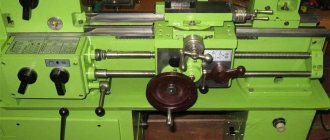
Design of the P105 lathe
The caliper moves along two axes on steel dovetail guides. The longitudinal feed drive uses a rack-gear pair, and the transverse feed drive uses a screw-nut. Both feeds are equipped with manual handwheels only. The upper slide is not included in the design of the equipment. The length of the longitudinal guides provides the greatest caliper travel of 500 mm, which significantly exceeds the performance of models of a similar class. In this case, there is a restriction of movement towards the spindle. The caliper does not reach the chuck by a distance of approximately 50 mm, which is due to the original purpose of the machine.
Specifications
| Are common | |
| Frequency range: | 36.0 - 46.1 MHz |
| Years of manufacture: | 1967-1986 |
| Compliance: | GOST MOROZ-4 (domestic military standard), exceeds the standards of GOST 12252-86 |
| Frequency step: | smooth tuning, scale at 25 kHz |
| Frequency display: | optical scale |
| Total frequency setting error on the scale at 20°C (±5): | after 5 minutes of warm-up does not exceed 4 kHz |
| Radiation type: | FM |
| Antenna connector type: | for Kulikov antenna, bayonet |
| Antenna resistance: | 1-2000 Ohm |
| Power supply type: | 4 batteries KN14 or 2 batteries 2NKP-20 (or 2NKP-24) |
| Supply voltage: | 4.4 - 5.2 V (2 x 2.4 V) |
| Current consumption: | • receive 0.85 A • transmit 1.85 A • transmit in remote mode 2.2 A |
| Battery life (receive:transmit = 3:1): | • 12 o'clock. with KN14 • 17.5 hours. with 2NKP-20 • 21.5 hours with 2NKP-24 |
| Communication range when using a 1.5 m pin antenna using a three-beam counterweight: | at least 6 km, for a 2.7 m rod antenna - at least 10 km, and for a traveling wave antenna - at least 25 km |
| Deployment time: | • when working on a whip antenna - 5 min. • when working on a beam antenna - 15 min. |
| Operating temperature range: | –40 ~ +50 °C |
| Dimensions: | • radio station (with protruding parts) - 310 x 325 x 170 mm • stowage box - 620 x 420 x 350 mm |
| Weight: | • working kit r/s - no more than 14 kg • stowage box with kit - no more than 40 kg |
| Transmitter | |
| Type: | smooth local oscillator (LC generator) |
| Output power: | not less than 1 W |
| Maximum Deviation (FM): | ±5 kHz |
| Transmitter modulation input sensitivity: | 140 mV |
| Receiver | |
| Type: | single conversion superheterodyne |
| Intermediate Frequency: | 793.8 kHz |
| Sensitivity: | no worse than 1.5 µV at signal-to-noise ratio 10:1 |
| Selectivity for mirror channels: | not less than 54 dB |
| IF selectivity: | not less than 80 dB |
| Bandwidth at 6 kHz: | 14 kHz |
| When the input voltage changes from 3 to 1000 μV, the output voltage changes: | no more than 20% |
| AFC time constant: | 0.1 C |
| Output voltage of the low-frequency path of the receiver at a signal voltage at the input of 1.5 μV and a frequency deviation of 5 kHz on a load of low-impedance TA-56M telephones: | not less than 1 V |
| Output voltage of the low-frequency path of the receiver in the absence of a signal (noise voltage): | 0.75 V |
Functions, capabilities, controls, etc.
Radio stations R105M, R108M, R109M are assembled using a transceiver circuit. Common elements for the receiver and transmitter are: antenna circuit, local oscillator, ULF, power supply. The receiving part of the radio station has 2 resonant UHF stages on 1ZH17B and 1ZH18B lamps, a mixer on a 1ZH18B lamp, 4 identical IF stages on 1ZH18B lamps, an amplifier-limiter on a 1ZH18B lamp, and a frequency discriminator on 2D401 diodes. The receiver local oscillator is assembled on a 1Zh18B lamp and has a smooth adjustment by changing the capacitance. The same generator is used as a master generator during transmission. At reception, an additional capacitance is connected to the master circuit. The circuit of this generator also includes a D901 varicap, which is used to modulate the frequency during transmission and the automatic frequency control during reception. When operating for transmission, the signal from the master oscillator is sent to a power amplifier using a 1P24B lamp. Low frequency amplifier - 2 cascade, with MP15 transistors, used during transmission as a modulation signal amplifier. All variable capacities, except for the capacitance of the antenna circuit, are installed on the same axis, and are adjusted simultaneously with the change in the frequency of the master oscillator-heterodyne. As the final low-frequency device, a microtelephone headset is used, consisting of a DEMSH1A microphone, a P15 transistor microphone amplifier and headphones, or a handset with a MK-10-MB powder microphone and a TK-47-130 telephone capsule.
The radio stations provide reliable two-way radio communication with a radio station of the same type in moderately rugged and forested terrain, at any time of the day or year, at any frequency range with a battery voltage of 4.4 - 5.2 V at distances: • when working on the move with a whip antenna height 1.5 m or on the ground to the same antenna with a counterweight - 6 km; • when working in a parking lot with a combined 2.7 m antenna and counterweight - 10 km (for P-105M - 8 km); • when working in a parking lot with a directional beam antenna suspended at a height of 1 m above the ground - 15 km; • when working on a beam antenna raised at the radio station to a height of 5-6 m above the ground - 25 km; • when working on a beam antenna from shelters with a depth of no more than 3 m with an overlap of at least 1 m thickness - 15 km; • when working from a remote point through a TA-57 telephone set connected to the radio station with a two-wire field cable up to 500 m long, to a combined antenna 2.7 m high - at least 10 km (for R-105M - at least 8 km), at a beam antenna suspended at a height of 1 m - no less than 15 km, raised by 5-6 m - no less than 25 km. In this case, switching the radio station from reception to transmission and communication is carried out directly from the telephone.
The radio station has the following types of antenna devices: • flexible whip antenna 1.5 m high (using a counterweight of 3 beams); • a combined antenna consisting of a flexible whip antenna and 6 elbows (total antenna height - 2.7 m), using a counterweight of 5 beams - for operation in a parking lot; • on-board antenna, consisting of a combined whip antenna, a special bracket with a shock absorber for mounting the antenna on board the vehicle and a connecting conductor 1 m long - for operation while the vehicle is moving; • directional beam antenna 40 m long, suspended at a height of 1 m above the ground - for operation at extended ranges and from shelters; • an elevated antenna, consisting of a beam antenna 40 m long, raised at the radio station to a height of 5-6 m, with a gradually lowering opposite end directed at the correspondent - for working at increased ranges and from shelters.