Machine speed boxes features, varieties
On metal-cutting machines there is a need to change the spindle rotation speed, while changing the force of its torque. Depending on the various metal processing operations, different rotation speeds and forces are required. To adjust the required rotation in machines, special devices are used, consisting of sets of shafts with gears. Such devices are called gearboxes and feedboxes.
Transmissions can be divided by shift type. There are different types of switching, but only two types are the most common.
— The first type is switched by sliding shafts with gears.
— The second type is switched using cam or friction type clutches.
Boxes switched by shafts with gears
This type of machine gearbox is the most common in modern machine tools. In this box, speed changes occur using blocks. Typically, several gears are connected into one unit, which slides along a shaft. Typically three gears are used in one unit, sometimes four gears may be used. When sliding along the shaft, different gears with different gear ratios engage. By changing the gear ratios, the spindle rotation speed changes.
Boxes switched by claw clutches
In this type of box, sets of shafts with gears of different diameters are also used. But unlike sliding blocks, the gears here are located motionless on the shafts. In addition, the gears are in constant engagement with others, and a shaft rotation connection is used to switch gear modes. Different shafts rotate at different transmission speeds, so by connecting one or another shaft, the spindle speed also changes. The shafts are connected using a claw coupling mechanism. The clutch with cams can perform sliding and translational movements, while when moving to the right, the right shaft is connected, and when moving to the left, the left shaft is connected. The cams are a solid design. They can transmit significant forces. But there is one peculiarity: switching speed with a cam clutch can only be done when the rotation is turned off, otherwise the cams may fail.
Boxes switched by friction type clutches
Unlike the rigid clutch of cam clutches, with the help of friction clutches the clutch can be transmitted more softly. Friction clutches use special discs that are pressed against each other using powerful springs. When compressed, significant friction is created between the discs, which can transmit large forces. At the same time, there are no sharp shocks during switching on, because the discs slip and soften the force. Thanks to this, the box with friction clutches can be switched while the machine is rotating. Especially often in machine tools, friction clutches are used to switch the types of spindle rotation from direct to reverse, and vice versa. If the discs slip significantly, the clutch must be adjusted and tightened.
Source
Main technical characteristics
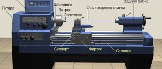
A screw-cutting lathe has a number of technical characteristics that you should focus on when choosing a machine both for production and for a personal small workshop.
Number of revolutions
The number of revolutions may vary depending on the size and purpose of the lathe, but the maximum number of revolutions is 2000 rpm.
Larger speeds are for thin holes in small parts. For personal purposes in a small workshop, a machine that operates at a speed of 1000 rpm is sufficient.
Accuracy class
There are several classes of machine precision. For processing small parts and on an industrial scale, high-precision machines marked P are used.
For everyday use, machines with a normal level of accuracy, which are marked N, are sufficient. There are special classes of accuracy that are used only in very large industries. This is indicated by the letters B, C.
Table of contents
The gearbox of a lathe refers to the main parts of the spindle drive. It is created to transfer the energy of movement of the electric motor to the remaining parts of the mechanism. It is also used to change the spindle speed and, accordingly, the operating speed. Depending on the design of the machine, there can be two types of placement of this unit. The box can be built into the spindle head housing or mounted in a separate housing unit, which must still be connected to the spindle.
If the gearbox of a screw-cutting lathe is built-in, then this makes the design significantly simpler, this is especially noticeable in terms of installation. This greatly simplifies device management. At the same time, they create conditions for an increase in temperature during the working process, and also create additional vibrations. Thus, they are used only in normal precision models, since precision machines use the split-box operating principle.
photo: lathe gearbox
The speed can be changed in a stepless or stepwise manner as well as reversing. Several methods are used for this, for example:
Gearbox device
The gearboxes of metal-cutting machines can differ markedly from each other. Using the example of a device such as a 1M61 lathe, we can consider the components of the equipment. This includes things like:
Operating principle of the gearbox
The gearbox of a 16K20 lathe operates on a gear block. Switching of these blocks is carried out using a special handle, which transfers the gear from one area to another. The spindle head receives rotational motion of a given speed from the gears, which transmit this through a gear coupling. The handle turns the clutch on and off, thereby regulating the speed. The adjustment takes place in two directions, in which the lead screw rotates, so that you can increase and decrease the rotation speed with one control element.
Basic movements
The rotary cutter gearbox itself remains stationary during operation, but its internal parts, such as the belt drive, can move. Movements take place in the longitudinal plane, depending on where exactly the control handle is directed. Transmission moves from one sector to another, increasing or decreasing speed.
Adjusting the gearbox of a lathe
Gaps. With active use of equipment, gaps appear near moving parts over time. This not only reduces the accuracy of the equipment, but can also lead to breakdown. The machines provide for the adjustment of such connections, which consists of fixing the main fasteners in position at the proper distance. For this, wedges, nuts and bolts and other elements are used.
Clutch adjustment. One of the main elements that the 1K62 lathe gearbox has is the coupling located on its main shaft. Due to the friction that occurs during operation, its disks are subject to severe wear over time. To adjust it, use pressure nuts that are screwed onto the ring. After pressing the latch into the ring, you can turn the nuts until they stop. When the clutch is fully adjusted, it starts without jolts or sudden movements.
Backlash adjustment. If play appears during operation, it should be eliminated. To do this, you need to disassemble the box with the machine turned off, place the parts in the correct position and fix them. During operation, vibration will cause play to appear periodically and this is quite normal, so you should be careful to eliminate it in time.
Repair of lathe gearbox
Source
Classification methods
Screw-cutting lathes are divided into several types. There are several most popular characteristics by which machines of this type are classified.
Weight
There are small machines that are convenient to use in a personal workshop or large ones that are intended for industrial production.
Large and heavy turning devices are mainly intended for use in mechanical engineering and energy. Heavy machines – over 40 tons in weight.
The lightest ones weigh no more than half a ton. Each type of mass has its own characteristics:
- Lungs. As a rule, the cross-sectional diameter in such equipment is no more than 500 mm.
- Machines weighing up to 15 tons are considered medium and they do not process parts with a diameter greater than 1250 mm.
- 15-400 tons. Rarely found with high accuracy rates. Typically this is Class H equipment.
Maximum part length
This parameter is determined by the distance between the centers of the machine. With equal diameters of manufactured products, there are machines capable of processing long and short workpieces.
Max diameter
According to the maximum diameter, there is the most extensive classification of parts. They start from 100 mm and go up to 4000 mm. In addition to the above indicators, a parameter such as productivity is often used for classification.
There are machines for small-scale production, for medium-scale production and for large industrial scales. The latter option is used on conveyor lines.
Types of gearboxes
A gearbox is a mechanism designed to stepwise change the frequency (speed) of rotation of the driven shaft at a constant speed, leading by changing the gear ratio. Changing the rotation speed is achieved by including various gear kinematic pairs between the shafts. The gearboxes must provide the calculated range of spindle rotation speeds in accordance with GOST 8032-56.
The gearboxes are compact, easy to operate and reliable in operation. The disadvantages of gearboxes include the difficulty or impossibility of stepless control of rotation speeds, the occurrence of vibration and noise at some frequencies. There are a large number of different designs of gearboxes, but they are all a combination of individual standard mechanisms.
According to the layout, the gearboxes are divided into gearboxes with gears built into the spindle headstock, and speedboxes with a separate drive, when the spindle headstock and the gearbox are made in the form of separate units connected by a belt drive.
According to the switching method, gearboxes are available with replaceable gears between the shafts and a constant center distance, with movable wheels or wheel blocks, with wheels and cam clutches that cannot be moved along the shafts, with friction clutches, with electromagnetic clutches and with combined switching. The gearboxes are made in a closed housing, the gears operate in an oil bath. This design protects the mechanisms from contamination, provides abundant lubrication and good cooling of the mechanisms, and increases the efficiency of the gearbox.
Gearboxes with movable gear units can transmit large torques with relatively small radial dimensions of the gears. In addition, in such boxes only those gears that transmit the power flow are in mesh. The remaining wheels do not wear out at this time. These advantages make it possible to widely use movable blocks of gear wheels to change the spindle rotation speed. As a rule, spur wheels are used in mobile units. The disadvantages of these gearboxes include the inability to switch blocks on the go; the need for blocking, preventing the possibility of simultaneous activation of gear blocks, the joint operation of which is not intended; relatively large axial dimensions.
Gearboxes with cam clutches are distinguished by the fact that they have small axial movements of the clutches and lower shifting forces than those of mobile wheel units. Gearboxes with dog clutches can use helical and herringbone gears. At the same time, cam clutches do not allow changing gears on the fly with a large difference in spindle speeds; they are characterized by power losses due to the rotation of an idle pair of wheels and their wear.
Gearboxes with friction and electromagnetic clutches allow you to quickly and smoothly change gears on the go and under load. The disadvantages of such gearboxes are the loss of power due to the rotation of an idle pair of wheels and their wear; large radial and axial dimensions of couplings for transmitting large torques; decrease in machine efficiency due to friction in disconnected clutches; heating of couplings; the need for their frequent adjustment, heat transfer from the couplings to the spindle assembly. Combined gearboxes contain mechanisms with movable blocks, claw couplings, and selector devices.
Gearboxes with replaceable gears are used for stepwise control of the output shaft speed.
The diagram of a two-shaft box with a sliding block of gears z1 and z3 located on shaft I with splines is shown in Fig. 50, a. Gears z2 and z4 are mounted motionless on shaft II. The distance between the wheels z2 and z4 should be slightly greater than the length I of the movable wheel block, while the gear wheels z1 and z2 and the wheels z3 and z4 are disengaged. When switching gears, an indispensable condition is to stop them.
The second gearbox design for two rotation speeds (Fig. 50, b) contains a cam clutch sliding along a key or in splines. Wheels z1 and z3 are mounted motionless on shaft I and are in constant engagement with wheels z2 and z4, which have cams (gears) and sit freely on shaft II. The pairs of gears z1/z2 and z3/z4 are engaged by moving the claw clutch. Instead of a dog clutch, cone or multi-plate friction clutches can be used. The design of the gearbox (see Fig. 50, a) has become widespread due to its simplicity and reliability in operation. A gearbox with clutches (see Fig. 50, b) has disadvantages due to the complexity of the design, less reliability in operation and more intensive wear of gear wheels that are in constant mesh.
The circuit for three rotation speeds is shown in Fig. 50, c. The circuit for four rotation speeds is shown in Fig. 50, g. On shaft I there are two movable blocks, consisting of wheels z1 and z3, respectively; z3 and z7, on shaft II there are fixed gears z2, z4, z6, z8. The movement of the blocks ensures the engagement of gears z1 with z2; z3 with z4; z5 with z6; z7 with z8. A feature of this scheme is the need to provide a lock, which will eliminate the possibility of simultaneous activation of two pairs of wheels. One of the variants of the locking mechanism, consisting of two disks A and B with cutouts. The locking device can be structurally implemented in other ways, both mechanically and using hydraulics.
The variant of a three-shaft gearbox for four rotation speeds (Fig. 50, d) consists of two sequentially located elementary gearboxes for two rotation speeds.
Schemes of four-shaft gearboxes (Fig. 50, f, g, h) are more complex in their structure. In the gearbox diagram (Fig. 50, h), two upper subranges of rotational speeds are formed when shafts II and IV are connected by a clutch:
and the two lower ones - through single gears between shafts II and III and shafts III and IV:
Step regulation can also be carried out using replaceable gears z1 and z2 at a constant distance A between shafts I-II (Fig. 50, i).
The considered scheme allows for reduction to obtain four different output shaft speeds, and with the use of an asynchronous two-speed or adjustable DC motor, the control range of the gearbox is significantly expanded.
Automatic gearboxes . To carry out a continuous cutting process with constant power and speed when changing the spindle speed in all subranges (which is most important in face turning), gearboxes with automatic stage switching (AKS) using electromagnetic or hydraulic couplings are used. AKS boxes are available in several standard sizes and are used in a number of CNC machines. Unified AKS gearboxes are intended for use in the main, movement and feed drives of metal-cutting machines of lathe, drilling, boring and milling groups, as well as for use in some other machines. The AKS drive provides stepwise control of the spindle speed over a wide range with almost constant power.
Unified gearboxes allow you to concentrate all drive control operations using a mechanical transmission: starting, braking, reversing, speed control. They provide high speed transient processes, the ability to switch during operation, protect drive parts from overloads and have a number of other advantages compared to gearboxes with movable gear units . The AKS uses normalized electromagnetic couplings with magnetically conductive disks with contactless current supply. The AKS range includes seven sizes (0–6) with power from 1.5 to 55 kW.
Remote control of the AKS drive is carried out using a contactless thyristor control system.
The kinematic diagram of the main movement drive of the 16K20FZS4 machine with AKS is shown in Fig. 51. Rotation of the spindle is transmitted from an asynchronous electric motor (power P = 10 kW and n = 1460 rpm), placed inside the base, using V-belts 53 and electromagnetic clutches EM to the input shaft I of the automatic transmission (AKS), from the output shaft III AKS with the help of a toothed chain or V-belts of rotation is transmitted to the input shaft of the IV spindle head. The spindle head provides for manual switching of two rotation speed ranges with a ratio of 1:3. According to the program, the AKS has nine rotation speed values, and in the spindle head, due to manual switching of the z43 and z60 gear unit, it doubles, which together provides 18 spindle speeds in the ranges from 35 to 1600 rpm (nine frequencies in each range). The AKS are controlled from the control panel of the EM907 CNC system. The switch on the control panel in automatic mode is set to the “Automatic” position.
To carry out thread cutting on machines 16K20FZS4 and 16K20FZS5, the circuit includes a BE-51 sensor. Shaft VII receives rotation from the spindle through a 60/60 backlash-free gear train with a gear ratio of one.
Source
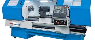
Overview and diagrams of common models
Among the diverse model range and several generations of machines that are produced by our production, there are several models that continue to be popular for their technical characteristics and universal properties.
All of them are used in production or in domestic conditions to this day. At the same time, they continue to be worthy competitors to foreign analogues.
These are reliable, durable and durable devices capable of performing a huge number of different functions.
1L532
One of the most popular machines in the former USSR, which can successfully process workpieces of medium and large sizes.
At one time, this equipment was successfully exported to many countries around the world. Accuracy class – N. Machine weight – 43 tons.
16U04P
High precision equipment. The largest diameter of the part processed above the bed is 200 mm. Machine weight – 750 kg.
1P611
A machine used in production, including for turning wheels of railway vehicles. According to GOST, they are distinguished by increased accuracy and have the ability to brake the spindle. Device weight 560 kg. Easily performs the following functions:
- Drilling.
- Segment.
- Cutting internal and external threads.
- Treatment of various surfaces.
The largest diameter of the workpiece above the bed is 250 mm.
1D601
This machine is better suited for purely domestic use. The accuracy is lower than the previous machine. It features high performance even after many years of operation.
Moving the caliper is only possible manually. The weight of the entire machine is about 30 kg. Due to the small dimensions, the maximum length of the workpiece to be processed is 18 cm.
16K40
One of the most popular models that has really gained popularity among craftsmen. Belongs to the middle class of equipment with accuracy class N.
Since 1932, several tens of thousands of various screw-cutting lathes have been produced in the USSR. They were used not only in production, but also for training young people, in schools, colleges, and many had desktop machines in garages, homes, and their own workshops.
Such equipment will help to bore a hole, level the required surface, or drill an existing hole. It is important, focusing on the initial specifications of the equipment, to purchase the most suitable model.
Feed box design for lathe 1k62
The purpose of the feed chain of a screw-cutting lathe is to ensure mechanical movement of the cutter mounted on the support relative to the rotating workpiece during turning. Modern universal screw-cutting lathes have a feed box , which is usually mounted on the bed below the headstock.
The feed box is used to switch the rotation speed of the lead screw and the lead shaft, i.e., to select the feed speed of the cutter along the spindle axis. For example, when cutting a metric thread with a pitch of 1 mm, the feed box mechanism must ensure that the cutter moves (feed) along the workpiece by 1 mm per spindle revolution.
Inside the feed box there is a gearbox, which consists of switchable gears. The input shaft of the feed box receives torque from the spindle through replaceable gears (guitar). At the output of the feed box there is usually a drive shaft and a lead screw, the torque from which is supplied to the caliper apron.
When cutting threads, the feed box transmits rotation to the lead screw; When turning and cutting face (flat) threads, a roller is used.
Using a lead roller for feed during turning allows you to maintain the accuracy of the lead screw longer, which is necessary when cutting threads.
Replacement gears (guitar) are used only when the required feed cannot be achieved by switching the feed box handles.
The source of movement (initial link) of the feed chain is the spindle, therefore the feed speed in screw-cutting lathes is measured and indicated in millimeters per spindle revolution (mm/rev).
The feed mechanism must allow:
General view of the feed box assembly
Photo of the feed box
Purpose and scope of application of a universal metal machine
Parts processed by universal screw-cutting lathes are mainly made of ferrous and non-ferrous metals.
Turning cones and threading are additional functions of the machine. If the kit includes additional tools and drills, then the functionality of the machine is even greater.
Since these machines have large dimensions and impressive weight, they can rarely be found in private workshops. Areas of application:
- production of small series of products;
- single production and processing of parts;
- in rare cases - mass production.
But on an industrial scale, screw-cutting lathes are rarely used.
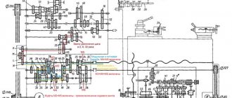
Kinematic diagram of screw-cutting lathe 1K62
The spindle is reversed by moving the coupling 97 to the right. Then the rotation from shaft II to shaft III is transmitted through gears 22-23, 24-12 and further along the previous chain. The number of gearing options is 15, the actual values of rotation speeds are 12, since the gear ratios of some options are also numerically the same.
Feeding movement . The feed mechanism includes four kinematic chains: screw-cutting, longitudinal and transverse feed, and a chain of accelerated movements of the caliper. Rotation to shaft VIII is transmitted from spindle V through gears 25-26, and when cutting threads with an increased pitch - from shaft VI through the step increasing link and then through gears 27-28. In this case, the step increasing link can provide four gear options:
Screw chain . When cutting threads, the caliper is fed from the lead screw 68 through the uterine nut fixed in the apron. For cutting metric and modular threads, the screw-cutting chain is installed according to the first option, and for inch and pitch threads - according to the second. Changing the thread pitch is achieved by switching the gears of the pitch increasing link, the Norton mechanism, blocks 61-63 and 67-66 and installing replacement wheels on the guitar. When turning and cutting metric and inch threads, replaceable gears 39-43-40 are in mesh, and when cutting modular and pitch threads - 41-43-42.
In special cases, when cutting high-precision threads, to eliminate the influence of errors in the kinematic chain, the latter is shortened by including couplings 98, 99 and 101, as a result of which shafts X, XII and XV form, together with the lead screw 68, a single rigid connection. A screw-cutting chain for cutting threads with different pitches is adjusted in this case only by selecting replacement wheels on the guitar.
Longitudinal and transverse feed of the caliper. To transmit the rotation of the apron mechanism, the running shaft XVI is used. A gear 72 slides along it along the keyway, transmitting rotation from shaft XVI through a pair of gears 73-74 and a worm pair 75-76 to shaft XVII.
To obtain the longitudinal feed of the caliper and its reversal, one of the cam clutches - 102 or 103 is turned on. Then the rotation from shaft XVII is transmitted by gears 77-78-79 or 80-81 to shaft XVIII and then by a pair of 82-83 - to rack and pinion wheel 84. Since the rack 85 is fixedly connected to the machine bed, the rack wheel 84, rotating, simultaneously rolls along the rack and pulls the apron with the caliper.
Transverse feed and its reversal are carried out by turning on clutches 104 or 105. In this case, through gears 77-78-86 or 80-87, rotation is transmitted to shaft XIX and then through gears 55-89-90 to screw 91, which imparts movement to the transverse support.
Caliper rapid movement chain. To carry out the accelerated (installation) movement of the caliper, the running shaft XVI is given rapid rotation from the electric motor 92 through the V-belt drive 93-94. In this case, the caliper feed mechanism through the feed box does not need to be turned off, since an overrunning clutch 106 is installed in the drive chain of the drive shaft. Using screw pairs 95 and 96, you can manually move the cutting slide and the tailstock quill.
Feed box design of screw-cutting lathe 1K62
The headstock mechanism allows:
The feed box receives movement from the headstock output shaft through replaceable triplane gears.
The feed box mechanism allows you to obtain all types of threads and required feeds provided for by GOST.
Through a lead screw with a pitch of 12 mm (without a pitch increasing link), the following threads can be obtained:
Using the mechanism for increasing the pitch, at spindle speeds from 12.5 to 40, it is possible to obtain threads with an increased pitch (32 times greater than normal, and at speeds from 50 to 160, 8 times in accordance with the data in the table on handle 20 (see Fig. Fig. 5).
Through the running roller, the caliper at any number of spindle revolutions receives longitudinal feeds from 0.07 to 2.08 mm/rev and transverse feeds from 0.035 to 1.04 mm/rev, and at speeds from 50 to 630 per minute, longitudinal feeds from 2. 28 to 4.16 mm/rev and transverse from 1.14 to 2.08 mm/rev.
To cut more precise threads in the feed box, the position of the handle 19 is provided in which the lead screw is engaged directly, bypassing the feed box mechanism. In this case, the required pitch is selected using interchangeable gears of a special set.
By turning handle 20, the choice of a number of threads or feeds is selected. To obtain the required value from the selected row of threads or feeds, you need to pull the drum disk towards you by the handles, turn until the notches of the disk coincide with the notch of the drum, and then move the disk forward to its previous position
To carry out rapid movements of the caliper, an overrunning clutch is mounted in the feed box on the output shaft.
Rice. 7. Directions for transmitting motion through the feed box when cutting various threads and providing longitudinal and transverse feeds.
Feed drive
The feed motion is borrowed from the spindle shaft (VI) through the 60/60 guitar gears. Further, from VII to VIII shaft, the movement is transmitted through a reversing mechanism (42/42 or 28/56 or 35/28/35). From shaft VIII to shaft IX, movement is transmitted through replaceable gears (42/95/50 or 64/95/97). Wheel 35 rotates together with shaft IX, from which the movement branches into two directions (see Fig. 7): in the first direction, rotation is transmitted when cutting inch and pitch threads, and in the second direction, metric, modular and providing longitudinal and transverse feeds.
The first direction of rotation transmission . Clutch M2 is disengaged and from wheel 35 the movement is transmitted through wheels 37/35 to shaft X, from which the captive mobile block of wheels 25–36 receives rotation through wheels 28/25. Wheel 36 of this block can be meshed with any wheel of a seven-speed block of 16 gears (Norton cone) (48,44,40,36,32,28,26), which in turn will lead to rotation of shaft XI, and with it the wheel 35 (clutch M3 is turned off at this time). Next, the movement is transmitted by wheels 35/28, 28/35 (two wheels 28 are mounted on a common bushing, but they do not transmit rotation to shaft XIII - they rotate freely on the shaft). Clutch M4 is turned off (it connects the rotation of shafts X and XII when transmitting rotation in the second direction). From wheel 35, rotation is transmitted to shaft XII, together with which the wheel block 18–28 rotates. From shaft XII to shaft XIII, motion can be transmitted through 18/45 or 28/35 wheels. Next, a pair of 35/28 or 15/48 wheels is used from shaft XIII to shaft XIV. Shaft XIV is connected to shaft XVI when the M5 coupling is engaged and, thus, the lead screw t = 12 mm receives rotation.
Second direction of rotation transmission . clutch M2 is engaged, at the same time wheel 35 located on shaft X is disengaged, and the seven-speed gear block receives rotation. From this block, the movement is transmitted to the coupling block of wheels 36–25, then to shaft X through wheels 25/28, while the M4 clutch is engaged (when the right coupling half is moved to the left, wheels 35 and 28 are disengaged) and therefore shaft XII rotates integrally with the shaft X. Next, the movement is transmitted in the same way as described above: from shaft XII to shaft XIII, and from there to shaft XIV. Moreover, when cutting metric and inch threads 17, the rotation in the guitar is transmitted through replaceable gears 42/95/50, and when cutting modular and pitch threads, the replaceable blocks are turned over and then the rotation will be transmitted through gears 64/95/97. When cutting threads, the movement is transferred to the lead screw, and to obtain longitudinal and transverse feeds, the M5 clutch is disconnected and the XV shaft receives rotation through the 28/56 double-crown wheels and the Mo overrunning clutch. When wheels 28–28 are shifted to the left, its left gear rim engages with wheel 56, rigidly mounted on shaft XV, and rotation is transmitted to the latter in addition to the overrunning clutch, which is necessary when cutting end threads.
The feed box makes it possible to cut all standard threads and provides the necessary feeds, the values of which are indicated in the technical specifications of the machine.
From the running shaft XVII, through the wheels 27/20/28, the safety clutch MP and the worm pair 4–20, the shaft XIX rotates (see Fig. 5). The latter is connected by the front gear 40 directly to the toothed rims of the cam clutches M7 and M9, and by the rear gear 40 through the idler wheel 45 with the toothed rims of the M6 and M8 couplings. To communicate longitudinal feed to the caliper with handle 14 (see Fig. 1), the M7 clutch is engaged, then from shaft XIX to the rack and pinion wheel Z = 10; m = 3 rotation is transmitted through gear pairs 40/37 and 14/66. To communicate the cross feed forward and backward to the caliper, the M9 and M8 clutches are activated, respectively. When controlling the caliper feeds, the principle of mnemonicity is implemented, i.e., the direction of tilt of the handle 14 corresponds to the direction of the caliper feed.
When performing turning operations, the kinematic feed chain coordinates the rotation of the spindle with the movement of the support in the longitudinal or transverse directions: for 1 revolution of the spindle, the support must move by an amount S.
The ECB of the longitudinal feed chain has the form:
(3) S = 1rev.shp inn π m z mm/rev
where: inn – gear ratio of the feed drive from the spindle to the rack wheel;
π·m·z mm/rev – length of the pitch circle of the rack and pinion wheel;
The UKB for the chain of minimum longitudinal feed will be written as follows:
Fast (auxiliary) movements of the caliper are communicated from a separate electric motor M2, (N = 1 kW, nM2 = 1410 rpm) (see Fig. 5), through a belt drive, a running shaft and then along the above-mentioned kinematic chains of the apron mechanism. The presence of an overrunning clutch M0 at the left end of the drive shaft allows it to be given a higher rotation speed (from the electric motor M2) without turning off the working feed. The M2 engine is turned on with button 13.
Setting up a thread cutting machine
When cutting a thread, in one revolution of the spindle, the support (cutter) must move by the thread pitch Pp. The UCB of the screw-cutting chain has the following form:
where in.v. – gear ratio of the corresponding screw-cutting kinematic chain from the spindle to the lead screw;
Px – machine lead screw pitch in mm (PX = 12 mm).
Knowing the direction of transmission of motion through the feed box (Fig. 7) and using the kinematic diagram of the machine (see Fig. 5), you can write down the UCB of any screw-cutting chain. For example, for a metric thread with a minimum pitch:
When cutting inch threads, the pitch is specified by the number of threads per inch:
where: k – number of threads per inch of thread (1″ = 25.4 mm).
The UCB chain for cutting inch threads with a minimum pitch has the form:
The modular thread pitch is expressed in terms of the module, i.e.:
The pitch thread is specified by the diametric pitch P. The formula for determining the pitch of the cut pitch thread has the form:
where: P – number of pitches of thread being cut.
The UCB of chains for cutting modular and pitch threads can be written similarly to the above, guided by the information given in paragraph 4.5.3.
Cutting high precision threads and non-standard threads
When cutting high-precision threads, rotation is transmitted directly to the lead screw. For this purpose, gear couplings M2, M4 and M5 are activated, connecting shafts X, XII, XV and the lead screw. In this case, the accuracy of the cut thread is increased by reducing the length of the screw-cutting kinematic chain.
In this case, the UCB of the screw-cutting chain will be written as follows:
where: iШ.Г – gear ratio of the chain from the spindle to the replacement wheel guitar;
ig – gear ratio of the replacement wheels of the guitar.
Solving equation (8) for iг, we obtain the following formula for selecting replacement gears for a guitar:
This formula can also be used when calculating iг in the case of cutting non-standard threads.
Long pitch thread cutting
When cutting threads with a normal pitch (Pp = 1–12 mm), rotation is transmitted to shaft XIII directly from the spindle through 60/60 wheels (i=1). To cut threads with an increased pitch (Pp = 14–192 mm), the Z=45 gear wheel of shaft VIII is engaged with the Z=45 wheel of shaft IV, and rotation must be transmitted to the spindle through the overdrive. Depending on the magnitude of the gear ratio from the spindle to shaft VIII (depending on the position of the selection blocks), the pitch of the cut thread will be increased by 2, 8 and 32 times.
Cutting end threads (Archimedean spiral)
Face threads are used, for example, in self-centering jaw chucks, in which the radial movement of the jaws is communicated by a disk having a thread at the end. Face threads are cut along a chain of inch threads. The chain connects the rotation of the spindle with the rotation of the cross feed lead screw. Tuning is provided by the guitar's interchangeable wheels. Retracting the support (cutter) to its original position to perform a subsequent transition when cutting threads is also performed by reversing the rotation of the spindle. To exclude the overrunning clutch M0 from the chain (see Fig. 7), which transmits motion to the running shaft only during direct rotation of the spindle, one of the wheels of the block 28–28 on shaft XV is engaged with a gear Z = 56 rigidly fixed to the running shaft .