Machine speed boxes
Modern metal-cutting machines are designed in such a way that the rotational movement of their electric motors must be transmitted to the spindle, and this must be done in such a way that it is possible to change the transmitted power, torque and speed within certain limits. This is done using a mechanism called a gearbox .
These designs are quite complex and are quite expensive to produce, but they are used almost everywhere in metal-cutting machines . Their main elements are gears and shafts. It should be noted that the gearboxes of modern machine tools are very compact, easy to control and operate.
The torque at their input comes from a constant speed pulley driven by an electric motor connected to it by a gear, chain, belt or V-belt drive.
In order to change the number of spindle revolutions, several handles are provided in the design of speed boxes (in some equipment models there is only one). Relieving the spindles of this equipment in the case of a gearbox is a significant advantage. Unlike belt drives, gear drives provide a truly rigid kinematic chain of motion that eliminates slippage. This circumstance is very important when carrying out many operations on machines (for example, cutting threads with cutters).
The designs of speed boxes and feed boxes of modern machine tools are very diverse, but in general they are nothing more than a combination of a number of fairly standard and simple parts, mechanisms and assemblies. They are arranged and interact with each other in such a way as to ensure a change in the number of revolutions of the driven shafts (spindles, drive shafts and screws).
In all modern metal-cutting machines, the gearbox is one of their most important parts. With its help, the number of spindle revolutions changes.
All parts and components that make up the gearbox are located in a specially designed and manufactured housing. It is cast from cast iron, and undergoes appropriate processing before assembling the box.
The main functional parts of gearboxes are gear blocks, gears, racks, shafts, gear couplings, handles, etc.
The procedure for switching speeds itself consists of using the handles to change the kinematic conditions in which the gears are located. As a result, the gear ratio and, accordingly, the spindle speed change.
To ensure the ability to switch rotation speeds of the machine equipment spindles, the handles are placed directly on the outside of the box, which provides easy and convenient access to them. These control elements, using levers and other structural elements, are connected to toothed couplings and gear blocks, which directly change the configuration of the gears.
One of the most important parts of gearboxes is the spindle. It is on it that various tools or special equipment are fixed (for example, chucks into which workpieces or parts are clamped). The spindle is the final element of the gearbox design.
From the point of view of the structural diagram of machine tool equipment, gearboxes are drive elements that provide stepwise control of the main movement. They are subject to a number of requirements, among which the main ones are ensuring constant speeds, transfer of forces, ease of control, speed and overall dimensions.
Description of feed box
The feed box is designed to change the amount of working feeds of the table, slide and console and communicate rapid movements to these units.
When describing the kinematic diagram, it was noted that the machines have 18 different feeds. Longitudinal and transverse feeds are the same, while vertical feeds are three times less.
The feed box is an independent unit mounted on the left side of the console, to which it is screwed and secured with two control pins. A feed switch box is flanged to the feed box body, which has a plastic dial in the front part indicating the feed rate and a fungus for switching.
6m82
Feed box
The feed values indicated on the dial refer to the longitudinal and transverse feeds of the table.
Feed switching is carried out in the following order:
- button 6 is pressed and the plastic fungus 5 is pulled back all the way;
- dial 4 is rotated by the fungus and the required feed value is set on the dial against the indicator arrow 3 located on the box body (the dial can be rotated in any direction);
- with a smooth movement, the fungus is sent forward to failure and placed in its original position;
- Button 6 is released and it is checked whether the fungus is fixed.
The fungus must be pushed forward to the end, since failure to bring the fungus to its final position entails incomplete engagement of the feed box gears and spontaneous shutdown of the feed.
The shafts and some gears of the feed box are mounted mainly on rolling bearings.
6m82
Reaming the feed box
The feed box provides 18 feeds.
The forks of the switchable gears are mounted on racks, the front part of which protrudes from the feed box housing and enters the gear box housing.
6m82
Feed box forks
6m82
Feed switching mechanism
The front part of the racks is made in the form of stepped pins, the diameters of the steps of which are correspondingly linked to the diameters of the holes in the switching disk, and the lengths of the steps are linked to the strokes of the gears being switched.
Each rack has a pair of shorter racks connected to the first by a spur gear.
The axial movement of one rack causes the paired rack to move in the opposite direction through the gear wheel.
The axes of the racks are located in two vertical planes, and the axes of the gears are reduced to one through hole 1.
6m82
Rack and pinion gears for feed switching
Due to the rather complex installation of gears and racks, it is recommended to dismantle roller 1 only if absolutely necessary.
Thanks to the abundant lubrication of the gears, the oil flows into the rack gears and mounting holes of the racks and flows back through the drainage hole 2 provided for this purpose and the hole connected to it at the end of the feed box, which has an external countersink.
Clogging of these holes with paint or dirt leads to oil leakage from the feed box housing and from under the interface between the shift box housing and the feed box housing. When dismantling, pay special attention to the condition of the above holes.
The axes of the six racks are located in a certain order relative to the axis of the shift disk. In this case, the racks that switch two triple blocks of gears are located opposite the corresponding concentric rows of holes in the shift disk. The racks for switching the selector gear are located against the end of the hub of the shift disk, on which there is a protrusion and a depression.
6m82
Shift dial
The position of the racks in relation to the shift disk can be seen in the figure (the cross sections of the racks are shaded):
- racks 1 are used to switch the triple block on shaft Ⅲ
- racks 2 - for switching the triple block on shaft Ⅴ
- racks 3 - for switching the selector gear.
Depending on the position of the shift disk, each rack moves forward or backward or remains stationary, which creates the necessary combinations in the meshing of the gears to obtain 18 feeds.
In order to make switches, it is necessary to remove the switching disk (in this case, the ends of the racks come out of the holes of the disk), rotate it to the required angle and push it into its original place. When pushed in, the disk, acting on the ends of the racks, switches the gears.
To ensure reliable operation of the disk and the absence of play in the racks (when turned on), the mechanical runout of the disk when measured along the edge of its end should not exceed 0.4 mm.
Despite the presence of only spur gears in the feed box, some axial forces may occur, tending to move the shift disk. To prevent this, a special locking device is used.
Roller 2 is locked in the on position by two balls 8 and sleeve 7.
In order to release roller 2, you need to press button 6. In this case, the annular groove of roller 4 will be against balls 8. At this moment, roller 2 is easily pulled out.
The rotation of the switching disk is fixed by a ball 9 through a locking sleeve 3 with eighteen countersunk holes, connected by a key to the shaft 2.
The fixing force can be adjusted by tightening the screw plug that presses the ball spring.
To fully guarantee switching, the feed motor is switched on briefly. For this purpose, a limit switch is placed in the feed switch box housing, which ensures that the electric motor is turned on and the feed box gears rotate when switching. The impact on the limit switch is carried out by the switching disk when the fungus is retracted towards itself. While turning the dial to set it to the required feed amount, the electric motor remains turned on and turns off when the disk moves forward, that is, when the switching fungus is moved. Thus, switching occurs when the gear wheels of the feed box rotate by inertia, which eliminates the possibility of the gears stopping.
Access to the limit switch is through a window in the switch box housing, closed with a stamped lid.
The limit switch has two pairs of contacts.
The first pair for turning the gear wheels of the feed box ensures that the feed motor is turned on when the disk is retracted, the second pair electrically blocks the switch on of the electric motor with the feed (working movements) turned on at the moment of switching.
The electric motor cannot be turned on when switching feeds if any of the longitudinal, transverse or vertical feed switch handles is moved out of the neutral position. This eliminates the possibility of moving units when switching feeds.
Technical characteristics and purpose of a screw-cutting lathe
Screw-cutting lathes have similar designs and similar principles of operation, regardless of the model and series of production.
The main function of this equipment is to perform turning, drilling, facing, and threading operations.
Metal and non-metallic products can be processed. Therefore, screw-cutting lathes are popular in production with a small production series.
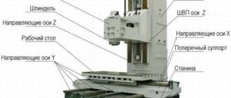
Kinematic diagram of a screw-cutting lathe 1k62
Kinematic diagram of a screw-cutting lathe
Basic parameters of gears, worms, screws and nuts of the headstock of a 1k62 lathe
| the name of detail | Drawing number | Number of teeth or starts | Module or pitch, mm | Material | Heat treatment |
| VI axis gear | 1К62-02-103 | 60 | 2 | Steel 40Х | HRC46…54 |
| V axis gear | 1К62-02-104 | 26 | 4 | Steel 40Х | HRC45…50 |
| Gear-coupling 1st axis | 1К62-02-105 | 56,51 | 2,25 | Steel 40Х | HRC48…52 |
| Gear-coupling 1st axis | 1К62-02-106 | 50 | 2,25 | Steel 40Х | HRC48…52 |
| Gear III axis | 1K62-02-107 | 47,55,38 | 2,25 | Steel 40Х | HRC46…54 |
| Gear III axis | 1К62-02-108 | 65 | 3 | Steel 40X | HRC46…54 |
| Gear III axis | 1K62-02-109 | 45 | 3 | Steel 40Х | HRC45…50 |
| Gear III axis | 1К62-02-110 | 22 | 2,5 | Steel 40Х | HRC45…50 |
| VI axis gear | 1K62-02-113 | 22;45 | 2,5;3 | Steel 40Х | HRC48…52 |
| Gear XII axis | 1К62-02-114 | 35,56,42 | 2 | Steel 40Х | HRC48…52 |
| V axis gear | 1K62-02-115 | 45 | 3 | Steel 40Х | HRC48…52 |
| V axis gear | 1K62-02-116 | 88 | 2,5 | Steel 40Х | HRC45…50 |
| VIII axis gear | 1K62-02-117 | 60;45 | 2;3 | Steel 40Х | HRC48…52 |
| Gear II axis | 1К62-02-118 | 39;34 | 2,25 | Steel 40Х | HRC50…54 |
| VIII axis gear | 1K62-02-119 | 35;28 | 2 | Steel 40Х | HRC48…52 |
| Gear XIII axis | 1K62-02-120 | 28 | 2 | Steel 40Х | HRC48…52 |
| VII axis gear | 1К62-02-121 | 24;36 | 2,25 | Steel 40Х | HRC45…50 |
| Gear II axis | 1K62-02-122 | 38 | 2,25 | Steel 40Х | HRC50…54 |
| Gear II axis | 1K62-02-123 | 29 | 2,25 | Steel 40Х | NRS46…54 |
| Gear II axis | 1K62-02-124 | 21 | 2,25 | Steel 40Х | HRC48…52 |
| VIII axis gear | 1К62-02-125 | 42 | 2 | Steel 40Х | HRC48…52 |
| Gear IV axis | 1К62-02-276 | 45 | 3 | Steel 40Х | HRC45…50 |
| Gear IV axis | 1К62-02-277 | 88 | 2,5 | Steel 40Х | HRC48…52 |
| VI axis gear | 1K62-02-1016 | 52; 43 | 4; 3 | Steel 40Х | HRC46…54 |
Bearing layout for screw-cutting lathe 1k62
Specification of rolling bearings for lathe 1k62
Main bearing dimensions:
- inner ring diameter (d)
- outer ring diameter (D)
- bearing width (B)
| No. position according to the diagram | Bearing designation | GOST | Bearing type | Overall dimensions d, D, B mm | Quantity per machine |
| 1 | 209 | 8338-57 | Single row radial ball bearing | 45, 85, 19 | 4 |
| 2 | 7000108 | 8338-57 | -«- | 40, 68, 9 | 2 |
| 3 | 208 | 8338-57 | -«- | 40, 80, 18 | 4 |
| 4 | 7604 | 333-71 | Single row tapered roller bearing | 20, 52, 22,5 | 1 |
| 5 | 7605 | 333-72 | -«- | 25, 62, 22,5 | 1 |
| 6 | 7509 | 333-72 | -«- | 45, 85, 25 | 1 |
| 7 | 7306 | 333-72 | -«- | 30, 72, 21 | 2 |
| 8 | 7308 | 333-72 | -«- | 40, 90, 25,5 | 1 |
| 9 | 7309 | 333-72 | -«- | 45, 100, 27,5 | 1 |
| 10 | 7206 | 333-72 | -«- | 30, 62, 17,5 | 1 |
| 11 | А3182120 | 7634-56 | Double row radial roller bearing with short cylindrical rollers | 100, 150, 37 | 1 |
| 12 | A46215 | 831-62 | Single row angular contact ball bearing | 75, 130, 25 | 2 |
| 13 | 206 | 8338-57 | Single row radial ball bearing | 30, 62, 16 | 4 |
| 14 | 204 | 8338-57 | -«- | 20, 47, 14 | 1 |
| 15 | 205 | 8338-57 | -«- | 25, 52, 15 | 6 |
| 16 | 7506 | 333-71 | Single row tapered roller bearing | 25, 52, 16,5 | 1 |
| 17 | 7000106 | 8338-57 | Single row radial ball bearing | 30, 55, 9 | 11 |
| 18 | 7204 | 333-71 | Single row tapered roller bearing | 20, 47, 15,5 | 5 |
| 19 | 7203 | 333-71 | -«- | 17, 40, 13,5 | 2 |
| 20 | В8206 | 6874-54 | Single thrust ball bearing | 30, 52, 16 | 1 |
| 21 | B8106 | 6874-54 | -«- | 30, 47, 11 | 1 |
| 22 | 203 | 8338-57 | Single row radial ball bearing | 17, 40, 12 | 4 |
| 23 | 7205 | 333-71 | Single row tapered roller bearing | 25, 52, 16,5 | 4 |
| 24 | 7000107 | 8338-57 | Single row radial ball bearing | 35, 62, 9 | 2 |
| 25 | 2007106 | 333-71 | Single row tapered roller bearing | 30, 55, 17,2 | 1 |
| 26 | 709 | 8338-57 | Single row radial ball bearing | 45, 75, 11 | 2 |
| 27 | 8107 | 6874-54 | Single thrust ball bearing | 35, 53, 12 | 1 |
| 28 | 8205 | 6874-54 | -«- | 25, 47, 15 | 1 |
Purpose and scope of application of a universal metal machine
Parts processed by universal screw-cutting lathes are mainly made of ferrous and non-ferrous metals.
Turning cones and threading are additional functions of the machine. If the kit includes additional tools and drills, then the functionality of the machine is even greater.
Since these machines have large dimensions and impressive weight, they can rarely be found in private workshops. Areas of application:
- production of small series of products;
- single production and processing of parts;
- in rare cases - mass production.
But on an industrial scale, screw-cutting lathes are rarely used.
Main design features
A universal screw-cutting lathe consists of main structural units, which are standard elements. These include:
- caliper;
- bed;
- thrust and spindle headstock;
- electrical equipment;
- drive shaft;
- guitar gears;
- a box that provides selection and change of feeds;
- lead screw - it is this detail that distinguishes a screw-cutting lathe from a standard lathe.
Depending on some features, the accuracy of the machine may vary. Therefore, universal equipment can be of both accuracy class N and increased – P.
Front and rear stock
The headstock or spindle has the main role of fixing the workpiece in processing and transmitting rotation to the workpiece from the electric motor.
Classification methods
Screw-cutting lathes are divided into several types. There are several most popular characteristics by which machines of this type are classified.
Weight
There are small machines that are convenient to use in a personal workshop or large ones that are intended for industrial production.
Large and heavy turning devices are mainly intended for use in mechanical engineering and energy. Heavy machines – over 40 tons in weight.
The lightest ones weigh no more than half a ton. Each type of mass has its own characteristics:
- Lungs. As a rule, the cross-sectional diameter in such equipment is no more than 500 mm.
- Machines weighing up to 15 tons are considered medium and they do not process parts with a diameter greater than 1250 mm.
- 15-400 tons. Rarely found with high accuracy rates. Typically this is Class H equipment.
Maximum part length
This parameter is determined by the distance between the centers of the machine. With equal diameters of manufactured products, there are machines capable of processing long and short workpieces.
Max diameter
According to the maximum diameter, there is the most extensive classification of parts. They start from 100 mm and go up to 4000 mm. In addition to the above indicators, a parameter such as productivity is often used for classification.
There are machines for small-scale production, for medium-scale production and for large industrial scales. The latter option is used on conveyor lines.
Main technical characteristics
A screw-cutting lathe has a number of technical characteristics that you should focus on when choosing a machine both for production and for a personal small workshop.
Number of revolutions
The number of revolutions may vary depending on the size and purpose of the lathe, but the maximum number of revolutions is 2000 rpm.
Larger speeds are for thin holes in small parts. For personal purposes in a small workshop, a machine that operates at a speed of 1000 rpm is sufficient.
Accuracy class
There are several classes of machine precision. For processing small parts and on an industrial scale, high-precision machines marked P are used.
For everyday use, machines with a normal level of accuracy, which are marked N, are sufficient. There are special classes of accuracy that are used only in very large industries. This is indicated by the letters B, C.
Repairing the headstock housing of a lathe
Restoring the holes for the spindle rolling bearings by boring and then pressing the bushings into the headstock housing is done in rare cases when there is significant wear on the holes, which cannot be compensated by appropriate adjustment of the bearings.
Provided that the spindle bearings are installed in special housings (machines) and flanges, the wear of the bearing holes is compensated by replacing the corresponding housings and flanges, followed by adjusting the internal diameter to the bearing and adjusting the radial runout (permissible deviation 0.01 mm).
When restoring holes by boring and installing compensation bushings, the headstock housing is repaired as follows.
Initially, use a scraper to clean the burrs on the supporting surfaces 8 and 10 (Fig. 59, o) of the headstock housing 3 and in the holes for bearings 1 and 4. Then the worn hole is bored (in our case, the hole of the front bearing 4) on a horizontal boring machine 6 for subsequent pressing of the bushing.
The headstock body is installed on the table 9 of a horizontal boring machine with supporting surfaces 8 and 10. The installation accuracy is verified using indicators 2 and 5 on the mandrel 7 fixed in the spindle of the boring machine (the spindle axis must be parallel to the supporting surfaces 8 and 10). The installation is aligned using the undeveloped surfaces of holes 1 and 4 (permissible deviation 0.05 mm along the length of the part, installation accuracy 0.01 mm).
After securing the headstock body of the lathe to table 9 of the horizontal boring machine, the worn hole is bored to press in the bushing, and the inner size of the bushing should be taken with an allowance for boring, and the outer diameter of the bushing should be equal to the inner diameter plus 15-16 mm (permissible deviations: radial runout - no more than 0.01 mm; non-parallelism of the hole axis to the supporting surfaces 8 and 10 of the headstock base - no more than 0.01 mm over a length of 300 mm).
After pressing in bushing 1 (Fig. 59, b), it is necessary to bore it and trim the end to press in the bearing (permissible deviation - radial runout - no more than 0.01 mm).
The headstock housing is installed on the repaired frame guides and the correct installation and scraping of the supporting surfaces 8 and 10 are verified (Fig. 59, a). Then, control mandrel 1 is inserted into the conical hole of the spindle (Fig. 59, c) and using indicator 3 installed on bridge 2, the parallelism of the spindle axis in the horizontal and vertical planes is checked, while the bridge with the indicator is moved along the frame guides along the length of the mandrel.
If there are deviations above the permissible ones, the defect is eliminated by scraping the base of the body (supporting surfaces) of the headstock.
Non-parallelism of the spindle axis is allowed: in the vertical plane, the free end of the mandrel can only be above the horizontal axis (0.02 mm over a length of 300 mm); in the horizontal plane - no more than 0.02 mm over a length of 300 mm, and the free end of the mandrel can only be deflected towards the cutter.
After scraping, the number of paint prints should be at least 10 on an area of 25 X 25 mm.
To repair the headstock guides, it is necessary to install the spindle in its supports (bearings). The headstock with the spindle is placed on the frame guides, aligned to the level, and a control mandrel is inserted into the conical hole of the spindle (Fig. 59, c). A stand with an indicator 3 is installed on the caliper carriage or on the universal bridge 2, the measuring pin of which is sequentially brought to the upper and side generatrices of the mandrel. Then, deviations from parallelism are determined when the carriage moves along the bed guides. The guides are scraped according to the paint prints, taking into account the deviations noted on the control mandrel. The number of paint prints must be at least 10 on an area of 25 X 25 mm. Non-parallelism in the vertical plane is allowed no more than 0.02 mm over a length of 300 mm. The free end of the mandrel can only be tilted upward. Non-parallelism in the horizontal plane is allowed no more than 0.01 mm over a length of 300 mm. The free end of the mandrel may deviate towards the cutter.
Application of CNC
Modern lathes, especially foreign ones, are numerically controlled. This allows for high processing accuracy.
The features of such machines are the following nuances:
- All moving parts of the machine are controlled by a mini control unit. The machine has a complex electrical circuit.
- All parameters of the CNC machine exactly comply with GOST and are also described in the equipment passport. Accuracy indicators, dimensions, and speed are indicated here.
- Machines of this kind can be used at home because they are small in size, but can withstand surprisingly high loads for their size.
- The equipment has an indication, as well as a display for entering information.
- Benchtop CNC machines are used for high-precision machining of small parts. At the same time, home production has a high profitability rate.
Overview and diagrams of common models
Among the diverse model range and several generations of machines that are produced by our production, there are several models that continue to be popular for their technical characteristics and universal properties.
All of them are used in production or in domestic conditions to this day. At the same time, they continue to be worthy competitors to foreign analogues.
These are reliable, durable and durable devices capable of performing a huge number of different functions.
1L532
One of the most popular machines in the former USSR, which can successfully process workpieces of medium and large sizes.
At one time, this equipment was successfully exported to many countries around the world. Accuracy class – N. Machine weight – 43 tons.
16U04P
High precision equipment. The largest diameter of the part processed above the bed is 200 mm. Machine weight – 750 kg.
1P611
A machine used in production, including for turning wheels of railway vehicles. According to GOST, they are distinguished by increased accuracy and have the ability to brake the spindle. Device weight 560 kg. Easily performs the following functions:
- Drilling.
- Segment.
- Cutting internal and external threads.
- Treatment of various surfaces.
The largest diameter of the workpiece above the bed is 250 mm.
1D601
This machine is better suited for purely domestic use. The accuracy is lower than the previous machine. It features high performance even after many years of operation.
Moving the caliper is only possible manually. The weight of the entire machine is about 30 kg. Due to the small dimensions, the maximum length of the workpiece to be processed is 18 cm.
16K40
One of the most popular models that has really gained popularity among craftsmen. Belongs to the middle class of equipment with accuracy class N.
Since 1932, several tens of thousands of various screw-cutting lathes have been produced in the USSR. They were used not only in production, but also for training young people, in schools, colleges, and many had desktop machines in garages, homes, and their own workshops.
Such equipment will help to bore a hole, level the required surface, or drill an existing hole. It is important, focusing on the initial specifications of the equipment, to purchase the most suitable model.
Assembling machine headstock components
The assembly of components during major and medium repairs of a machine has its own peculiarity. It lies in the fact that the restoration of the original dimensional chains, broken due to wear of a number of parts, is not carried out according to the drawing, but is often carried out on site. In this case, the repairman, unlike the assembler, has to determine the shapes and sizes of expansion joints for installation in the unit being repaired.
The headstock is assembled after it is fully equipped with all parts, including newly manufactured, repaired (restored) and those that are determined to be suitable for further use.
Parts received for assembly must be free of nicks and burrs and cleanly washed.
It is recommended to assemble in the following sequence: roller 4 (Fig. 62); shift handles 1 and 2 (“normal step”, “increased step”); rack 12; handle 14 switching search; gear shift knob 3; roller 7, 13, 9; clutch shaft 8; roller 6; spindle 5; shaft 11 (busting unit); roller 10 switching search; plunger pump with plate filter; oil pipes; headstock housing cover.
The most complex components of the headstock are clutch shaft 8 and spindle 5, the assembly of which is discussed below.
Clutch shaft assembly
Before installing the shaft assembly into the headstock housing of the machine, the parts are adjusted and assembled on a workbench as follows:
- Bushings are pressed into gears 5 and 8 (Fig. 63) of friction clutches. Drill holes and cut lubrication grooves in the bushings. Scrape the holes of the bushings along the ground journals of the shaft 11. The rotation of the gears on the shaft should be easy and smooth. Testing is done manually.
- Saw grooves in piston 1 and in shaft 11 along rocker arm 2. Drill out a hole for the axle assembled with the rocker arm. The movement of the rocker arm together with the piston should be easy, without jamming
- Friction discs 6 and 7 are adjusted along the shaft splines 11 and gear wheels 5 and 8. The surfaces of the walls of the shaft splines and gear grooves must be cleanly processed. (The notches formed on the walls of the grooves are removed by milling). The movement of the rings should be easy, without jamming
- Install ring 14 on the splines of shaft 11. A hole for the axle is drilled into the ring together with piston 1. The shaft groove is sawed through for free passage of the axle. The movement of the ring connected to the piston by an axis along the shaft axis should be easy, without jamming
- Assemble the clutch shaft assembly. Press ball bearing No. 307 onto shaft 11, install gear 8, a spring ring and a set of friction discs. Install ring 14 with screwed nuts 15, connect it to the piston 1 axis, mount the second set of friction discs on the shaft and lock it with a spring ring. Install gear 5, thrust ring, ball bearing No. 208, compensation ring and secure it to the shaft with ring 4. Rocker arm 2 is connected to shaft 11 with an axis and install coupling 3. Having previously adjusted the friction clutches with nuts 15, check inclusion by moving coupling 3, while each The arms of the rocker arm 2 should alternately enter the hole of the coupling 3. Then the corresponding clutch is secured to the shaft. The rotation of the friction clutches on the shaft should be easy and without jamming when the clutch 3 is located in the middle of the rocker arm 2.
- Mount the assembled unit in the headstock housing and secure it with flange 9. Shaft rotation should be easy, without jamming
- Install pulley 13 with the rear flange, ball bearings No. 213 and thrust and spacer rings on flange 9 and secure with a nut. Place flange 10 on the splined shank of shaft 11 and fasten it to the pulley with screws. Screw nut 12 onto the shaft and secure it with screws. The rotation of the pulley together with the shaft should be easy, without jamming
Assembling the spindle of a screw-cutting lathe
The assembly of the screw-cutting lathe spindle (Fig. 64) begins after making sure, after appropriate checks, that all spindle parts are in working order or repaired. It is also necessary to check the correct fit of the gears on the spindle and the condition of the spindle journals. A key 20 is installed in the groove of the spindle.
First, assemble the rear spindle support. In the glass 18, fastened to the headstock body with screws 17, a seal 15 and then an angular contact ball bearing 16 are installed; it is positioned so that the thinnest end of the outer ring of the bearing is directed towards seal 15. Then install the intermediate ring 10 and bearing 9, in which the thin end of the outer ring should face the opposite direction from the seal. The bearings are secured with a nut 19, which is locked with a screw 8.
For ease of assembly, spindle 2 is placed in a vertical position and roller bearing 3 and ring 5 are installed on it; then screw nut 6 until it comes into light contact with ring 5.
Next, the spindle is inserted into the housing 26 through a hole in its front wall, a double-rimmed gear 22 with a sleeve 24 secured by a spring 23 and a gear 21 are put on the spindle. After this, the end of the spindle is inserted into the rear support and the front support is inserted into the hole in the housing; at the same time, the outer ring 4 of the bearing is slightly shifted towards the housing.
Having installed rings 11 and 12 at the end of the spindle, screw nut 13 with a wrench until the spindle is in place, which is determined by the tightening force and the rotation of the spindle. First, the axial movement of the spindle is noticed as it rotates uniformly, then the axial movement of the spindle stops and its rotation becomes tight.
When installing the spindle, use a special bushing to move ring 4 so that it is located at the level of the inner ring of the bearing.
Having finished installing the unit, mount the gear 21 on the spindle and screw in the stopper 7. To prevent the possibility of self-unscrewing, insert a special spring ring into the groove of the gear and the slot of the stopper. Complete the assembly by attaching flange 1.
Now you can begin adjusting the spindle supports, which begins with the rear support. Having unscrewed nut 13 slightly, turn the spindle so that the inner rings of the ball bearings take their normal position (the spindle then begins to rotate easily); then screw in the locking screw 14.
The front support is adjusted by screwing in nut 6 with stopper 25. The inner ring 3 of the bearing then begins to slide onto the spindle cone and expands more and more, making the connection correct and reliable.
The spindle clearances are checked in accordance with the description in Chapter. I (see Fig. 6).
Spindle rotation should be smooth, without jamming.
When adjusting the spindle, you should pay attention to the alignment of the teeth of the spindle gears in width with the mating gears of other rollers. The position of the oil discharge groove of the spindle relative to flange 1 is also checked, which should be located as shown in Fig. 64. Otherwise, oil will be thrown out when the spindle is running.
The assembled headstock is checked for rotation by hand at all speeds. Jamming and knocking are not allowed. Switching the handles should be easy, with a force of up to 3 kg.
Table of contents
The gearbox of a lathe refers to the main parts of the spindle drive. It is created to transfer the energy of movement of the electric motor to the remaining parts of the mechanism. It is also used to change the spindle speed and, accordingly, the operating speed. Depending on the design of the machine, there can be two types of placement of this unit. The box can be built into the spindle head housing or mounted in a separate housing unit, which must still be connected to the spindle.
If the gearbox of a screw-cutting lathe is built-in, then this makes the design significantly simpler, this is especially noticeable in terms of installation. This greatly simplifies device management. At the same time, they create conditions for an increase in temperature during the working process, and also create additional vibrations. Thus, they are used only in normal precision models, since precision machines use the split-box operating principle.
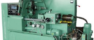
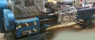
photo: lathe gearbox
The speed can be changed in a stepless or stepwise manner as well as reversing. Several methods are used for this, for example:
- Sliding blocks consisting of 2-3 wheels with straight teeth that move along a shaft with a guide key or splines. Used in medium-sized machines.
- Friction clutches with manual or electromagnetic activation. The use of chevron or helical gears is allowed here, so speeds can be changed on the fly. This system is used in medium and small sized automatic machines.
- Cam clutches that work in conjunction with chevron and helical gears. They have low switching conditions and small limits of movement. This system is well suited for heavy machines.
- Replaceable gears with relatively small axial dimensions. This system provides a wide range of spindle speeds. They are also used in operating and special automatic and semi-automatic machines, which are used in mass production.
- Continuously variable control mechanisms, or as they are also called, variators. They provide smooth speed control during machine operation. Used in medium and small machines.
The device of the headstock of a screw-cutting lathe
The headstock or spindle headstock of a screw-cutting lathe is a cast iron box, inside of which the gearbox - the spindle speed switching mechanism.
Technical characteristics, photographs and drawings are given on the page Screw-cutting lathe 1K62 .
The spindle is the main assembly of the headstock (spindle stock). The front end of the spindle has an internal conical bore with a No. 5 Morse taper, into which the front center and various fixtures for securing workpieces are inserted. At the front end of the spindle there is a landing cone along which chucks are installed to secure workpieces.
All gearbox shafts and the spindle rotate on rolling bearings, which are lubricated both by splashing (the gearbox is filled with oil) and by force, using a pump. The feed movement from the spindle is transmitted to the bit shaft and then to the feed mechanism.
Screw-cutting lathes have almost the same type of layout. The front spindle headstock is attached to the left end of the bed. It contains the machine's gearbox, the main part of which is the spindle. The movement is transmitted from the V-belt pulley. The interaction of gears is explained when describing the kinematic diagram. The spindle and all shafts are mounted on rolling bearings. The front spindle support contains a radial double-row roller bearing, in which preload is created by fitting the inner ring onto the tapered journal of the spindle. If you push the ring onto the cone with a nut, it expands and puts pressure on the rollers. The rear spindle support has two angular contact ball bearings that absorb radial and axial loads; The preload is adjusted with a nut tightening the inner rings. The gearbox shafts are mounted on tapered roller bearings, which is convenient for assembly and disassembly; Preload is adjusted using pressure screws. Since the shafts are long, they have a middle support.
On the left side of the friction clutch, which reverses the movement of the spindle, there is a large number of disks, since large torques are required in the forward direction of rotation. A special feature of gear blocks is the adhesive connections between the rims and the hubs. The wheel hub on the shaft is a band brake disc; The rod of the control mechanism, setting the clutch in the neutral position, turns on the brake (by pressing the roller). The wheel blocks are switched using flywheels and handles.
In some machines, the gearbox is located in the bed frame. In this case, it is connected to the spindle by a belt drive. Such machines are called split drive machines.
Kinematic diagram of a screw-cutting lathe
Headstock (gearbox) of a screw-cutting lathe
Headstock . In Fig. Figure 10 shows the headstock with gearbox. Rotation from the main electric motor is transmitted to a driven pulley sitting on shaft I. This shaft carries a reversible friction clutch, from which movement is transmitted to shaft II either through a block z = 56—z = 51, or through a wheel z = 50 and an intermediate block z = 24 -z = 36, sitting on a cantilever axle. From shaft II to shaft III, rotation is transmitted through a triple block z = 47—z = 55—z = 38. In the left position of the block z = 43—z = 52, sitting on the spindle, movement from shaft III is transmitted to the spindle directly through the wheels z = 65—z = 43, and in the right position of this block - through a buster installed on shafts IV and V. All shafts rotate on rolling bearings, which are lubricated both by splashing, since the gearbox is filled with oil, and by force - using a pump . The feed movement from spindle VI is transmitted to bit shaft VII and then to the feed mechanism.
Kinematic chain of cutting motion of a screw-cutting lathe
The mechanism for switching clutches in the spindle head of a screw-cutting lathe
Rice. 17. Mechanism for switching clutches in the spindle head of a 1k62 screw-cutting lathe
Clutch switching mechanism . Multi-disc clutches for enabling forward and reverse rotation of the spindle are controlled by handles 19 and 17 (Fig. 17, a). Handle 19 is used when setting up the machine, and during operation, handle 17 is used, which always moves along with the apron along the roller 18. The latter has a keyway d along its entire length and is connected to the handle 17 by a sliding key.
When the handle 17 is turned in the direction of arrows A and B, the roller 18 rotates, and with it the handle 19. The latter, through the rod 16, the rocker arm 15 and the roller 12, rotates the gear 11, which is meshed with the rack 10. A fork is attached to the left end of the rack 10 9, which with its annular sector enters the groove of the coupling 23. The movement of the coupling 23 along the hollow shaft 7 causes a slight rotation of the pawl 24, which, entering the transverse groove of the rod 8 with its lower protrusion b, causes the latter to move a small amount along its axis. The rod 8 is connected to the coupling 25 using a through pin 4, due to which the latter also receives small movements along the axis of the shaft 7.
When you move clutch 25 to the left, the spindle forward rotation clutch is activated, and when you move clutch 25 to the right, the spindle reverse rotation clutch is activated.
The friction clutches consist of disks 2 with external projections, with which they fit into the grooves a of the hubs of gears 1 and 6, and disks 26 with internal projections, with which they are connected to the splines of the hollow shaft 7. When the disks are compressed by the clutch 25, friction forces arise between them, which ensure the transmission of torque from shaft 7 to gear 1 or 6. To adjust the compression force of the disks both during assembly and as they wear out, threaded rings 3 and 5 are provided. To quickly stop the machine, use III installed on the roller (see also Fig. 16) band brake. Engaging the brake is associated with switching clutches. In the neutral position of the clutches, the rack 10 with its protrusion presses on the end of the double-arm lever 20, which tightens the tape 22 on the brake drum 21 and stops the machine drive. When one of the clutches is engaged, the protrusion of the rack 10 comes off the end of the lever 20 and the latter releases the band brake.
The machine model 1K62 is equipped with a time relay to automatically disconnect the electric motor from the network when the machine is idling for more than 3-8 minutes. For this purpose, a cam 14 is installed on the roller 12, which, when the clutches are in the neutral position, i.e., when the machine is idling, turns on a relay 13, pre-set for a certain (within 3-8 minutes) time. After this time, the relay turns off the power supply to the electric motor.
When the clutches are turned on, cam 14 moves to the side and the time relay is blocked.