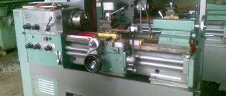
16K20F3 is a chuck-center lathe, its main purpose is turning parts such as rotating bodies in a closed semi-automatic cycle. The 16K20F3 lathe was made on the basis of the 16K20 screw-cutting lathe. It is also designed for processing parts with a curved or stepped profile in the axial section.
Specifications
Basic machine parameters
- With the largest processing diameter of the bed - 400 mm.
- With the largest caliper processing diameter - 220 mm.
- Distance between centers -1500 mm.
- Spindle bore - 51 mm.
- Spindle speed - 12.5-1600 rpm 24 steps.
- Power supply - 415 volts / 50 Hz / 3 phase.
- Heavy-duty screw-cutting lathe.
- Made in Russia.
- One-piece cast base.
- Pneumatic floating tail stock.
- Saddle lube.
- Metric configuration.
- Halogen work lamp.
- Reserve for mechanical protection of the cartridge.
- Protects the tailstock, lead screw and feed shaft.
- Cooling system.
Spindle
Acts as a hollow, multi-stage shaft made of steel, heat treated to increase durability.
The spindle has a steel structure and a longitudinal hole inside, it allows the workpiece to pass through. The spindle itself rotates thanks to specialized precision bearings. They are wear-resistant and precise in manufacture, and do not require frequent maintenance.
Caliper and feed
This is the part of the machine used to hold the tool and allows longitudinal and lateral movement of the tool.
This machine block is very rigid, which reduces the possibility of errors caused by elastic deformation of the sliding system during cutting.
Cutting slide
The slides are needed to adjust the thread engagement; they move in the longitudinal direction. The cutting head is attached to them.
Tailstock
Used to clamp a rotating cutting tool and as an additional support, used with rotating and non-rotating centers for hard cutting.
Electrical equipment
Thanks to electrical equipment, maximum protection of the worker is ensured, protecting him from electric shock. And the unit itself is protected from damage.
What does electrical equipment consist of:
- Main electric motor.
- An electric motor that moves the caliper and carriage.
- Electric pump with coolant system.
- Automatic shutdown systems.
- Fuses.
- Thermal relay.
- Grounding.
- Microswitch.
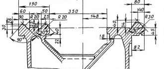
Tailstock of the machine 16K20F3S32
Drawing of the tailstock of the machine 16K20F3S32
The tailstock has a rigid structure. Using a handle, an eccentric shaft, a clamping bar and a lever system, the tailstock is secured to the frame.
If handle 13, retracted to the rearmost position, does not provide sufficient clamping of the tailstock to the frame, then it is necessary to set the required clamping force by adjusting screws 17 and 23 with lock nuts 13 and 24 released, changing the position of the clamping bar 19.
The quill is moved using an electromechanical head “PRIZ VS05” through a screw, in increments of 5 mm.
The constant clamping force of the part is ensured using disc springs.
Providing CNC complexes
The 16k20f3 machine without a numerical control system and a conveyor has dimensions of 3700x2210x1650 mm in length, width, and height, respectively. The weight of the installation is 4000 kg. The data is given for the delivery option without conveyor.
- SS-221-02R;
- Electronics NTs-31;
- Circuit 2PT-71;
- СС221-02Р Alcatel;
- N22-1M;
- EM-907.
The above list is quite short. To ensure that the consumer understands what kind of equipment is presented to his attention, separate labeling is provided. An index is added to the name 16k20f3, for example, C2 or C18. Using this parameter, specialists immediately determine which drive (Prize, Camron, Size) and CNC unit are installed in the system, and also evaluate the general capabilities of the equipment in terms of the list of operations performed.
Technical characteristics of the lathe 16K20
| Parameter name | 16K20 | 16K20P |
| Basic machine parameters | ||
| Accuracy class according to GOST 8-82 | N | P |
| The largest diameter of the workpiece installed above the bed, mm | 400 | 400 |
| Height of the center axis above the flat guides of the frame, mm | 215 | 215 |
| The largest diameter of the workpiece processed above the support, mm | 220 | 220 |
| Maximum length of the workpiece installed in the centers (RMC), mm | 710, 1000,1400, 2000 | 710, 1000 |
| The greatest distance from the axis of the centers to the edge of the tool holder, mm | 225 | 225 |
| The largest diameter of the drill when drilling steel parts, mm | 25 | 25 |
| Maximum mass of workpiece processed in centers, kg | 460..1300 | 460..1300 |
| Maximum mass of workpiece processed in the chuck, kg | 200 | 200 |
| Spindle | ||
| Spindle hole diameter, mm | 52 | 52 |
| The largest diameter of the rod passing through the hole in the spindle, mm | 50 | 50 |
| Spindle rotation speed in forward direction, rpm | 12,5..1600 | 12,5..1600 |
| Spindle rotation speed in reverse direction, rpm | 19..1900 | 19..1900 |
| Number of forward spindle speeds | 22 | 22 |
| Number of spindle reverse speeds | 11 | 11 |
| Spindle end according to GOST 12593-72 | 6K | 6K |
| Tapered spindle bore according to GOST 2847-67 | Morse 6 | Morse 6 |
| Spindle flange diameter, mm | 170 | 170 |
| Maximum torque on the spindle, Nm | 1000 | 1000 |
| Caliper. Submissions | ||
| Maximum length of longitudinal movement, mm | 645, 935, 1335, 1935 | 645, 935 |
| Maximum length of transverse movement, mm | 300 | 300 |
| Speed of fast longitudinal movements, mm/min | 3800 | 3800 |
| Speed of fast transverse movements, mm/min | 1900 | 1900 |
| Maximum permissible speed of movement when working on stops, mm/min | 250 | 250 |
| Minimum permissible speed of movement of the carriage (support), mm/min | 10 | 10 |
| Price for dividing the longitudinal movement dial, mm | 1 | 1 |
| Transverse movement dial division price, mm | 0,05 | 0,05 |
| Longitudinal feed range, mm/rev | 0,05..2,8 | 0,05..2,8 |
| Transverse feed range, mm/rev | 0,025..1,4 | 0,025..1,4 |
| Number of longitudinal feeds | 42 | 42 |
| Number of cross feeds | 42 | 42 |
| Number of threads to be cut - metric | ||
| Number of threads to be cut – modular | ||
| Number of threads cut - inch | ||
| Number of threads to be cut - pitch | ||
| Limits of metric thread pitches, mm | 0,5..112 | 0,5..112 |
| Limits of pitches of inch threads, threads/inch | 56..0,5 | 56..0,5 |
| Limits of modular thread pitches, module | 0,5..112 | 0,5..112 |
| Limits of pitch thread pitches, diametric pitch | 56..0,5 | 56..0,5 |
| The greatest force allowed by the feed mechanism on the cutter is longitudinal, N | 5884 | 5884 |
| The greatest force allowed by the feed mechanism on the cutter is transverse, N | 3530 | 3530 |
| Cutting slide | ||
| Maximum movement of the cutting slide, mm | 150 | 150 |
| Movement of the cutting slide by one division of the dial, mm | 0,05 | 0,05 |
| Maximum angle of rotation of the cutting slide, degrees | ±90° | ±90° |
| Scale division of the tool slide rotation scale, deg | 1° | 1° |
| The largest cross-section of the cutter holder, mm | 25 × 25 | 25 × 25 |
| Height from the supporting surface of the cutter to the axis of the centers (cutter height), mm | 25 | 25 |
| Number of cutters in the cutting head | 4 | 4 |
| Tailstock | ||
| Tailstock quill diameter, mm | ||
| Cone of the hole in the tailstock quill according to GOST 2847-67 | Morse 5 | Morse 5 |
| Maximum movement of the quill, mm | 150 | 150 |
| Movement of the quill by one division of the dial, mm | 0,1 | 0,1 |
| The amount of lateral displacement of the headstock body, mm | ±15 | ±15 |
| Electrical equipment | ||
| Main drive electric motor, kW | 11 | 11 |
| Electric motor for fast movement drive, kW | 0,12 | 0,12 |
| Coolant pump electric motor, kW | 0,125 | 0,125 |
| Dimensions and weight of the machine | ||
| Machine dimensions (length width height) RMC=1000, mm | 2795 × 1190 × 1500 | 2795 × 1190 × 1500 |
| Machine weight, kg | 3010 | 3010 |
Bibliography
Screw-cutting lathes 16k20, 16k20p, 16k20g, 16k25. Operating manual, NIIMASH, 1976
Acherkan N.S. Metal-cutting machines, Volume 1, 1965
Batov V.P. Lathes, 1978
Beletsky D.G. Handbook of a universal turner, 1987
Golovin G.M., Peshkov E.O. Special machines in instrument making, 1952
Denezhny P.M., Stiskin G.M., Thor I.E. Turning, 1972. (1k62)
Denezhny P.M., Stiskin G.M., Thor I.E. Turning, 1979. (16k20)
Lokteva S.E. Computer controlled machines, 1986
Modzelevsky A. A., et al. Lathes, 1973
Pekelis G.D., Gelberg B.T. Technology of repair of metal-cutting machines, 1970
Pikus M.Yu. A mechanic's guide to machine repair, 1987
Skhirtladze A.G., Novikov V.Yu. Technological equipment for machine-building industries, 1980
Tepinkichiev V.K. Metal cutting machines, 1973
Chernov N.N. Metal cutting machines, 1988
Home About the company News Articles Price list Contacts Reference information Download passport Interesting video KPO woodworking machines Manufacturers
Purpose, functionality
16K20 was produced by the Moscow Machine Tool Plant from 1971 to 1986. This is one of the most successful models of Soviet machine tool construction, which became the basis for many modifications, such as 16K25, 16K20M, 16K20M and more modern versions with CNC control - the 16K20FZ, 16A20F3, 16K20T1 machine.
This unit is capable of performing the following technical operations:
- turning;
- boring;
- trimming ends;
- drilling;
- deployment;
- countersinking;
- thread cutting (metric, modular, pitch, inch).
Among the operational advantages of this unit in comparison with analogues of that time, we highlight reliability, processing accuracy, ease of maintenance, endurance and high productivity.
General view of the machine 16K20
The universal machine 16K20 has the following characteristic features:
- rigid structure of the frame, which is box-shaped and stands on a base in the form of a monolithic slab; the frame is equipped with guides made of hardened steel;
- possibility of fixing workpieces in a chuck or in centers;
- reinforced design of the tool holder, ensuring the most reliable fixation of the working tool;
- spindle mounted on precision rolling bearings;
- equipped with a variety of restrictive and blocking mechanisms, due to which operational safety is achieved;
- the presence of scale rulers with sights, allowing the operator to set the cutting sled extremely accurately;
- equipped with a device for shutting off the caliper feed.
Soviet enterprises produced analogues of this model, the most common of which are: ZHA-805, MK6058, KA-280 and 16VT20. to menu
Specifications
Let's look at the main parameters of the 16K20 lathe:
- accuracy group (in accordance with GOST No. 8-82) - N;
- maximum processing diameters: above the bed - 400 mm, above the support - 220 mm;
- the height of the centers above the guides is 215 mm;
- length of processed parts when installed in centers: from 710 to 2000 mm;
- distance from centers to tool holder - up to 225 mm;
- weight of processed workpieces: in the center - up to 130 kg, in the chuck - up to 200 kg.
Parameters of spindle unit 16K20:
- hole diameter - 52 mm;
- rod diameter - 50 mm;
- spindle rotation speed - from 12 to 1600 rpm, in reverse - from 19 to 1900 rpm;
- number of spindle speeds: forward speed - 22, reverse speed - 11;
- spindle cone type - Morse 6K;
- spindle end type - 6K;
- spindle flange - Ø170;
- maximum torque - 1000 Nm.
Machine design 16K20
Feed options:
- length of movement: longitudinal - from 646 to 1935 mm, transverse - 300 mm;
- movement speed: longitudinal - 3800, transverse - 1900 mm/min;
- feed range: longitudinal - from 0.05 to 2.9, transverse - 0.025 to 1.4 mm/rev;
- number of serves in both directions - 42;
- maximum feed forces: longitudinal - 5584, transverse - 3530 N.
Cutting slide parameters:
- slide travel length - 150 mm;
- step moving by one division - 0.05 mm;
- rotation angle - up to 90 degrees;
- cross-section of the cutter retainer - 25*25 mm;
- number of cutters in one slide - 4 pcs.
Tailstock parameters:
- headstock cone type - Morse 5;
- maximum quill movement - 150 mm;
- the step of moving the headstock by 1 division of the dial is 0.1;
- The amount of displacement of the headstock in the transverse direction is 15 mm.
The machine is equipped with 3 electric motors: the main motor with a power of 11 kW, the coolant pump motor with a power of 0.125 kW and the spindle fast feed drive with a power of 0.12 kW. The dimensions of the 16K20 are 279*119*150 cm, the total weight of the unit is 3010 kg. to menu
data-ad-client=»ca-pub-8514915293567855″ data-ad-slot=»5929285318″>
This is interesting: Metal laser cutting technology - illuminating the essence
Full set price
Today, many businesses are selling off their equipment to install modern and innovative production lines. A fully equipped CNC lathe 16K20F3 can be purchased for a price starting from 300 thousand rubles. The market offers different prices, the average size is 500 thousand rubles. If you buy modernized models, then the cost will be from 800 - 1 million rubles.
To this day, the 16K20F3 CNC lathe is considered one of the most successful equipment models, on the basis of which domestic and foreign engineers have developed and are creating analogues that successfully operate in large and small-scale production of a variety of products with excellent quality characteristics.
In addition to the machine itself, you can buy various components and spare parts: the model is considered universal and many elements produced for other series of turning equipment are suitable for it.
Technical characteristics of the machine 16K20T1
| Parameter name | 16K20T1 | 16K20T1.01 | 16K20T1.02 |
| Basic machine parameters | |||
| CNC system type | NTs-31 | NTs-31 | NTs-31 |
| The largest diameter of the workpiece above the bed, mm | 500 | 500 | 500 |
| The largest diameter of the workpiece above the support, mm | 215 | 215 | 220 |
| Maximum length of the workpiece, mm | 1000 | 1000 | 1000 |
| Maximum processing length, mm | 900 | 900 | 905 |
| The largest diameter of the processed rod, mm | 53 | 53 | 53 |
| Spindle | |||
| Main movement motor power, kW | 11 | 11 | 11 |
| Number of spindle speeds | 24 | 22 | b/s |
| Spindle hole diameter, mm | 55 | 55 | 55 |
| Spindle speed limits, rpm | 10,0…2000 | 12,5…2000 | 22,4…2240 |
| Number of automatically switched speeds | 2 | 9 | b/s |
| Spindle speed range, manually set, rpm | Row I – 10..1000Row II – 20..2000 | Row I – 12.5..200Row II – 50..800Row III – 125..2000 | Row I – 22.4..355 Row II – 63..900 Row III – 160..2240 |
| Headstock spindle center according to GOST 13214-67 | 7032 – 0043 Morse No. 6 | 7032 – 0043 Morse No. 6 | 7032 – 0043 Morse No. 6 |
| Tailstock quill center according to GOST 13214-67 | 7032 – 0045 Morse No. 5 | 7032 – 0045 Morse No. 5 | 7032 – 0045 Morse No. 5 |
| Spindle end according to GOST 12593-72 | 6K | 6K | 6K |
| Maximum torque on the spindle, Nm | 1000 | 1000 | 1000 |
| Maximum drilling diameter for steel/cast iron, mm | 25/ 28 | 25/ 28 | 25/ 28 |
| Submissions | |||
| Maximum movement of the caliper longitudinal / transverse, mm | 900/ 250 | 900/ 250 | 905/ 275 |
| Maximum speed of longitudinal/transverse working feed, m/min | 2,0/ 1,0 | 2,0/ 1,0 | 2,0/ 1,0 |
| Limits of pitches of cut threads, mm | 0,01..40,959 | 0,01..40,959 | |
| Range of longitudinal feed speeds, mm/min | 0,01..2,8 | 0,01..2,8 | 0,01..20,47 |
| Transverse feed speed range, mm/min | 0,005..1,4 | 0,005..1,4 | 0,005..10,23 |
| Speed of fast longitudinal/transverse strokes, m/min | 6/ 5 | 6/ 5 | 7,5/ 5 |
| Discretion of longitudinal/transverse movement | 0,01/ 0,005 | 0,01/ 0,005 | 0,01/ 0,005 |
| Number of positions on the rotary toolholder (number of tools in the turret) | 6 | 6 | 6 |
| OSU system parameters | |||
| OSU system designation | NTs-31 | NTs-31 | NTs-31 |
| Number of coordinates | 2 | 2 | 2 |
| Number of simultaneously controlled coordinates | 2 | 2 | 2 |
| Resolution in the longitudinal direction (discreteness of the task along the Z axis), mm | 0,01 | 0,01 | 0,01 |
| Resolution in the transverse direction (discreteness of the task along the X axis), mm | 0,005 | 0,005 | |
| Feedback sensor type | BE-178 | BE-178 | BE-178 |
| Threading sensor type | BE-178 | BE-178 | BE-178 |
| Electrical equipment. Drive unit | |||
| Number of electric motors on the machine | 5 | 6 | 7 |
| Main motion drive electric motor, kW | 11 | 11 | 11 |
| Electric motor for longitudinal feed drive, kW | 2,2 | 2,2 | 2,2 |
| Cross feed drive electric motor, kW | 1,1 | 1,1 | 1,1 |
| Turret head electric motor, kW | – | 0,18 | 0,37 |
| Electric motor of the carriage lubrication station, kW | 0,12 | 0,12 | 0,18 |
| Electric motor of the spindle head lubrication station, kW | – | – | 0,27 |
| Cooling pump electric motor, kW | 0,12 | 0,12 | 0,18 |
| Total power of electric motors, kW | 14,54 | 14,72 | 16 |
| Total power of the machine, kW | 24 | 24 | 25 |
| Dimensions and weight of the machine | 3175 x 1700 x 1700 | 3175 x 1700 x 1700 | 3230 x 1700 x 1700 |
| Weight of CNC machine, kg | 3800 | 4100 | 3800 |
Bibliography:
A software lathe with an operational control system 16K20T1. Operating manual 16K20T1.000.000 RE
Grachev L.N. Design and adjustment of computer-controlled machines and robotic complexes, 1986, p. 17
Acherkan N.S. Metal-cutting machines, Volume 1, 1965
Batov V.P. Lathes., 1978
Beletsky D.G. Handbook of a universal turner, 1987
Denezhny P.M., Stiskin G.M., Thor I.E. Turning, 1972. (1k62)
Denezhny P.M., Stiskin G.M., Thor I.E. Turning, 1979. (16k20)
Modzelevsky A. A., Muschinkin A. A., Kedrov S. S., Sobol A. M., Zavgorodniy Yu. P., Lathes, 1973
Pikus M.Yu. A mechanic's guide to machine repair, 1987
Skhirtladze A.G., Novikov V.Yu. Technological equipment for machine-building industries, 1980
Tepinkichiev V.K. Metal cutting machines, 1973
Chernov N.N. Metal cutting machines, 1988
Home About the company News Articles Price list Contacts Reference information Download passport Interesting video KPO woodworking machines Manufacturers
CNC
When using numerical software, workpiece processing operations are performed using preset programs. They make it possible to correct information supplied from the operator console, as well as use external memory cassettes. The final data is displayed on a special display, after analysis of which a decision can be made on setting up the subsequent process.
Automation of the process is accompanied by 6, 8 or 12 positions, allowing you to change the processing diameter or the horizontal rotation axis. The working head is equipped with a disk on which three axial and six radial elements can be mounted. In addition, it can be used with 8-12 blocks for various tools.
To increase the efficiency of the 16K20F3 machine, the technical characteristics and description of which are given above, can be further modernized by changing the kinematic diagram or installing a modern energy-saving design. The CNC complex significantly expands the functionality of the unit in question. Thanks to it, the accuracy and speed of processing parts, as well as the finishing mode, are improved. CNC machines have a range of longitudinal and transverse movements - 0.005 and 0.01 millimeters, respectively.
Process control and automation programs
The delivery package of the 16k20fz CNC machine includes many ready-made scripts for carrying out certain operations in automatic mode. The programmer's task, when using standard programs, includes minimal modifications designed to regulate the size of the workpiece and certain parameters of the final product.
However, the documentation for the control system includes detailed instructions that describe the syntax used in programming and an available list of standard commands. It is also declared:
- codeword order, which is the recommended order of addresses in one code frame;
- syntax format in a single frame;
- required final commands and frame header format.
In addition to describing the available structure of an individual frame, the documentation provides data regarding the processing discreteness adopted in the system. In particular, the maximum allowed number of symbols for a code word is given, as well as the maximum commands within one frame.
Some numerical control systems come with their own automated command development systems. Such tools greatly facilitate the operator’s work. Their tasks include:
- automatic verification of program syntax compliance with the code used;
- monitoring compliance of the listing with the set of restrictions adopted in the system;
- support for help, provision of information given in the documentation for the machine.
Development tools allow you to typify individual programmer actions, use existing schemes for processing certain surfaces, and reduce the redundancy of commands. As a result of the use of such products, the productivity of personnel, the machine, and the work process as a whole increases significantly, while the level of failures and the number of incorrect instructions decreases.
Kinematic scheme
The drawing in the figure depicts the mechanical connections between the key components and clearly shows their interactions. Conventional symbols are generally accepted. Under the callout next to the asterisk the number of worm passes is indicated, and above it the number of gear teeth.
Tailstock of lathe 16k20
In the conical hole of the tailstock quill, stationary and rotating centers can be installed to support the rear end of the workpieces, as well as an axial tool for processing the central holes.
The tailstock moves along the frame guides manually and is secured in the required position by turning the handle. The quill moves when the handwheel rotates and is secured in the required position by turning the handle.
Rotary tool holder of the machine 16K20F3S32
Drawing of the rotary tool holder of the machine 16K20F3S32
The design of the rotary tool holder is shown in Fig. 2.15. On the output shaft 4 there is a removable tool head (not shown in the figure), connected to the movable coupling half 6 of the flat-toothed coupling. The rotation of the tool holder is carried out through a worm pair 1–2, a cam coupling half 7, the other half 8 of which is rigidly connected to the shaft 4. At the initial moment of movement of this cam coupling, the shaft 4 is fed to the left, while the movable coupling half 6 of the flat-gear coupling moves away from the stationary coupling half 3 and the tool holder begins turning to the desired position, which is determined by pressing the cam 10 on the corresponding limit switch 9. Then the engine is reversed and the coupling half 7 rotates in the other direction, while the coupling half 6 with the tool head is kept from turning by a lock. The cams of the coupling half 7 rest against the cams of the coupling half 8, the spring 5 is compressed and the coupling half 6 is fixed on the teeth of the coupling half 3. The clamping limit switch gives a command, the rotation motor is turned off, and the processing cycle begins.
In the removable tool head, you can install six cutter inserts or three tool blocks, which are adjusted to size outside the machine in special optical devices with adjusting screws in two planes.
The diagram shows a variant of a mechanized tailstock, in which the quill moves from the electromechanical head of the EG.
Brief history of the series
Two years later, in 1934, production of such models as the DIP-300, DIP-400, DIP-500 lathe was launched.
By 1937, special types of nomenclature and sizes were being developed. A unified system of symbols is adopted. Thus, the first machine produced by the plant was named 1D62, but the abbreviation DIP-20 was retained.
The year 1940 was marked by the creation of the 162K 26A machine, as one of the versions of the DIP-200.
Then various modernized machines were produced, and in 1948, the legendary 1A62 appeared. The models were produced in large quantities.
And finally, in 1971, the first prototype of the 16 to 20 machine was manufactured. The machine even received a gold medal at the fair in ’72.
From 1972 to 1973, reconstruction was carried out at the plant, this is due to the large-scale production of new 16K20 models. The company is developing mass production of this model, and at the end of 1973, the monthly production turnover reaches 1 thousand copies. About 10% of the total is exported.
Then various modifications of the 16 to 20 model appeared, including 16 K 25, 16 K2 0M, 16 K2 0P, 16 K 20V, 16 K 20G, 16 K 20K, 16K20F1, 16K20PF1, 16K20VF1 and others. All were based on the basic standards of the 16 to 20 model.
History of the creation of the machine
The first manual ancestor of automatic equipment was invented in 1932 at the Moscow plant. During the period from 40 to 50 years of the last century, many design bureaus around the world discussed and made attempts to develop automatic process control. Such research was also carried out in the USSR, which resulted in various modifications of the first model.
Over the many years of its existence, the design has repeatedly shown itself from the best side, and became the basis for the development of new, technically advanced machines, which took the place of the first serial model. The production of the 16K20F3 CNC lathe was stopped in the late 80s of the last century, but the equipment still copes well with its production tasks.
Features of design and functionality
Appearance
This machine is designed for various types of turning of workpieces. The diameter limit is 40 cm for external turning. When internal turning, the length of the workpiece should not exceed 100 cm.
The main advantage is the ability to install various types of CNC – closed, open and STS. For this purpose, the design provides contact connectors. The number of controlled coordinates when performing shaping is limited to two.
Additionally, the presence of automatic control allows you to perform the following operations on the 16K20F3 lathe, specified in the passport:
- automatic control over the feed value;
- changing the number of spindle revolutions;
- the ability to form threads according to the drawn up program.
To these qualities it is worth adding high precision of the work performed and good performance characteristics. According to the GOST 8-82 classification, the 16K20F3 machine has an accuracy rating of “P”. To adapt to the specific type of operations performed, turning equipment of this type can be equipped with additional modules and an expanded range of settings.
This is interesting: Turret lathes - design, operating principle
Advantages and disadvantages of the machine
Thanks to its unified design, the 16K20F3 CNC lathe will allow you to solve even the most complex production operations. Experts call the main advantage of the machine the ability to carry out modernization using various CNC controls. The process of changing programming is quite simple.
In addition to the above properties, the 16K20F3 CNC lathe has several more advantages:
- level of productivity, thanks to which it is possible to produce a large volume of products per shift;
- there is no need for preliminary testing and manual adjustments;
- the accuracy of parts processing is one of the best;
- the speed of operation corresponds to modern standards of operation of such equipment;
- this model has a minimum number of workpiece reinstallations;
- the design is distinguished by the reliability and strength of all components;
- the dimensions and weight of the 16K20F3 CNC lathe allow for the installation of heavy parts;
- affordable price.
Widespread production of the model has long ceased, but the machine can still be purchased: even in used condition, the equipment works efficiently and productively. Many shops offer to purchase various brands and series of turning mechanisms.
If we talk about significant shortcomings of the equipment, then there are none: the 16K20F3 CNC lathe, when used correctly and when replacing worn parts is observed, guarantees a long service life and excellent quality of the products produced. Now you can use modernization services to turn an old device into an innovative and functional machine.
Operator's manual for screw-cutting lathe 16К20Ф3 with CNC 2Р22
This manual contains information for the operator on servicing the 16K20F3 machine with a 2P22 or 2P22.01 CNC system. Contents of the operator's manual:
- Purpose of the program
- Program execution conditions
- Program Execution
- Operating procedure
- General provisions
- Linking the device to machine parameters
- Linking the reference system to the machine
- Linking a tool to a reference system
- Linking a reference system to a part
- Semi-automatic input of the initial position and exit of the tool to this position
- Input mode
- Program output
- “Manual control” mode
- Automatic mode
- Test mode
- Coding system and frame order
- Programming chamfers, arcs and fillets
- Programming canned cycles
- Drawing up programs when entering from punched tape
- Messages to the operator
- Device exchange signals
- Algorithms for the operation of electrical automation of a controlled machine
Operator's manual for screw-cutting lathe 16K20RF3S32 with CNC 2P22
This manual contains information for the operator on servicing the 16K20RF3S32 machine with a 2P22 or 2P22.01 CNC system. Contents of the operator's manual:
- Purpose of the program
- Program execution conditions
- Program Execution
- Operating procedure
- General provisions
- Linking the device to machine parameters
- Linking the reference system to the machine
- Linking a tool to a reference system
- Linking a reference system to a part
- Semi-automatic input of the initial position and exit of the tool to this position
- Input mode
- Program output
- “Manual control” mode
- Automatic mode
- Test mode
- Coding system and frame order
- Programming chamfers, arcs and fillets
- Programming canned cycles
- Drawing up programs when entering from punched tape
- Messages to the operator
- Device exchange signals
- Algorithms for the operation of electrical automation of a controlled machine
Location of the components of the TS16k20f3 machine
Location of the main components of the TS16k20f3 machine
Location of the main components of the TS16k20f3 machine
Location of the main components of the TS16k20f3 machine
List of main components of the TS16k20f3 machine
- Cabinet;
- Bed;
- Caliper;
- Headstock;
- Longitudinal feed drive;
- Cross feed drive;
- Cabinet;
- Cabinet with electrical equipment;
- Turret;
- Control panel with CNC system;
- Centralized pulse lubrication system;
- Coolant supply and collection system;
- Rear grandma.
Lathe 16A20F3
The 16A20F machine is designed for turning external (diameter up to 400 mm) and internal surfaces of parts (length up to 1000 mm) with a stepped and curved profile in the axial section in a closed semi-automatic cycle.
The 16A20F3 lathe is designed on the basis of the 16K20F3 screw-cutting lathe, so the layout, components and movements of these machines are the same. The design of the machines has been largely unified.
The CNC device of the machine (the machine can be equipped with various types of CNC systems: open, closed, CNC) provides shaping movement (the number of simultaneously controlled coordinates is two), changing feed values, switching spindle speeds, indexing the cutting head and threading according to the program.
Machine tools can be produced with various CNC devices, designed for integration into flexible production modules (GPM), as well as in special and specialized versions when equipped with adjustments in agreement with the customer.
16A20F3 machines can be equipped with removable tool heads with 6, 8 and 12 position tool holders with a horizontal axis of rotation.
Design Features:
- high-strength bed
made of cast iron grade SCh20 with heat-treated ground guides ensure long service life and increased processing accuracy - main motion drive
including 11 kW main motor and spindle head provides the highest torque of up to 800 Nm - high-precision spindle
with a bore of 55 mm (optional 64 mm), allowing the processing of parts made of bar material; the processing zone can be equipped with both a linear adjustment and a turret - reliable protection of ball screw pairs
ensures durability of the movement mechanisms along the X and Z coordinates; the machine is equipped with CNC systems and electric drives, both domestically produced and manufactured by foreign companies
Main movement mechanism of the machine
The machine is equipped with a 16A20F3.025 spindle head. having three ranges with a ratio of 1.25:1; 1:2; 1:5.8; manually switchable.
The machine spindle is mounted in double-row and single-row conical bearings. Bearings are adjusted at the machine manufacturer's factory and do not require adjustment during operation.
The position of the spindle head axis on the frame is adjusted using two screws. The spindle head is lubricated from a lubrication station mounted on the base of the machine. To ensure the possibility of threading, a threading sensor is installed on the spindle head.
A frequency-controlled asynchronous electric motor with a control range with a constant power of 1500...4500 rpm (1000...3500 with DC motors made in Bulgaria) is used as the main movement drive.
The transmission of rotation from the electric motor to the first shaft of the spindle head is carried out by a 2240L20 poly V-belt with a gear ratio of 115:257 (160:257 in the case of using a DC electric motor manufactured by NRB).
The base of the machine is a rigid casting. The base, the electric motor of the main movement, lubrication stations for the guides of the carriage and the spindle head are installed on the base. Two types of bases are used:
- with a window for chip collection and an opening for installing a chip removal conveyor, which is inserted from the right side;
- without a window, divided vertically in the middle part by a solid partition, in this case the middle part of the base serves as a collector for chips and coolant, the compartment in the lower right part of the base serves as a coolant reservoir, and a coolant pump is installed at the rear on the right side of the base.
| The largest diameter of the product installed above the frame, mm | 500 |
| The largest diameter of the workpiece above the bed, mm | 320 |
| The largest diameter of the workpiece above the support, mm | 200 |
| Maximum length of the installed product in centers, mm | 900 |
| Diameter of cylindrical hole in spindle, mm | 55 |
| Maximum transverse travel of the caliper, mm | 210 |
| Maximum longitudinal stroke of the caliper, mm | 905 |
| Number of controlled coordinates | 2 |
| Number of simultaneously controlled coordinates | 2 |
| Spindle speed range, min-1 | 20…2500 |
| Maximum speed of fast movements - longitudinal, mm/min - transverse, mm/min | 7500 4000 |
| Number of tool head positions | 8 |
| Main drive drive power, kW | 11 |
| Total power consumption, kW | 13 |
| Overall dimensions of the machine, mm | 3700x2260x1650 |
| Machine weight, kg | 4050 |
Front spindle head of machine 16K20F3S32
Drawing of the front spindle head of the machine 16K20F3S32
Installation of the headstock with the spindle axis along the calculated line of the machine centers on the bed is done with two screws.
The headstock lubrication is centralized from a special lubrication station mounted on the base of the machine.
The spindle is mounted in two tapered roller bearings of the Gamay type or domestic No. 3182120 class. "C" and No. 46216 class. "A".
The selection of the radial clearance in the rear bearing and compensation of thermal deformations is carried out under the action of springs 21.
Attention! The Gamay bearing is adjusted at the machine manufacturer's factory and does not require adjustment during operation of the machine.
In machines 16K20FZS5 and 16K20FZS8, a threading sensor I is installed in the headstock.
To constantly sample the backlash in the gearing, gear 6 is constantly pressed by springs 2. The resolution of the sensor is 1000 pulses per revolution and I is zero pulse for the position of the spindle when inserting into the thread when cutting threads in several passes.
Spindle head lubrication is centralized.
Design and principle of operation
The structural diagram of the 16k20f3 lathe shows familiar components, functional elements and a classic layout. The device consists of:
- grounds;
- the main system of rigidity of the working area organs, represented by the bed;
- mobile support carriage;
- spindle type headstocks;
- hydraulic system, which has its own electric motor;
- guides;
- gearboxes (for automatic speed control modes);
- electromagnetic couplings;
- spindle head gears for manually changing rotation speed ranges;
- tailstock;
- a wheel that drives a worm gear that displaces the caliper carriage;
- tool holder with a rotating holder secured with screws.
The lubrication system provides for automatic start when the main drive of the machine starts operating. In the design of the device, the developers have provided a safety relay circuit. The operation of the machine is blocked when problems are detected in various functional units, when the load is exceeded, or when protective covers are opened.
The classical design of the system imposes some restrictions on the size of the processed workpieces. Thus, the maximum diameter of the part located above the bed is 400 mm. When working with a workpiece above a support, the size is limited to 220 mm. The maximum length of the part is 1 m.
The operating principle of the equipment is also quite clear and familiar. The workpiece is positioned, fixed in the spindle, then the required types of cutters are installed and program execution is initiated. To achieve optimal load parameters and processing speed, the operator can adjust the speed and other parameters of the system.