10/25/2021 Author: VT-METALL
From this material you will learn:
- Welding arc definition
- Key features of the welding arc
- Areas of application of the welding arc
- Nature and structure of the welding arc
- Types of welding arcs
- Welding arc power sources
- Criteria affecting the power of the welding arc
- Current-voltage characteristics of the welding arc
- Welding arc combustion conditions
In modern realities, industry cannot do without welding. And it, in turn, is based on such a phenomenon as the welding arc, which advanced scientists worked on in their time. Thanks to it, high strength is created, which is so necessary in the process of joining metal products, transforming them into one whole. However, when performing this procedure, certain nuances are important, such as, for example, a properly selected power source and combustion conditions, otherwise the seam may turn out crooked.
Next, we will talk in detail about the nature and structure of the welding arc, in what areas it is used, what types it is and how it is used correctly. With this information, any welder will instantly deepen his knowledge and strengthen his position among specialists in this field.
What is a welding arc and its definition
A welding arc is a long-lasting electric discharge between electrodes with a potential difference that occurs in a gaseous environment. Due to the high density of electric current, the metal through which it flows quickly heats up - first to the plasticity temperature and then to the melting temperature. The maximum temperature theoretically achievable in an electric arc is up to 7000 °C. In practice, it allows you to melt metals with a melting point above 3000 °C, including tungsten.
From the point of view of electrical circuit theory, an electric arc is a conductor consisting of ionized gas. When current flows through it, a large amount of thermal energy is released.
There are several types of electric discharge:
- Smoldering. Low-energy discharge with a relatively weak current at reduced gas pressure, used in fluorescent lamps and plasma screens.
- Spark. It is excited at normal pressure and has an intermittent shape. Such discharges include lightning and an ignition spark in a car engine.
- Arc. Continuous discharge at normal pressure. Used for electric welding, for arc lamps.
- Crown. Excited on a heterogeneous surface between areas with different potentials.
Corona discharge is used to purify gases from dust contaminants.
Structure and temperature characteristics of the welding electric arc
It is quite possible to bring the temperature of a metal workpiece to the melting point in a very short period of time, but according to the laws of physics, this requires the formation of a powerful electric arc. Its main operating characteristics are:
- voltage – voltage value displayed in volts;
- amperage – electric current strength, the value of which is presented in amperes;
- level of flux density of corpuscles/charge carrier particles.
From an electrical engineering point of view, an arc column is a conductor between opposite poles (meaning positive and negative).
It is materialized through a gaseous medium. Features of the pillar are a high resistance value, the ability to produce sparks and glow. Carrying out a thorough analysis of the structure of the electric arc will reveal how temperature affects the metal. In general, its length is relatively small - it fluctuates around the 5 centimeter mark. The structure of the electric arc includes 3 areas:
- the pillar itself. This is the luminous segment visible to the human eye;
- anodic region – approximately 10 µm;
- cathode region – about 1 µm.
The temperature of the welding electric arc is determined by the flow of free electrons formed at the cathode. The heating level of the cathode itself reaches 38 percent of the temperature of the resulting plasma. Electrons - particles with a negative charge - move in a gaseous medium towards the anode, and elements carrying a positive charge move towards the cathode. In general, the following picture is observed: the pillar is neutral throughout its entire existence.
Inside the column, the temperature of the particles can reach 10,000°C. When they come into contact with metal, they heat it up to 2350°C. The point where electrons penetrate is called the anode spot by physicists. Compared to another spot, called the cathode, its temperature indicator is 6 percent higher. Plasma emits waves in the infrared, visible and UV ranges. But this radiation can harm human skin and organs of vision. Therefore, welders are required to work in special protective equipment for safety reasons.
Nature and structure
When an arc is ignited, an electrical circuit is created. It involves two electrodes - the anode and the cathode, as well as a section of ionized gas. Flowing through a gas cloud, an electric current causes it to heat up and produce an intense glow associated with the emission of photons.
According to the sections of the circuit, the structure of the welding arc includes three main areas:
- anode - 10-4 cm thick;
- cathode 10-5 cm;
- arc column, 4-6 mm long.
In the first two zones, active spots appear; the maximum voltage drop and maximum heating occur in them.
The voltage drop in the welding column itself is small.
When exposed to an electric arc, in addition to elevated temperature, there is another important factor - very intense ultraviolet radiation. It has a harmful effect on the human body, primarily on the organs of vision and skin.
Welding arc structure
To avoid harm to health when working with electric welding, it is necessary to use personal protective equipment: a welding mask, gloves and thick clothing and shoes made of non-flammable materials.
Brief description and history of invention
What arc is called a welding arc? This is a substance that carries the power of an electrical discharge flowing among the vapors of melting metal and additives. It has individual characteristics:
- formation is characterized by large heat releases - the temperature reaches 6 thousand degrees;
- this produces a powerful luminous flux, so the welder needs special equipment to protect the face and organs of vision, thick clothing and gloves;
- it is an excellent conductor of high current current, and therefore poses a danger to humans;
- the best way to reliably connect metal structures of varying complexity.
The primacy in who invented it and in the primary description of the physical phenomenon is still debated among pundits - the British chemist, physicist and geologist Sir Humphry Davy , who described the electric discharge arc in 1808, is officially considered the discoverer. The Russian scientist-inventor, professor of physics from the Medical-Surgical Academy of St. Petersburg V.V. Petrov discovered a similar phenomenon and described it in detail 6 years earlier than the Englishman.
Varieties
There are several classifications of arcs according to various criteria.
According to the electrical connection diagram, electric welding arcs are divided into:
- Direct action. One electrode is the structure to be welded, the other electrode is consumable. The circuit is formed by the electrode and the metal of the parts being welded. An arc is ignited in the gap between them.
- Indirect action. The discharge is ignited between two parallel infusible electrodes and brought to the workpieces to be welded.
Classification of the welding arc according to the electrical connection diagram
According to the type of gas medium in which the discharge is excited, they are divided into:
- Open. Works in the air. The working area is surrounded by a cloud of evaporated metal, combustion products of the electrode coating.
- Closed. The discharge occurs under a layer of flux powder; the cloud consists of evaporated particles of metals and inert gases released when the flux powder melts.
- With forced injection of inert gases. A mixture of inert gases with carbon dioxide and hydrogen in certain proportions is blown into the working area under low pressure. The purpose of such injection is to protect the material of the weld pool and the workpiece zone heated to the plasticity temperature from contact with oxygen and nitrogen in the air.
By duration of work:
- constant (for long-term work);
- pulse (powerful single pulse, used for contact welding).
According to the design and purpose of the electrodes used:
- Infusible (graphite, tungsten). Such electrodes are not consumed during the welding process; the weld material is formed from the molten metal of the workpieces.
- Fusible. Made from steel alloys. During the process, the metal rod of the electrode melts, flows into the weld gap and, together with the melted edges of the workpieces, forms a suture material.
Classification of the welding arc according to the electrodes used
The composition of fusible electrodes includes special alloying additives that increase the strength and durability of the resulting compound.
Quenching in switching equipment
The development of switching equipment and the variety of methods for its implementation provided the impetus for the study of arc extinguishing methods. Let's take a closer look at them.
By increasing its resistance
The method consists of successively increasing the resistance, which helps to reduce the current . Once a certain limit is reached, the current will no longer be able to support the discharge, after which it will go out.
The main disadvantage is the long extinguishing time, which is accompanied by heat and energy losses.
Zero current method
Modern AC circuit breakers are designed to use this method. According to the laws of physics, the current passes through zero at the end of each half-cycle. During the transition, the arc is briefly extinguished. At the same time, the area between the contacts is saturated with charged elements, which reduce the dielectric properties of the gas.
The essence of the method is to sharply increase the dielectric properties of the gas by deionizing the medium.
Methods for deionizing the medium between contacts
Deionization is one of the main reasons for discharge termination. There are several ways to activate this process:
- Increasing the gap between contacts.
- Increasing the pressure of particles in the contact medium.
- Cooling of the contact medium.
- Blast wave effect.
In the latter type of switches, sulfur hexafluoride is used as an extinguishing agent, which acts under high pressure on the space between the contacts. As a result, low-mobility ions are formed that are unable to support arc combustion.
Combustion conditions
Under normal conditions, at normal pressure and temperature of 20 ° C, gases, and above all air, are not conductors. In order for them to conduct electricity, special conditions must be created: a large number of ions must be released from atomic orbits. This process is called ionization.
The work required to release one electron is called the ionization potential. For various materials it ranges from 3.5 to 20 electron volts. The lowest potential is typical for alkaline elements: potassium, calcium and their compounds. These substances are added to the electrode coating or welding wire in order to maintain stable discharge parameters. They are also added to the composition of flux powder for closed type welding.
To ensure high quality welded joints, it is necessary to maintain stable electric arc parameters, such as current, voltage, and temperature.
Temperature is determined by the following factors:
- Cathode material.
- Cathode dimensions.
- Environmental conditions.
Arc temperature distribution
The constancy of the current parameters - voltage and strength - is ensured by the current source. A large number of designs of such sources have been developed for welding work - from outdated bulky welding transformers and rectifiers to modern inverters and semi-automatic machines.
About arc welding modes
The joining of parts by fusion is carried out under various conditions. A set of measures, indicators and parameters designed to ensure good quality of the weld in any situation is called the welding mode.
The parameters characterizing it are divided into 2 groups:
- basic;
- additional.
The first include:
- electrode diameter;
- current strength;
- arc voltage.
The joining of parts by fusion is carried out under various conditions.
Extra options:
- position of the seam in space;
- speed of work;
- composition and thickness of the metal.
The current strength is determined by the properties of the welding machine and is indicated in the instructions for it. The amount of heat generated, and therefore the depth of penetration, depends on it. Thick-walled elements of large metal structures exposed to heavy loads are connected with increased current. On the contrary, it can burn through a thin part, so the amperage is reduced.
The diameter of the electrode must correspond to the current strength.
Otherwise, the following negative points arise:
- Reduced diameter. The coating on the rod is damaged and the arc becomes unstable.
- Oversized diameter. The current density decreases, the length of the arc and its position become unstable, the seam becomes uneven and fragile.
Parameters of manual welding modes are given in the table:
| Thickness of welded parts, mm | 0,5 | 1-2 | 3 | 4-5 | 6-8 | 9-12 | 13-15 | 16 |
| Electrode diameter, mm | 1 | 1,5-2 | 3 | 3-4 | 4 | 4-5 | 5 | 6-8 |
| Current strength, A | 10-20 | 30-45 | 65-100 | 100-160 | 120-200 | 150-200 | 160-250 | 200-350 |
Regardless of the thickness of the workpieces, seams on vertical surfaces and ceilings are made with an electrode with a diameter of 4 mm.
Powerful connections are made in several approaches:
- Boil the root of the seam using a rod with a diameter of 3-4 mm.
- Apply the required amount of surfacing using thicker products.
Powerful connections are made in several approaches.
As the speed of the process increases, the width of the seam decreases, and vice versa. This parameter should be kept within reasonable limits. If the speed is too high, the metal does not have time to completely melt, and uncooked areas form in the joint. When welding slowly, the steel spreads, which also negatively affects the quality of the seam.
The width of the connection and the depth of penetration depend on the trajectory of the electrode. It is moved in a straight line, zigzag, herringbone, etc.
Emergence
An electric arc occurs, or, as welders say, “ignites” when the electrode is briefly short-circuited to the workpiece. The flowing current heats up the metal and it begins to melt. The gas surrounding the contact site also becomes very hot, and this energy becomes sufficient for its ionization.
After the electrode and the part are disconnected, the gas column between them is ionized and becomes capable of conducting an electric current, which rushes through it and the welding arc begins to burn.
If you do not remove the electrode, current flows through the contact point, no arc occurs, and the electrode, as welders say, “sticks.” To ignite the arc, it will have to be torn off from the workpiece and touched briefly again.
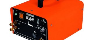
Inverter for welding work
Let us briefly note that the difference between an inverter and other welding machines is as follows:
- Consumes half as much electricity.
- The current parameters allow rapid arc formation.
- Combustion stability during welding.
- This is a complex design that can vary the current intensity for maximum arc stability.
- It converts alternating current into direct current, but at a higher frequency and vice versa.
- The product has a built-in step-down transformer.
The last phase consists of directing high frequency direct current to the rectifier and then to the electrode.
How is the power of a welding arc determined?
The power of the arc determines the productivity of welding work and the thickness of the workpieces being joined. The power itself depends on the following factors:
- Welding arc length. Determines the amount of heat released during combustion. With a longer length, the power increases, and vice versa.
- Current strength. Higher current allows a longer arc to not go out.
- Voltage. In a small range, an increase in voltage also leads to an increase in power.
Increasing voltage is rarely used, in specific, highly professional cases. In ordinary conditions, they operate with current strength.
Harm and the fight against it
The physical parameters of the discharge can pose a threat to both human health and equipment. High-voltage networks carry a particularly high risk of occurrence - the length of such a discharge can reach one and a half meters.
Important! The burning of an arc is accompanied by the release of a huge amount of heat. The average temperature can reach 2500-3000 Cº.
But even in everyday life, when you unplug the power cord of a powerful electric heater, you can see a small flash that formed when the contact was interrupted.
As a means of protecting contacts, special arc-extinguishing chambers are used - a housing made of dielectric material with a set of several conductive partitions. They take on the discharge, dividing it into several parts, which helps to cool it.
The structure of a vacuum circuit breaker.
The operation of high-voltage networks involves the use of various types of switches:
- oil;
- vacuum;
- gas;
Discharge duration
In practical applications, continuous discharge mode is more often used. However, pulse mode is also common. It is used for contact welding.
Welding of workpieces is not carried out in a continuous seam, but at several points. Such a connection does not provide tightness, but is strong enough to make thin-walled structures, such as housings for household appliances, various devices and installations, and car bodies.
The process is carried out by a non-consumable massive electrode, which is pressed against the workpiece with great force. A short-term current of very high strength is passed through the electrode - up to several thousand amperes. At the point of contact, the metal of both workpieces melts, and at the end of the pulse it cools and crystallizes as a single whole.
Next, the electrode (or workpiece) moves along the seam line to a new point, is pressed against it and a new impulse is applied.
Roller electrodes for resistance welding
There is a variation of this method that allows you to obtain tight connections. In this case, the electrode is made in the form of a roller rolling along the surface of the workpiece. The pulses are supplied at short intervals; the guiding zones along the rolling line partially overlap and form a continuous weld material. This technology is used for automatic welding of pipelines.
Arc welding
The source of heat in arc welding is an electric arc that burns between the electrode and the workpiece. Depending on the material and number of electrodes, as well as the method of including the electrodes and the workpiece in the electric current circuit, the following arc welding methods are distinguished:
- according to the electrodes used - an arc with a consumable and non-consumable electrode;
- according to the degree of compression of the arc - free and compressed arc;
- according to the welding current supply diagram - an arc of direct and indirect action;
- by type of current - DC and AC arc;
- according to the polarity of the current - an arc on the direct polarity and an arc on the reverse side of the polarity;
- by type of statistical current-voltage characteristic - an arc with a falling, rising or hard characteristic;
- according to the method of protecting the weld - in a protective gas environment or under a layer of flux.
A welding arc is called
a stable, long-term discharge of electric current in a gaseous environment between energized solid or liquid conductors (electrodes) or between the electrode and the product.
The welding arc exists at currents from tenths of an ampere to hundreds of amperes. The arc is characterized by a high current density in an electrically conductive gas channel, the release of a large amount of thermal energy and a strong light effect.
The discharge is a concentrated source of heat and is used to melt metal during welding. An arc discharge of current occurs in an ionized atmosphere of gases and metal vapors. Ionization of the arc gap occurs during arc ignition and is continuously maintained during its combustion.
Electrical charges in a welding arc are carried by positively and negatively charged particles. Negative charges are carried by electrons, and positive and negative charges are carried by ions. The process by which positive and negative ions are formed in a gas is called ionization, and the gas is called ionized.
Gases, including air, do not conduct electric current under normal conditions. This is explained by the fact that under normal conditions, i.e.
at normal atmospheric pressure and air temperature 20 °C, the air environment consists of neutral molecules and atoms that are not charge carriers.
These molecules and atoms will become electrically conductive if they contain electrons, which arise when they are exposed to electric current.
For gases to conduct electrically, they must be ionized.
Ionization of a molecule (atom) is the removal of one or more electrons and the transformation of the molecule (atom) into a positive ion. If molecules (atoms) add electrons to themselves, negative ions appear.
Gas ionization is caused by external influences:
- sufficient increase in temperature;
- exposure to various radiations;
- the action of cosmic rays;
- bombardment of gas molecules (atoms) with fast electrons or ions.
The reverse process of ionization, in which electrons attach to a positive ion to form a neutral molecule (atom), is called recombination.
At ordinary temperatures, ionization can be caused by imparting high speeds to the electrons and ions already present in the gas using an electric field. Possessing high energy, these particles can break neutral atoms and molecules into ions. In addition, ionization can be caused by exposure to light, ultraviolet, x-rays, and radioactive radiation.
However, from a practical point of view and for safety purposes, other ionization methods are used.
Since metals have a large concentration of free electrons, these electrons can be extracted from the volume of the metal. There are several ways to extract electrons from a metal.
For electric arc welding, two methods are important:
- thermionic emission, in which free electrons “evaporate” from the surface of the metal due to high temperature. The higher the temperature, the greater the number of free electrons acquires energy sufficient to overcome the potential barrier in the surface layer and exit the metal.
- auto-electronic emissions. In field emission, electrons are extracted from a metal using an external electric field. An externally applied electric field changes the potential barrier at the metal surface and facilitates the release of electrons that have high energy and can overcome this barrier.
Ionization caused in a certain volume of a gaseous medium is usually called volume ionization. Volume ionization obtained by heating a gas to very high temperatures is called thermal ionization.
At high gas temperatures, a significant portion of the molecules have sufficient energy so that neutral molecules can be broken into ions during collisions. In addition, as temperature increases, the total number of collisions between molecules increases. At very high temperatures, radiation from the electrodes and radiation from the gas play a significant role in the ionization process.
The passage of electric current through gases is called an electrical discharge.
An arc discharge is a type of electrical discharge.
There are other types of electrical discharge in gases:
- short-term spark discharge, which occurs when the power of the power source is insufficient to maintain a stable arc discharge;
- corona discharge, which occurs in non-uniform electric fields and manifests itself in the form of a glow of ionized gas;
- a glow discharge that occurs at low gas pressures (for example, in gas-light tubes).
For welding metals, a direct electric arc is mainly used, i.e. an arc discharge is used between the product and the electrode. In such an arc, one electrode is a metal or carbon rod, and the second is the workpiece being welded.
Power is supplied to the electrodes - electric current. The current is generated by a special device - a power source. Power supplies produce alternating or direct current. Several regions are distinguished in the arc.
- cathode;
- cathode region;
- arc pillar;
- anode region;
- anode.
The distribution of electric potential along the length of the arc is uneven.
Near the electrodes, there are jumps in the potential drop caused by the conditions of the passage of electric current at the boundary between the ionized gas and the metal electrodes.
The arc discharge owes its existence to processes at the cathode. The cathode is the “supplier” of electrons. The reasons for the release of electrons are the existence of thermionic and field emission mentioned above.
Electrons emitted from the cathode are accelerated by the electric field. At the outer boundary of the cathode, electrons collide with molecules and atoms of gas located in the interelectrode space. In elastic collisions, when electrons enter molecules, the temperature of the gas increases. In inelastic collisions, electrons, transferring energy to particles, produce ionization of the gas.
As a result of intense thermal ionization, the arc column is an ionized gas consisting of electrons and ions - plasma. Under the influence of an applied electric field, electrons move towards the anode, and positively charged ions move towards the cathode.
As a result of intense bombardment of the electrode surfaces with ions and electrons, the metal is instantly heated.
In this case, 43–43% of the total input power is released at the anode, 36–38% is released at the cathode, 20–21% of the power is lost to the environment through radiation and convection of vapors and gases, and the remaining power losses are due to splashing and waste of the metal being welded. When welding, as a rule, the anode is the part being welded.
When welding with a carbon electrode, the temperature in the cathode region reaches 3200 °C, in the anodic region 3900 °C. When welding with a metal electrode, the temperature of the cathode region is 2400 °C, and the anodic region is 2600 °C. In the arc column the temperature reaches 6000–7000 °C.
Different temperatures of the anode and cathode regions are used to solve technological problems. For example, when welding thin sheet metals, the cathode is the part itself, and the anode is the electrode.
Ignition (excitation) and burning of an electric arc
The process of igniting an electric arc can be divided into three stages
- short circuit of the electrode to the workpiece;
- withdrawal of the electrode to a distance of 3–6 mm;
- occurrence of a stable arc discharge.
A short circuit is performed to heat the end of electrode 1 and workpiece 2 in the area of contact with the electrode. After the electrode is removed from its heated end (cathode) under the influence of an electric field, thermoelectric emission of electrons 3 begins.
The collision of electrons rapidly moving towards the anode with molecules of gases and metal vapors leads to their ionization 4.
As the arc column heats up and the kinetic energy of atoms and molecules increases, additional ionization occurs due to their collision. As a result, the arc gap becomes electrically conductive and electricity discharge begins through it.
The arc ignition process ends with the occurrence of a stable arc discharge 6 with the appearance of a cathode region 5 and an anode region.
It is possible to ignite an arc without a short circuit and remove the electrode using a high-frequency electric discharge through the arc gap, which ensures its initial ionization. To do this, a source of high-frequency high-voltage alternating current (oscillator) is connected to the welding circuit for a short time.
Depending on the length of the arc discharge, there are:
- a short arc if its length is 2–4 mm;
- a normal arch if its length is 4–6 mm;
- a long arc, with a length of more than 6 mm.
The optimal welding mode is ensured with a short arc. With a long arc, the welding process proceeds unevenly, with unstable combustion and spattering of metal. The metal, passing through the arc gap, is more oxidized and nitrided.
Experts recommend determining the length of the arc by the sound it makes when burning. A normal-length arc produces a less loud and uniform sound. A long arc produces an uneven and crackling, louder sound, which is easily determined experimentally.
There are technological conditions for arc combustion, such as ignition, sensitivity to changes in length within certain limits, rapid re-ignition after a break and the necessary penetration of the metal.
Conditions for ignition of an electric arc:
- the presence of an electric arc power source of sufficient power to quickly heat the cathode to a high temperature when the arc is excited;
- the presence of ionization of the arc column (elements with a low ionization potential are introduced into the electrode or oscillators are used to excite the arc);
- stabilization of the combustion of the arc column (for example, introducing a choke into the power circuit). The dependence of the arc voltage on the current in the welding circuit is called the static current-voltage characteristic of the arc.
The current-voltage characteristic of the arc has three areas (Fig. 5):
- falling region I (at currents up to 100 A);
- hard region II (at currents of 100–1000 A);
- increasing region III (at currents above 1000 A).
The voltage required to initiate an arc depends on the type of current (alternating or direct), the arc gap, the material of the electrode and its coating, and the metal being welded.
An arc with a falling characteristic (I) is unstable and has limited use, since it requires inclusion of an oscillator in the welding circuit.
Materials and equipment for electric arc welding:
- welding arc power source;
- welding and power cables, electrode holder;
- welder's accessories - special suit, mask with protective glass;
- welding table or devices for assembling and fixing parts;
- measuring and marking tools;
- tools for cleaning seams and removing slag crust;
- fire-fighting equipment.
Advantages of electric arc welding:
- high technological effectiveness of the process;
- possibility of automation and mechanization of welding processes;
- smaller heat affected zone compared to gas welding;
- ease of regulation of the welding process;
- cheap consumables (electrodes);
- high speed of joining parts.
Disadvantages of electric arc welding:
- the need to use special welding transformers or inverters (converters);
- energy dependence (requires an electrical network or generators);
- preparing parts for assembly (cutting edges, fixing elements).
Temperature zones
Regardless of which electrode is used - fusible or infusible - the highest temperature is observed in the center of the arc column - up to 7000 ° C.
Zones of low temperature of the welding arc are located in the areas of the anode and cathode spots, but up to two-thirds of the total energy is released in them. These are centers of radiation in the infrared part of the spectrum.
The zone of maximum temperature is a source of radiation in the ultraviolet spectrum, which is the most harmful to human health.
When using alternating current for welding work, the concept of polarity loses its meaning. The anode and cathode change places 50 or 60 times per second.
Submerged arc welding
When working with alternating current, very simple equipment is used and there is less risk of the electrode “sticking”.
However, the stability of the arc in such welding sources is very dependent on the stability of the power supply. Their operation also causes voltage surges in the electrical network.
With alternating current
A variable energy source has less arc stability. This is due to a change in voltage polarity - when crossing zero, the arc discharge dies out. Thus, during one half-cycle the arc burns about 70% of the time. In manufacturing plants, the frequency of alternating current is 50 Hz. This means that 100 combustion interruptions occur in one second. They are accompanied by heat loss, which negatively affects the degree of ionization.
To stabilize the discharges, devices with an increased level of open circuit voltage are used.
Volt-ampere characteristics
The graph expressing how voltage depends on changes in current is called the current-voltage characteristic of the arc.
Under conditions of a constant column length and a gradual increase in current, the graph is divided into three main zones. In the first, called “downward,” the voltage decreases slightly as the current increases. This zone corresponds to the processes occurring during manual welding. In the second, as the current increases, the voltage remains stable. This part of the characteristic is used for semi-automatic welding using mechanical feed of welding wire.
And finally, the third region, called the “rising” region, is used in automatic welding, in which the voltage increases with increasing current.
Consumable electrode arc welding
During manual welding, the initial values on the curve correspond to the idle mode of the source. When the welder ignites the arc, the voltage decreases until a stabilization zone is reached, and this voltage is maintained throughout the entire operation.
For direct and reverse polarity
DC welding can be performed in 1 of 2 ways:
- “Plus” is connected to the workpiece, i.e. it becomes the anode. This polarity is called straight.
- A minus is connected to the workpiece, so that it becomes the cathode. This is reverse polarity.
DC welding can be done in a variety of ways.
When welding with a refractory electrode, the anode spot is hotter than the cathode spot, so the first method is used to join parts of medium or large thickness. Strong heating ensures deep penetration and, as a result, high strength of the seam.
Reverse polarity connection is used to connect thin-walled workpieces. Otherwise they will burn out.
When welding with a consumable electrode, the anode spot is colder, so they do the opposite.
Peculiarities
When compared with other types of electric discharges, the electric arc demonstrates the following differences from them:
- The high current density (up to thousands of A/cm2) makes it possible to develop high temperatures (up to several 1000 °C).
- Uneven voltage drop along the discharge column. In the anodic and cathodic zones it is very high, along the entire length of the column it is negligible.
- The temperature developed in the discharge zone is inversely proportional to its thickness.
- Multivariate operating modes when using different sections of the current-voltage characteristic.
Today, the welding arc is the fastest, most reliable and affordable method of creating permanent connections of metal parts and structures.
Electric welding has become the most common connection method. It is used in a variety of sectors of human life, construction, industry and transport.
TIG welding
To obtain high-quality, strong and durable seams, it is necessary to accurately select operating modes that determine the basic properties of the arc discharge. Modern welding equipment allows you to automatically maintain these parameters, making the operator’s work easier.
Power supplies (devices)
To create an arc, alternating, direct and pulsed current devices are used.
Alternating current is created by single-phase and three-phase transformers. Single-phase requires 220 volts, three-phase 380 volts (used in industry).
For direct current, welding inverters, rectifiers and autonomous units are used.
The most modern are inverter power supplies. Due to transistor control, inverters optimize the welding process by adjusting the current-voltage characteristic. You can find out what types of welding machines are used for manual welding from our article by clicking on the link.
Multi-station rectifiers are used in production and most often have a rigid current-voltage characteristic.
Application area
The welding arc is used in manual electric arc welding, which has become a reliable assistant for professionals and home craftsmen. Manual welding uses fusible electrodes coated with a flux compound. During the welding process, the rod material melts, forming the weld material, and the coating, when burned, releases a cloud of gases that protect the weld pool from exposure to oxygen. Manual welding is used both when working with conventional unalloyed structural steels and in unique welding operations on stainless, high-alloy alloys and non-ferrous metals.
The same arc is used in semi-automatic installations. Instead of an electrode, they use a welding wire fed by a mechanical device at a constant speed. Inert gases are pumped into the working area through the burner nozzle. This technology is characterized by optimal consumption of welding materials and high stability of weld parameters. Due to the high cost of the equipment, it is cost-effective for large volumes of welding work.
Automatic welding is carried out in special hermetically sealed volumes filled with inert gas. It is used for welding work with non-ferrous metals and especially critical operations with stainless alloys.
Kinds
- direct impact, burns steadily between the parts being connected and the electrode;
- indirect action - it is created by two electrodes, and the structure intended to be connected together is not involved in the general circuit;
- three-phase option - one phase is connected to each participant in the process;
- plasma - the column is compressed by protective gases.
To create an arc when using a transformer, you need to touch the workpieces being connected with an electrode, but modern equipment for welding allows you to activate the arc using a non-contact method; an oscillator is used for this.


