To facilitate the task of welding work with parts made of non-ferrous metals and stainless steel, it is necessary to use a welding oscillator. This useful device, which solves the problem of igniting the welding arc and maintaining it in a stable state, can be used equally successfully in production and at home.
Welding oscillator brand VSD-02, used to stabilize the arc
Why do you need a homemade oscillator?
The oscillator as a generating device is capable of operating on direct and alternating current. The purpose of the device is to excite the welding arc without contact of the electrode with the welding object and stabilize combustion. The type of electrode: tungsten torch tip or standard coated tip does not matter. The effect is achieved by transforming the mains current into high-voltage frequency pulses, with the following parameters:
- Mains voltage 220 V - output voltage - 2.5–3 thousand V;
- Current frequency 50 Hz - output frequency - 15–30 thousand Hz;
- Oscillator power – 250–400 W.
Electrical circuit of the oscillator
The operating principle of a homemade oscillator included in the welding device circuit with a degree of simplification:
- Supplying mains voltage to the welding device;
- The voltage passes through the windings of the step-up transformer and begins to charge the capacitor of the oscillating circuit;
- The storage capacitor accumulates the high-frequency high-voltage discharge voltage;
- In parallel, the system control unit opens the gas valve;
- The control unit releases a pulse when the capacitor capacity is filled onto the spark gap, a breakdown occurs;
- The oscillatory circuit is short-circuited, and resonant damped oscillations occur that go to the welding arc;
- When a capacitor breaks down, the fuse opens the electrical circuit;
- When the voltage drops, the next discharge is formed;
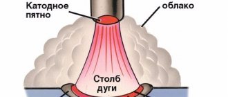
- The arc flashes in a gas cloud 3–5 mm above the part;
- When the remote contact breaks, the control circuit duplicates the arc ignition pulse.
Functional diagram of the oscillator
Interaction with the inverter
The principle of operation of the equipment that stabilizes the operation of the inverter is to additionally supply high voltage to the electrode. It arrives periodically, along with the main output voltage of the welding unit itself. The voltage comes in the form of pulses with characteristic amplitude modulation. Their parameters can reach 6 kV, and the frequency is in the range of 150-500 kHz.
The duration of the generated pulses is insignificant, so they have a very low duty cycle, quite sufficient to obtain the required power - up to 300 W. Their impact leads to the formation of a short-term electrical breakdown between the part and the electrode, increasing the reliability of the contact. The oscillator starts when the electrode approaches the metal by approximately 5 mm. Under the influence of electrical impulses, the air gap is ionized, after which an instantaneous discharge occurs.
DIY welding oscillator - components
There are a lot of schematic diagrams of oscillators for a welding device on the Internet. Both types are presented: serial and parallel connections. Lots of arguments in favor of each. Assembling the oscillator is half the battle. Difficulties await during setup and operation.
The device consists of several blocks. The oscillatory circuit as a spark generator of damped oscillations consists of 2 elements: a capacitor and a moving winding of a high-frequency transformer - an inductor.
DIY oscillator device
The step-up transformer of the device is assembled on the basis of a step-down transformer from 220 to 36 V, with a U-shaped core. To create a long magnetic line, 50% of the iron package is removed. The winding of the first core is wound like a welding one - we get a falling characteristic.
The step-up winding of the second core is designed to produce 1000 V. The lack of turns will force the spark gap to be constantly wound. Increasing the number of turns will lead to improved arc ignition in the spark gap. Overwinding leads to increased overheating of the coil.
Chokes 2 pcs. in a parallel circuit, 1 per transformer.
Manufacturing a spark gap from thickened, erosion-resistant WR-3 tungsten rods on copper rods requires the use of an adjustment mechanism. The optimum gap on the feeler gauge is 0.08 mm. Requires filling with a fast-hardening dielectric. To simplify things, spark plugs and air ionizers are used.
The output transformer is connected by a feedback line to the current sensor.
The blocking capacitor allows only high frequency current to pass through. The low-frequency current of the welding machine is blocked, which prevents the oscillator from short-circuiting.
Safety
To understand what an oscillator is and what it is needed for, you need to have minimal welding skills. The main differences between the devices under consideration and the principle of their operation are given above. When working with such devices, certain safety precautions must be observed.
It is necessary to constantly monitor the correct connection to the welding circuit and check the contacts for serviceability. In addition, you should work using a protective cover, which must be removed and put on when the device is unplugged. It is also necessary to periodically check the condition of the surface of the spark gap (clean it from carbon deposits with sandpaper).
Selecting the type of welding oscillator
Do-it-yourself oscillator for welding
Having decided to assemble a welding oscillator with our own hands, we will decide on the connection circuit. Serial or parallel connection, type of device operation: pulse discharge or continuous operation of the device.
Continuous devices are connected in parallel and in series. Most of these oscillators have a rectifier installed. The sequential circuit prevails - high voltage will not affect the welder.
Benefits of serial connection: one transformer is enough. The primary winding is supplemented with a pair of smoothing capacitors and a fuse. Secondary – with a spark gap and an oscillating circuit.
The pulse device is used on AC welding machines. The polarity change initiates the next arc ignition due to the synchronization of the sequence of actions:
- Activating the charger;
- Accumulation of charge by a capacitor;
- De-energization of the arc when passing the zero pole reversal mark;
- Discharging a capacitor with energy supplied to the arc gap.
Cyclic polarity welding devices are recommended for welding aluminum alloys. Stainless steels and non-ferrous metals are welded primarily at direct current.
Diagnostics of a homemade inverter and its preparation for operation
Making an inverter welding machine is half the battle
An equally important task is to prepare it for work, during which the correct functioning of all elements is checked, as well as their settings
The first thing you need to do when checking a homemade welding inverter is to apply a voltage of 15 V to the PWM controller and one of the cooling fans. This will allow you to simultaneously check the functionality of the controller and avoid overheating during such a test.
Checking the output voltage with a tester
After the capacitors of the device are charged, a relay is connected to the electrical supply, which is responsible for closing the resistor. If you apply voltage directly to the resistor, bypassing the relay, an explosion may occur. After the relay operates, which should happen within 2-10 seconds after applying voltage to the PWM controller, you need to check whether the resistor has shorted.
When the relays of the electronic circuit operate, rectangular pulses should be generated on the PWM board and supplied to the optocouplers. This can be checked using an oscilloscope. The correct assembly of the diode bridge of the device also needs to be checked; for this, a voltage of 15 V is applied to it (the current should not exceed 100 mA).
The transformer phases may have been incorrectly connected when assembling the device, which can lead to incorrect operation of the inverter and the generation of strong noise. To prevent this from happening, the correct phase connection must be checked using a dual-beam oscilloscope. One beam of the device is connected to the primary winding, the second to the secondary. The phases of the pulses, if the windings are connected correctly, should be the same.
Using an oscilloscope to diagnose an inverter
The correct manufacturing and connection of the transformer is checked using an oscilloscope and connecting electrical devices with different resistances to the diode bridge. Based on the noise of the transformer and the readings of the oscilloscope, they conclude that it is necessary to improve the electronic circuit of the homemade inverter apparatus.
To check how long you can continuously work on a homemade inverter, you need to start testing it from 10 seconds. If the device’s radiators do not heat up during operation for such a duration, you can increase the period to 20 seconds. If such a time period does not negatively affect the condition of the inverter, you can increase the operating time of the welding machine to 1 minute.
Let's prevent errors when making an oscillator
Detailed instructions for making an oscillator yourself
When following a reliable diagram step by step and high-quality assembly, effective retention of the arc does not occur. The reason is network congestion. Instead of the declared 220 V, it reaches 190–200 V. An autotransformer will solve the problem.
Throttle savings. From the spark gap there is a series of damped HF oscillations exceeding a kilovolt. The secondary winding without a choke will receive up to 50 V between turns. The turn takes on the appearance of a short-circuited one. The network power will be used for heating.
In order not to burn the entire welding device, we will take care of installing the choke. In addition to insulating spacers during winding, we impregnate the turns with bakelite varnish.
Current frequency within 150–300 kHz is safe. If the welder's body is considered as a conductor, the surface effect of the HF current does not affect the internal organs. But who wants to get a skin burn? We work only with reliable grounding. The shock at 10 kHz is quite sensitive.
Talk to experts about whether your design meets safety standards. Experts will evaluate the circuit design for the penetration of LF current into the electrode. They will warn you if the oscillator assembly is unsafe.
It is mandatory to include a blocking capacitor in the oscillatory circuit unit.
Operating rules
Using oscillators is not difficult, but requires following a number of rules. Then working with the device becomes safe, convenient and productive. The rules of use are as follows:
- The use of these devices is permitted both indoors and outdoors.
- In case of heavy snowfall or rain, it is better to refrain from turning on the device when working outside.
- The ambient temperature should be from -10 to +40 degrees Celsius.
- Air humidity should not be more than 98%.
- It is highly recommended not to work with the welding machine in rooms where there is a strong accumulation of dust or corrosive gases that can damage the metal or insulation.
- Be sure to make sure there is grounding before turning it on.
- The protective cover of the device can only be removed when it is switched off. The cover must be on during welding.
- There should be no traces of soot or dirt on the working surface of the spark gap. In case of contamination, you need to clean the tips of the spark gap with fine emery cloth.
When assembling an oscillator for an inverter with your own hands, you must also follow the rules of conduct with electrical devices. It is necessary to strictly follow the basic rules for assembling electrical circuits and use only those parts that have the required characteristics.
— Developer Help
Toggle navigation
- Development Tools What tools do I need?
- Software Tools Start Here
- MPLAB® X IDE Start here
- Installation
- Introduction to MPLAB X Development Environment
- Migrating to MPLAB X IDE Migrating from MPLAB IDE v8
- Migration from Atmel Studio
- Editor
- Stimulus Control Language (SCL)
- Start here
- Start here
- Start here
In-circuit emulator
Review
- Additional Debug Header List - PIC12/16 Devices
- ] Embedded chipKIT™ platforms
- Features Firmware Integration Start here
- C Programming
- MPASM™ Assembly Language Programming
- MPLAB® Harmony v3 Start here
- MPLAB® Harmony Libraries
- MPLAB® Harmony Configurator (MHC)
- MPLAB Harmony Projects and Tutorials Peripheral Libraries in SAM L10 Getting Started with Harmony v3 Peripheral Libraries
- Low-power peripheral libraries on SAM L10
- Peripheral libraries on SAM C2x
- Getting started with Harmony v3 peripheral libraries
- Low power application with Harmony v3 peripheral libraries
- Peripheral libraries on SAM D21
- Peripheral libraries on SAM D5x/E5x
- Getting started with Harmony v3 peripheral libraries
- Low power application with Harmony v3 peripheral libraries
- Peripheral libraries on SAM E70
- Peripheral libraries on SAM L2x
- Low power application with Harmony v3 using peripheral libraries
- Peripheral libraries on PIC32 MZ EF
- Peripheral libraries on PIC32 MX470
- Peripheral libraries on PIC32 MK GP
- Drivers and system services for SAM E70/S70/V70/V71
- Drivers and FreeRTOS for SAM E70 / S70 / V70 / V71
- Drivers, middleware and FreeRTOS on PIC32 MZ EF
- SD Card Audio Player/Reader Tutorial on PIC32 MZ EF
- Motor control on SAM E54
- MPLAB® Harmony v2
- Start here
- What is MPLAB Harmony Framework?
- MPLAB Harmony Configurator (MHC)
- MPLAB Harmony Framework Review
- MPLAB Harmony Libraries Libraries for PIC32 Common Peripherals
- System Service Libraries Interrupt System Service
- Timer system service
- Driver libraries
- Peripheral libraries
- Peripheral ADC library
- Peripheral interrupt library
- Output comparison peripheral library
- Peripheral Port Library
- SPI Peripheral Library
- Peripheral Timer Library
- USART peripheral library
- Middleware (TCP/IP, USB, graphics, etc.)
- MPLAB Harmony Projects and Tutorials
- Projects (creation, organization, settings)
- Examples of projects in the “apps” folder
- Introduction to MPLAB Harmony Teaching
- ADC Peripherals ADC Tutorial
- Examples of ADC projects
Board Support Package (BSP) library
- Interrupts
- Comparison of outputs
- Ports
- Ports Tutorial
- Examples of port projects
- SPI/I2S
- Timer
- Timer Tutorial
- Timer Project Examples
- USART
- USART Tutorial
- Examples of USART projects
- Middleware
- SD Card Audio Player Tutorial
- Voice Recorder/Player Tutorial
- USB Audio Speaker Tutorial
- USB Audio Speaker (with RTOS) Tutorial
- USB drive for audio player
- Web Photo Frame Tutorial
- SEGGER emWin Audio Player Manual
- Live Photo Frames Tutorial
- USB training
- Graphics library
- TCP/IP training
Tutorial for creating a support package for a board
- MPLAB Code Configurator (MCC)
- Atmel START (ASF4)
- Advanced Software Platform v3 (ASF3)
- Microarray Libraries for Applications (MLA)
- OS
- Wi-Fi® and Ethernet
- Universal Serial Bus
- Wired communication
.
How to use home equipment for beginners
The use of a homemade oscillator for electric arc welding of parts made of aluminum and other materials requires compliance with the following rules:
- The devices can be used both indoors and outdoors. If there is precipitation, the devices cannot be used outdoors.
- The operating temperature range of the equipment is -10…+50 °C. The oscillator can be used at air humidity of no more than 95%.
- The devices are used at atmospheric pressure of 85-105 kPa.
- Do not turn on devices in dusty or gas-filled rooms, or expose device elements to aggressive substances that can destroy metal and insulation.
- It is allowed to work only with grounded devices. Before starting welding, check that the oscillator is connected correctly to the electrical circuit and inspect the contacts.
- The protective housing can only be dismantled after disconnecting the equipment from the network.
- There should be no traces of dust, corrosion or soot on the surfaces of the device. If contamination appears, the elements of the device are cleaned with sandpaper.
Conclusion
An oscillator welding device, what it is, was discussed above. In general, we can define it as a device that allows you to create a working arc without the electrode touching the surface of the components being processed. It also provides arc stability.
This functionality of the unit is guaranteed by the fact that the electric current coming from the welding equipment interacts with a similar high frequency and high voltage. Particularly significant assistance from the device in question is observed when working with non-ferrous metal and stainless steel. The big advantage is that the oscillator can be assembled with your own hands, without having superpowers or knowledge of the structure and placement of elements of electrical appliances.