People familiar with the minibus fleet asked us to make a charger for charging 12 V and 24 V batteries. Since it will be used by completely untrained people, it was decided to make it resistant to errors from users who are far from electronics.
After looking at several different schemes from the 2Schemes , it turned out that it was pointless to make any kind of automation and electronics. The rectifier simply needs to provide the correct voltage and, if necessary, the optimum current. Which is exactly what car batteries need.
Design and principle of operation
A diode bridge is an electronic circuit assembled on the basis of rectifier diodes, which is designed to convert the alternating current supplied to it into direct current. Most often, Schottky diodes are included in the circuit, but this is not a categorical requirement, therefore, in any particular case, it can be replaced by other models that are suitable in terms of technical parameters. The semiconductor diode bridge circuit includes four elements for one phase. The diode bridge can be assembled either with individual diodes or assembled as a single unit, in the form of a monolithic four-terminal network.
The operating principle of a diode bridge is based on the ability of a p–n junction to pass electric current in only one direction. The circuit for connecting diodes to the bridge is designed in such a way that each half-wave creates its own path for the flow of electric current to the connected load.
Rice. 1. Operating principle of the diode bridge
To explain diode bridge rectification, it is necessary to consider the operation of the circuit relative to the shape of the input voltage. It should be noted that the voltage curve for one period has two half-waves - positive and negative. In turn, each half-wave has a process of increasing and decreasing relative to the maximum amplitude point.
Therefore, the operation of the rectifier device will have the following stages:
- An alternating voltage of 220V is supplied to the input of the rectifier bridge, designated by the letters A and B.
- Each half-wave supplied from the electrical network or from the windings of a transformer is converted into a constant value by a pair of diodes located diagonally.
- The positive half-wave will be conducted by a pair of diodes VD1 and VD4 and output a half-wave in the positive region of the ordinate axis to the bridge output.
- The negative half-wave will be rectified by a pair of diodes VD2 and VD3, from which another half-wave will appear in the positive region at the same bridge output.
Due to the fact that both half-cycles are realized at the output of the diode bridge, such an electronic device is called a full-wave rectifier, also called a Graetz circuit.
Designation on the diagram and markings
On the electrical circuit, the diode bridge can have different image options. Most often you can find the following designations:
Rice. 2. Designation on the diagram
The first option for designating a bridge rectifier is used, as a rule, in situations where the electronic device is a monolithic structure, a single assembly. In the diagram, marking is done in Latin letters VD, followed by a serial number.
The second option is most common for situations where the diode bridge consists of individual semiconductor devices assembled into one circuit. The marking of the second option is most often carried out in the form of a series VD1 - VD4.
It should also be noted that the above schematic designation and marking, although of a generally accepted nature, may be violated when drawing up diagrams.
Types of diode bridges
Depending on the number of phases that are connected to the diode bridge, single-phase and three-phase models are distinguished. We examined the first option in detail using the example of the Graetz scheme above.
Three-phase rectifiers, in turn, are divided into six- and twelve-pulse models, although their diode bridge circuit is identical. Let us consider in more detail the operation of a diode device for a three-phase circuit.
Rice. 3. Three-phase diode bridge circuit
The diode bridge shown in the figure above is called the Larionov circuit. Structurally, for each phase, two diodes are installed at once in the opposite direction relative to each other
It is important to note here that the sinusoid in all three phases has a shift of 120° relative to each other, therefore, at the outputs of the device, when the resulting diagram is superimposed, the following picture will appear:
Rice. 4. Voltage rectified by a three-phase bridge
As you can see, in comparison with a single-phase rectifier based on a diode bridge, the picture turns out to be smoother, and voltage surges have a significantly smaller amplitude.
Device selection
When choosing a stabilizer, take into account the following characteristics:
- Dimensions. The selected stabilizer must be compactly placed in its planned installation location with normal access.
- View. Of the commercially available devices, the most reliable, compact and inexpensive are stabilizers based on small microcircuits.
- Possibility of self-repair. Since even the most reliable devices fail, it is necessary to give preference to repairable stabilizers, radio components for which are commercially available in sufficient quantities and at an affordable price.
- Reliability. The selected stabilizer must provide a constant voltage value without significant deviations from the range declared by their manufacturer.
- Price. For the electrical system of a car, it is enough to purchase a device costing up to 200 rubles.
Also, when choosing a stabilizer, it is necessary to take into account customer reviews, which can be found on specialized forums and websites.
How to solder and connect
It is not difficult to study and know the circuits; the main difficulties arise when a beginner decides to solder a diode bridge with his own hands. To solder a rectifier from 4 Soviet copies of the KD202 type, use the illustration below.
To assemble a diode bridge from modern discrete diodes such as low-power 1n4007 (and others - they all look similar and differ only in size), take a close look at the following illustration.
But if you do not assemble it from separate parts, but use a ready-made bridge, then see below how to properly connect it to the circuit.
Also, beginners will be interested in watching a video on how to make a simple 12V power supply:
Device layout
After all the components have been selected, or there is a clear idea of what they will be, you can begin to assemble the device. It is also important to understand what the future body of the device will be like. You can choose a ready-made one, or you can make it yourself if you have the materials and skills.
There are no special rules for the layout of components inside the housing. But it is advisable to arrange the nodes so that they are connected by conductors in series, as in the diagram, and over the shortest distance. It is better to place the output terminals on the side opposite the network cable. It is better to mount the power switch and fuse on the back wall of the device. To rationally use the inter-body space, some of the units can be installed vertically, but it is better to fix the diode bridge horizontally. When mounted vertically, convection currents of hot air from the lower diodes will flow around the upper elements and additionally heat them.
For those who don’t understand, watch the video: Simple DIY power supply.
Assembling a fixed supply DC power supply is not difficult. An average craftsman can do this; only basic knowledge of electrical engineering and minimal installation skills are needed.
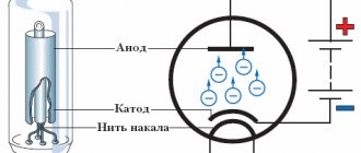
Electricity rectification
Until the end of the 19th century, converting alternating voltage to direct voltage was a problem. With the invention of the diode - first vacuum, and later semiconductor - the situation changed radically. Thanks to its unique properties, the diode perfectly distinguishes polarity and makes it easy to sort currents in the desired direction. At first, separate diodes were used for these purposes, later diode bridges appeared, providing high quality rectification.
Single diode rectifier
A diode conducts current in only one direction, which is why it is called a semiconductor device. If you connect the plus of the voltage source to the cathode of the device, and the minus to the anode, the diode will behave like a regular conductor. If the polarity is changed, the device will close and turn into a dielectric. To answer the question of what this gives, you will have to assemble a simple circuit and again arm yourself with an oscilloscope.
The diagram shows the operation of a semiconductor diode in an alternating current circuit. The oscillogram on the left shows the picture at the output of the transformer - ordinary alternating current. After the diode, everything changes significantly - the negative half-wave of the alternating voltage disappears from the graph. The current has not yet become constant, but it is no longer alternating - there is no movement of the electric charge in the opposite direction. This type of current is usually called pulsating. They can't power electronics yet, but changes are evident. All that remains is to smooth out the pulse peaks. This is done using capacitors.
The diagram shows a half-wave rectifier with a smoothing capacitor. During a positive pulse, the voltage not only powers the load, but also charges the capacitor at the same time. When the pulse ends, the capacitor releases the accumulated energy, smoothing out voltage surges.
Full wave device
Despite the significant progress achieved in converting alternating current into direct current by previous experiments, the result is still far from ideal. The fact is that the frequency of alternating current is quite low (50 Hz), and hanging smoothing capacitors has its limitations. In order to significantly improve the shape of the output signal, you need to increase the frequency.
However, in sockets it is strictly fixed and does not depend on external factors. The negative half-wave of the voltage is cut off by a diode. Changing its polarity is not difficult at all - you just need to add a few diodes to assemble a bridge circuit. The figure shows a full-wave rectifier with four diodes, explaining how a diode bridge works:
When a positive half-wave appears, diodes VD2, VD3 will be turned on in the forward direction and will be open. VD1, VD2 - closed. The half-wave passes freely to the output of the rectifier. When the voltage changes polarity, the pairs of diodes will change places - VD1 and VD4 will open, VD2 and VD3 will close. The negative half-wave will also pass to the output, but will change polarity. The result will be the same pulsed unipolar voltage, but its frequency will double. All that remains is to add a smoothing capacitor and see what happens.
The full-wave rectifier with a smoothing capacitor in the image shows that the problem has been solved: the alternating voltage is converted to direct voltage. Of course, the consistency is not ideal - there are pulsations, but they can be dealt with using filters. In addition, any electronics allows for one or another amount of pulsation.
This circuit, consisting of four diodes, has become classic and is called a diode or rectifier bridge. There is a separate category of electronic devices - rectifier bridges. They consist of four diodes connected to each other in a suitable manner. As an example, you can look at the rectifier bridge KTS402G and its electrical circuit.
AC rectifier 12V
Back at the beginning of the twentieth century, there was a very fundamental dispute between the luminaries of electrical engineering. Which current is more profitable to transmit to the consumer over long distances: direct or alternating? The scientific debate was won by supporters of the transmission of alternating current through high-voltage lines from the substation to the consumer. This system has been accepted all over the world and is still being used successfully.
But most electronic equipment, not only household, but also industrial, is powered by direct voltages, and this led to the creation of an entire branch of electrical engineering - the conversion (rectification) of alternating current. After the vacuum tube was forgotten, the semiconductor diode became the main element of any rectifier.
The circuit design of rectifiers is very extensive, but the simplest is the half-wave rectifier.
Half wave rectifier
The voltage from the secondary winding of the power transformer is supplied to one single diode. Here's the diagram.
That's why the rectifier is called half-wave. Only one half-cycle and a pulse voltage is obtained at the output. Its shape is shown in the figure.
The circuit is simple and does not require a large number of elements. This affects the quality of the rectified voltage. At low frequencies of alternating voltage (for example, as in the mains - 50 Hz), the rectified voltage turns out to be highly pulsating. And this is very bad.
In order to reduce the ripple value of the rectified voltage, it is necessary to take the value of capacitor C1 very large, on the order of 2000 - 5000 microfarads, which increases the size of the power supply, since electrolytes for 2000 - 5000 microfarads are quite large. Therefore, at low frequencies this circuit is practically not used. But half-wave rectifiers have proven themselves well in switching power supplies operating at frequencies of 10 - 15 kHz (kilohertz). At such frequencies, the filter capacitance can be very small, and the simplicity of the circuit does not have such a strong effect on the quality of the rectified voltage.
An example of using a half-wave rectifier would be a simple cell phone charger. Since the charger itself is low-power, it uses a half-wave circuit, both in the input network rectifier 220V (50Hz) and in the output rectifier, where it is required to rectify high-frequency alternating voltage from the secondary winding of the pulse transformer.
The undoubted advantages of such a rectifier include a minimum of parts, low cost and simple circuit solutions. In conventional (non-switching) power supplies, full-wave rectifiers have been successfully operating for many decades.
Full Wave Rectifiers
They come in two circuit designs: a midpoint rectifier and a bridge circuit known as a Graetz circuit. A rectifier with a midpoint requires a more complex power transformer, although it uses half as many diodes as in a bridge circuit. The disadvantages of a full-wave rectifier with a midpoint include the fact that to obtain the same voltage, the number of turns in the secondary winding of the transformer must be twice as large as when using a bridge circuit. And this is no longer entirely economical in terms of copper wire consumption.
The following figure shows a typical full-wave rectifier circuit with a midpoint.
The magnitude of the ripple of the rectified voltage is less than that of a half-wave rectifier and the size of the filter capacitor can also be used much less. You can clearly see how a full-wave circuit works in the figure.
As you can see, at the output of the rectifier there are already two times less voltage “dips” - those same ripples.
The rectifier circuit with a midpoint is actively used in the output rectifiers of switching power supplies for PCs. Since the secondary winding of a high-frequency transformer requires a smaller number of turns of copper wire, it is much more efficient to use this particular circuit. Diodes are used in double diodes, i.e. those that have a common body and three terminals (two diodes inside). One of the terminals is common (usually the cathode). In appearance, a dual diode is very similar to a transistor.
The bridge circuit has gained the greatest popularity in household and industrial equipment. Take a look.
It can be said without exaggeration that this is the most common scheme. In practice, you will meet her more than once. It contains four semiconductor diodes, and, as a rule, an RC filter or only an electrolytic capacitor is installed at the output to smooth out voltage ripples.
This circuit has already been described on the page about the diode bridge. It is worth noting that the bridge circuit also has disadvantages. As you know, any semiconductor diode has a so-called forward voltage drop ( VF ) . For conventional rectifier diodes it can be 1 – 1.2 V (depending on the type of diode). So, when using a bridge circuit on diodes, a voltage equal to 2 x VF , i.e. about 2 volts.
This happens because 2 diodes are involved in rectifying one half-wave of alternating current (then another 2). It turns out that part of the voltage that we remove from the secondary winding of the transformer is lost on the diode bridge, and these are obvious losses. Therefore, in some cases, Schottky diodes are used as part of a diode bridge, whose forward voltage drop is small (about 0.5 volts).
However, it is worth considering that the Schottky diode is not designed for high reverse voltage and is very sensitive to its excess.
Source: https://crast.ru/instrumenty/vyprjamitel-peremennogo-toka-12v
Classic diode bridge
The standard rectifier diode bridge circuit contains, instead of one diode and capacitor, four diodes, combined in the manner shown in the figure. It can be roughly divided into two half-cycles. In each half-cycle there are two diodes operating in one direction, and two that prohibit the passage of current. Positive voltage comes to the anode VD1, negative voltage to the cathode VD3. These diodes open, and VD2 and VD4 close.
When a positive half-cycle is replaced by a negative one, a change in performance occurs. Positive voltage comes to the anode VD2, negative voltage goes to the cathode output VD4. There is a change in direction, but the current flows in the right direction. It turns out that in such a circuit the frequency doubles, due to which it is possible to achieve better smoothing by using a capacitor identical to the first circuit. Thanks to this, the efficiency of the device increases and possible losses decrease.
Operating principle of a classic bridge
When learning how to assemble a diode bridge, do not forget that it is not necessary to solder it from four microelements and select the appropriate capacitor. In most cases, you can purchase a ready-made solution in a store, with selected parameters and known characteristics. The advantages of such an assembly are its small size, uniform thermal conditions and low weight. The main disadvantage is that if one element fails, the entire assembly has to be replaced.
Characteristics of the diode bridge
As we have already discussed, in electronics there are diode bridges in different housings and have different dimensions.
Why is that? The fact is that each diode bridge has some of its own characteristics, which we will talk about in this chapter.
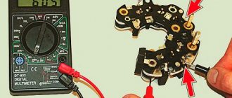
In order not to go far, let's look at the GBU6K diode bridge and use its example to see how to read the characteristics.
In order to understand what kind of fruit it is and what it is eaten with, you need to download its technical description (datasheet). Here is a link to this diode bridge. Below we will consider the main characteristics of the diode bridge, which will be sufficient for the average electronics engineer.
Pinout and housing
So, on the main page we see the pinout. Pinout is which pins are responsible for what and how to correctly connect them to the external circuit.
As you can see, we apply alternating voltage to the middle terminals, and remove constant voltage from the outer terminals. The figure also shows how the diodes in this diode bridge are connected. This information will be very useful to us.
Just below we see a plate that shows us the most important primary characteristics.
Package – type of case. GBU cases look like this.
Maximum current
So, that's sorted out. Next is the next parameter. IF(AV) is the maximum current that this diode bridge can “pull” through itself. The datasheet contains signs and graphs showing what conditions must be met so that the bridge can pull this current through itself without harm to its health.
Therefore, diode bridges in large metal cases are capable of “pulling” a very large current through themselves. If you insert a small diode bridge into some powerful power supply, then most likely it will simply burn out.
In the power electronics industry, they try to use high-power diode bridges; for example, such a diode bridge can “pull” a current of 50 Amps through itself.
Maximum Peak Reverse Voltage
Roughly speaking, this is the reverse voltage of the diode. If it is exceeded, a breakdown will occur and the diode, and therefore the diode bridge, will suffer “kirdyk”
This parameter should also be paid attention to when you rectify the mains voltage. If you supply 220 Volts to the diode bridge, then its peak value will be 310 Volts (220 × √2)
Since I have a GBU6K diode bridge, I need to look at the plate below. As you can see, the peak reverse voltage of the diodes is 800 Volts. This means that such a diode bridge is quite suitable for rectifying the mains voltage.
Charger protection circuit
The simplest protection system can be implemented using several radio elements. A relay with a contact current exceeding the charging current (for example 16 A) is a 5-9 V DC coil. Diode - 1 A, resistor R - 5 times greater than the resistance of the relay coil. Capacitor C - for example, 220 uF 25 V. Of course, the circuit has a drawback - after disconnecting the battery, the relay continues to work until the power supply is turned off.
There are two solutions you can use. First install an additional rectifier diode in the opposite direction to the "zener diode" in the relay coil circuit. The second solution is to put a rectifier diode in the opposite direction instead of the "zener diode" and an LED in the opposite direction plus a resistor and use it as a sign for the reverse connection of the battery.
I also recommend using Schottky diodes, for example, from a computer power supply. These diodes generate less heat than conventional ones. Further reduction of power losses in the rectifier can be achieved by using a transformer with a symmetrical (double) secondary winding. The transformer here is 50 watts, you can't expect much from it, but it still does its job for a long time.
Source
How to make a straightener with your own hands?
If the craftsman has the necessary components, it is quite possible to make a homemade welding rectifier. Provided that all recommendations of specialists are followed, it is guaranteed to provide the process of manual arc welding with direct current, but it will be necessary to use a coated electrode.
It is also permissible to use wire without coating, but only if you have extensive experience in welding matters. For an inexperienced welder, it will be almost impossible to cope with it.
Diode bridge for welding machine.
Coating when melting the electrode prevents the penetration of air components into the molten metal of the welded joint. Without it, contact of molten metal with nitrogen and oxygen will reduce the strength properties of the seam, making it brittle and porous.
First you will need to select or wind up a step-down transformer with your own hands with the required parameters. Assemble the transformer before connecting the diode bridge.
If you choose to manufacture the device yourself, it is important to correctly calculate its elements, including:
- magnetic circuit parameters;
- current number of turns;
- cross-sectional dimensions of busbars and wires.
The work cannot be done without LEDs: they are needed as current conductors in one single direction. The simplest diode rectifier, created using a bridge circuit, is mounted on a radiator for the purpose of heat exchange and cooling.
Powerful diodes for a welding machine, like the VD-200, emit a fairly large amount of thermal energy during operation. To ensure a falling current characteristic, a choke will need to be connected in series to the circuit.
Active variable resistance in such a circuit will provide the welder with the ability to smoothly regulate the welding current. Next, one pole needs to be connected to the welded wire, and the second to the work object.
An electrolytic capacitor in the circuit is needed as a smoothing filter to reduce ripple.
It is not difficult to wind the rheostat on your own, but for such a task you will need a ceramic core and nickel or nichrome wire. The actual wire diameter will be determined by the amount of adjustable current in the welding operation.
The calculation of the rheostat resistance must be carried out taking into account the specific resistance of the electrode, its cross-section and total length.
Electrical circuit for welding with a diode bridge.
The current adjustment step for welding depends on the diameter of the turns. If you correctly assemble the listed parts into a single unit, the welding process will be accompanied by direct current. It would not be superfluous to install a resistor that prevents short circuits during operation.
It can occur when the wire touches metal without igniting the arc. If at this time there is no resistance on the capacitor, it will instantly discharge, a click will occur, the electrode will collapse or stick to the metal.
If you have a resistor, you can smooth out the discharges on the capacitor and make ignition of the electrode easier and softer. Making a device for rectifying weld current with your own hands will allow you to create the most accurate and durable welds.
Scope and purpose
Most often, diode bridges are used in power supplies. In transformer power supplies they are connected to the secondary winding of the transformer
In pulse power supplies - to the 220V network input. In this case, the electronic control circuit and the power circuit of the UPS are powered by a rectified and smoothed (not always) mains voltage (reaches about 300-310 Volts).
There is high-frequency alternating voltage at the terminals of the secondary winding of the switching power supply. In order to straighten it, assemblies of dual Schottky diodes are installed. In this regard, a midpoint rectification scheme is often used.
In cars and motorcycles, three-phase diode bridges are used, assembled according to the Larionov circuit with three additional valves, because a three-phase generator is used to power the on-board network. The bridge in the generator is made in the form of a sector of a circle and is installed on its rear part.
An exception is some modern cars from Toyota and other brands; they use a 6-phase generator to implement a twelve-pulse rectification circuit of 12 valves. This is necessary to reduce ripple and increase output current.
Output voltage regulation
If the power supply voltage needs to be regulated from zero, then the optimal circuit would be a parametric stabilizer with the addition of a variable resistor.
Smooth voltage regulation.
A 1 kOhm resistor connected between the base of the transistor and the common wire will protect the triode from failure if the potentiometer motor circuit breaks. When you rotate the variable resistor knob, the voltage at the base of the transistor will change from 0 to Ust of the zener diode with a lag of approximately 0.6 volts. It must be taken into account that the parameters of the node will be worse due to the use of a potentiometer - the presence of a moving contact (even of good quality) will inevitably reduce the voltage stability at the base of the transistor.
Three-phase bridge
Now that you know what a diode bridge is for and what it is, let's look at a more complex three-phase circuit that produces pulsating current. It is as close to constant as possible and is suitable for use in devices that require a stable supply. The input of this system is connected to a source that supplies three-phase power (of course we are talking about alternating current). This could be a transformer or a generator. The output of the system is an almost ideal direct current, which can be easily smoothed out.
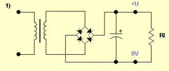
Rectifier circuit
To make a high-quality full-wave rectifier from the connection diagram of a diode bridge with a capacitor, study our drawing. In this case, the current is rectified, which is removed from the step-down transformer winding. Equalization occurs due to an electrolytic capacitor of 5-10 thousand microfarads, which charges and releases the charge into the network. An additional resistor is also introduced into the circuit, which rectifies the current during idle operation. The higher the load, the lower the output voltage, so a stabilizer using classic transistors is connected to it.
Using our diagrams, you can easily figure out how to make a diode bridge and how to use it. We recommend purchasing ready-made devices to save space and not have to select values.
Output voltage stabilization
A stabilizer at the output of the power supply is not always needed. So, if you plan to use a power supply in conjunction with sound-reproducing equipment, then the output must have a stable voltage. And if the load is a heating element, the stabilizer is clearly unnecessary. To power an LED strip, you can do without the most complex power supply module, but on the other hand, a stable voltage ensures independence of the brightness of the glow during changes in the network and extends the life of the LED lamp.
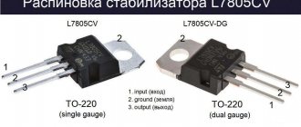
If the decision to install a stabilizer has been made, then the easiest way is to assemble it on a specialized microcircuit LM7812 (KR142EN5A). The connection circuit is simple and does not require adjustment.
Stabilizer for 7812.
The input of such a stabilizer can be supplied with voltage from 15 to 35 volts. A capacitor C1 with a capacity of at least 0.33 μF must be installed at the input, and at least 0.1 μF at the output. The capacitor of the filter unit usually acts as C1 if the length of the connecting wires does not exceed 7 cm. If this length cannot be maintained, then the installation of a separate element will be required.
The 7812 chip has protection against overheating and short circuit. But it does not like reversing the polarity at the input and applying external voltage to the output - its life time in such situations is calculated in seconds.
Important! For load currents above 100 mA, installing an integrated stabilizer on the heat sink is mandatory!
Purpose and practical use
The scope of use of a bridge made of diodes is quite wide. These can be power supplies and control units. It is installed in all devices powered by a 220 volt industrial network. For example, TVs, receivers, chargers, dishwashers, LED lamps.
Cars cannot do without it either. After starting the engine, the generator starts working, producing alternating current. Since the on-board network is all powered by constant voltage, a rectifier bridge is installed through which rectified voltage is supplied. The same constant signal also recharges the battery.
The rectifier device is used to operate the welding machine. True, it uses powerful devices that can withstand currents of more than 200 amperes. The use of diode assembly in devices provides a number of advantages compared to a simple diode. This straightening allows you to:
- increase the ripple frequency, which can then simply be smoothed out using an electrolytic capacitor;
- when working together with a transformer, get rid of the bias current, which makes it possible to more efficiently use the overall power of the converter;
- pass more power with less heat, thereby increasing efficiency.
But it is also worth noting the drawback due to which in some cases the bridge is not used. First of all, this is a double voltage drop, which is especially sensitive in low-voltage circuits. And also, when some of the diodes burn out, the device begins to operate in half-wave mode, which is why parasitic harmonics penetrate into the circuit, which can damage sensitive radioelements.
power unit
Not a single modern power supply can do without a rectifier. High-quality sources are manufactured using bridge rectifiers. The classic scheme consists of only three parts:
- A step-down transformer.
- Rectifier bridge.
- Filter.
A sinusoidal signal with an amplitude of 220 volts is supplied to the primary winding of the transformer. Due to the phenomenon of electromagnetic induction, an electromotive force is induced in its secondary winding and current begins to flow. Depending on the type of transformer, the voltage value is reduced by a certain value due to the transformation ratio.
An alternating signal with reduced amplitude appears between the terminals of the secondary winding. In accordance with the diode bridge connection diagram, this voltage is supplied to its input. Passing through the diode assembly, the alternating signal is converted into a pulsating one.
This form is often considered unacceptable, for example, for sound equipment or lighting sources. Therefore, a capacitor connected in parallel with the output of the rectifier is used for smoothing.
Three-phase rectifier
In production and in places where a three-phase network is used, a three-phase rectifier is used. It consists of six diodes, one pair for each phase. Using this type of device allows you to obtain a higher current value with low ripple. This, in turn, reduces the requirements for the output filter.
The most popular options for connecting three-phase rectifiers are the Mitkevich and Larionov circuits. In this case, not only six diodes can be used simultaneously, but also 12 or even 24. Three-phase bridges are used in diesel locomotives, electric vehicles, on drilling rigs, and in industrial gas and water purification plants.
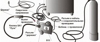
How does the charger work?
Press the START button to apply voltage to the transformer. This activates the relay Pk, which will connect the contacts connected in parallel with the START button. The circuit will lock and conduct as long as there is voltage on the relay coil.
The relay acts as a "fool proof" such as accidental short circuit and constant overload of the rectifier. A short circuit or high current causes a voltage drop and the relay opens, cutting off the power supply to the transformer and protecting the rectifier from damage.
Then there is a voltage switch in combination with LEDs that inform about the current output voltage. It was possible to connect two windings in parallel and then the output current would be greater, but only a single-pole switch was available. Of course, you can make such a modification or use a different transformer and get different voltages, for example 6 V and 12 V. You just need to solder in another relay and LEDs.
Output voltages 14 V and 28 V. Current - 3.5 A or slightly higher. It only took 5 hours to get it up and running (with a break for lunch). The front panel is printed on white adhesive inkjet paper.
The battery must be charged with a current of 1/10 of its capacity, that is, 45 Ah - 4.5 A. Which implies a total charging time of 10 hours. Completely discharging a lead acid battery will have a big impact on its performance.
Of course, the mistake is the absence of a fuse at the output of the rectifier, which would protect the battery in the event of a breakdown of the bridge. In addition, the mains fuse must be placed on the winding.
As for the lack of current regulation. It is probably not necessary given the current efficiency. The maximum current is 3.5 A, which means you can easily charge a car battery of 36 Ah or higher. Overload is also not a threat, because the voltage is low and the current will drop as the voltage increases. Naturally, when charging the battery, do not forget that it is connected (there is no automatic machine here).
It is clear that ideally the charging current should be set at 10% of the battery capacity (for example, 100 Ah is a 10 A charging current or 50 Ah is a 5 A charging current), after which the charging voltage should not exceed 13.8 V during normal charging, and at the accelerated third voltage of 15 V there should be an automatic charging switch when the charging current reaches a small value at the final stage of charging and depends on the battery capacity and its temperature, well, it should be protected from short circuit and overload, but this is all from areas of completely different memory.
If the transformer is 20V, then there will be much more current than 10A, and if it is 10V, there will probably be no current flowing at all. To charge a battery, 5 A is usually enough. Remember one more thing: the higher the current you charge the battery, the faster you will have to replace it with a new one!
Three-phase diode bridge circuit
The diode bridge we considered is used for single-phase rectification; it is called a single-phase bridge. To rectify alternating electric current in three-phase networks, a three-phase diode bridge is used.
It consists of 6 diodes, a pair of diodes for each phase. In this circuit, current flows from the phase with the highest potential, through the load to the phase with the lowest potential. The remaining phase is not connected to anything. If in a single-phase bridge two diodes out of four conducted current, then here 2 diodes also conduct current, and 4 are locked.
Diode bridges are produced as complete components, but if such a part is not available, then you can use 4 separate diodes connected according to the diode bridge circuit.
For surface mount boards it is convenient to use dual diodes. For example, from two diode assemblies BAT54S or BAV99 a full-fledged diode bridge is obtained.
Often, using two assemblies of two diodes is cheaper than using a diode bridge of four diodes in one package or four diodes separately.
Post navigation
8 thoughts on “Diode bridge circuit, principle of operation”
What will a sinusoid look like when two phases are connected?
Tricky question. Connecting 3 diode bridges to three phases with a common neutral. That is, on each diode bridge there are N and L1, N and L2, N and L3 220 volts each. At the output from the bridges there is a divider by 100 and a capacitor on a common negative ground. I thought that there was no phase and no output voltage from the diode bridge, but this is not so. So how does a single-phase bridge work, installed 3 times for each phase and united by a common minus?
I hope I imagined this circuit correctly... If we combine the disadvantages of at least 2 diode bridges, we will get an interphase short circuit through the diodes.
If there was a short circuit between the phases, then the 1n4007 diodes (1A, 1000 V) would evaporate into dust. This means there is most likely no short circuit there.
If there was a short circuit there would be a bang, but there isn’t and everything just works crookedly.
How much constant will there be at the exit from the bridge, provided that the phase is equal to 220 V?
If you do not use filters, then after a single-phase diode bridge there will be no constant voltage, there will be a unipolar one. If you install a ripple smoothing capacitor, you can achieve voltage: multiply the input voltage by the root of 2, minus the double drop across the diodes (this is about 2 V). If you look at three-phase circuits, there is less ripple even without filters. The average output voltage will greatly depend on the switching circuit. For example, for a triangle-Larionov circuit, the average output is 1.35 of the current input. And for the Larionov star the coefficient is 2.34.
Let's clarify the terminology a little - then after the real capacitor there will also be no constant voltage. In all cases (even after a single-phase diode bridge) there will be a constant component and an alternating one. In this case, the constant component in the first case will seem to be equal to half the effective voltage minus the drop across the diode (I could be wrong in the quantitative assessment, I’m too lazy to count).” And the variable in the second case will be significantly smaller: the smaller the closer the real capacitor is to the ideal infinite capacitance (with a real voltage source).
Parametric stabilizer
If for some reason an integrated stabilizer is not available, you can make a unit on a zener diode. It is necessary to select a zener diode with a stabilization voltage of 12 V and designed for the corresponding load current. The highest current for some 12-volt domestic and imported zener diodes is indicated in the table.
| Zener diode type | D814G | D815D | KS620A | 1N4742A | BZV55C12 | 1N5242B |
| Load current | 5 mA | 0.5 A | 50 mA | 25 mA | 5 mA | 40 mA |
| Stabilization voltage | 12 volts | |||||
Circuit diagram of a simple parametric stabilizer.
The resistor value is calculated using the formula:
R= (Uin min-Ust)/(In max+Ist min), where:
- Uin min – minimum input unstabilized voltage (must be at least 1.4 Ust), volts;
- Ust – zener diode stabilization voltage (reference value), volts;
- In max – highest load current;
- Ist min – minimum stabilization current (reference value).
If a zener diode for the required voltage is not available, it can be made up of two connected in series. In this case, the total voltage should be 12 V (for example, D815A at 5.6 volts plus D815B at 6.8 volts will give 12.4 V).
Important! You cannot connect zener diodes (even of the same type) in parallel “to increase the stabilization current!”
Zener diodes are not connected in parallel.
You can power up the parametric stabilizer in the same way - by turning on an external transistor.
Powerful stabilizer circuit.
For a powerful transistor, a radiator must be provided. The supply voltage in this case will be less than Ust of the zener diode by 0.6 V. If necessary, the output voltage can be adjusted upward by turning on a silicon diode (or chain of diodes). Each element in the chain will increase Uout by approximately 0.6 V.
Stabilizer circuit with zener diode and diode.
Using the Schottky barrier
The use of a Schottky diode is justified in two cases. Firstly, when you need to rectify high-frequency current. The Schottky barrier is ideal for such a task, because it has a low junction capacitance and, accordingly, is fast-acting. Secondly, when it is necessary to rectify a large current of tens or hundreds of amperes. In this case, the part performs well due to the low voltage drop and low heat generation.
Diode bridges in the world of electronics play the role of a matching element. With their help, you can connect devices that require direct current to a network of alternating voltage convenient for transmission. There are a lot of such devices in everyday life; they are extremely important for a person’s comfortable life.
Capacitor Specifications
For a transformerless power supply, a capacitor designed for the amplitude (or greater) value of alternating voltage is suitable. If the effective voltage value is 220 V, then the amplitude value is calculated using the formula 220 * = 311 V (nominal 400 V). It is better to choose film capacitors; capacitive elements of the K73-17 series are optimal.
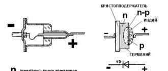
Planar semiconductor diodes
Along with good conductors and insulators, there are many substances that occupy an intermediate position in conductivity between these two classes. Such substances are called semiconductors. The resistance of a pure semiconductor decreases with increasing temperature, unlike metals, whose resistance increases under these conditions.
By adding a small amount of impurity to a pure semiconductor, its conductivity can be significantly changed. There are two classes of such impurities:
Figure 1. Planar diode: a. diode device; b. designation of a diode in electrical diagrams; V. appearance of planar diodes of various powers.
- Donor - converting pure material into an n-type semiconductor containing an excess of free electrons. This type of conductivity is called electronic.
- Acceptor - converting the same material into a p-type semiconductor, which has an artificially created lack of free electrons. The conductivity of such a semiconductor is called hole conductivity. A “hole,” the place where an electron has left, behaves similarly to a positive charge.
The layer at the boundary of p- and n-type semiconductors (pn junction) has one-way conductivity - it conducts current well in one (forward) direction and very poorly in the opposite (reverse) direction. The structure of a planar diode is shown in Figure 1a. The base is a semiconductor plate (germanium) with a small amount of donor impurity (n-type), on which a piece of indium is placed, which is an acceptor impurity.
Once heated, indium diffuses into the adjacent regions of the semiconductor, converting them into a p-type semiconductor. A pn junction occurs at the boundary of regions with two types of conductivity. The terminal connected to the p-type semiconductor is called the anode of the resulting diode, and the opposite one is called its cathode. An image of a semiconductor diode on circuit diagrams is shown in Fig. 1b, the appearance of planar diodes of various powers is shown in Fig. 1st century
Practical use
In practice, the diode bridge has a fairly wide range of applications - this includes digital technology, power supplies in personal computers, laptops, various devices, car generators powered by low DC voltage. In addition, they can be found in sound reproduction systems, measuring equipment, television and radio broadcasting, and they are installed in a number of different devices throughout the house. To better understand the role of the diode bridge in these devices, we will look at several specific circuits in which it is used.
Examples of diode bridge circuits and their descriptions
One of the simplest circuits using a diode bridge is a charger used for equipment powered by low voltage. Let's look at one of these options using the following example:
Rice. 5. Charger circuit
As you can see in the figure, from the step-down transformer T1 the voltage from alternating 220V is converted to alternating at a level of 7 - 9V. After this, the reduced voltage is supplied to the diode bridge VD, from which it is rectified through the smoothing capacitor C1 to the KR microcircuit. The rectified voltage from the microcircuit is stabilized and supplied to the connector terminals.
Rice. 6. Flashlight diagram
The figure above shows an example of a flashlight circuit; this model is connected to a 220V household network through a socket, which is represented by connecting connectors X1 and X2. Next, the voltage is supplied to the VD bridge, and from it to the DA1 chip, which, if there is input power, signals this through the HL1 LED. After this, the power supply is supplied to the GB battery, which is charged and then used as the main power source for the flashlight lamp.
Example of a welding unit diagram
Here is an example of a welding unit circuit in which a diode bridge is installed immediately after a step-down transformer to rectify the electric current. Due to the complexity of the circuit, further consideration of the operation of the device is impractical. It is worth noting that there are other devices with an even more complex operating principle - switching power supplies, PWM modulators, converters, etc.
Types of power supplies
Today, switching voltage sources are widely used. Compared to traditional transformer circuits, they have a significant advantage in energy efficiency and weight and size indicators. It is believed that at load currents of more than 5 amperes they have undeniable preferences. But they also have disadvantages - for example, the generation of RF interference into the supply network and into the load. And the main obstacle to home assembly is the complexity of the circuits and the need for special skills to make winding parts. Therefore, it is better for a semi-skilled home craftsman to start making a power supply according to the usual principle with a network step-down transformer.
Physical processes
The operating principle of a diode bridge is based on the ability of a pn junction to pass current in only one direction. A pn junction is understood as a contact between two semiconductors with different types of conductivity. The boundary separating the regions is characterized by the width of the forbidden zone, which prevents the passage of charges. On one side there is the p region, in which the main carriers are holes (positive charge), and on the other, the n region, where the majority carriers are electrons (negative charge).
Being isolated from each other, in each region the elementary particles perform random thermal vibrations, due to which their released energy is compensated and the resulting current is zero. When these areas come into contact, diffusion currents arise due to the attraction of charges to each other. As a result, the particles collide and recombine (disappear). In the contact zone, carriers become depleted and their movement stops. A state of dynamic equilibrium is established.
When an electric field is applied to the pn junction, the picture changes. With forward bias, that is, when the positive pole of the power source is connected to the p region, and the negative pole to the n region, the main carriers are introduced into the region. Because of this, the bandgap width decreases, and particles freely begin to pass through the barrier, forming a current. If the polarity of the power source is changed, then even greater depletion of the layers will occur, as a result, the barrier will increase, and the current will not arise.
Thus, depending on the polarity of the signal applied to the junction, the band gap increases or decreases. If an alternating signal is applied to an element whose operation is based on a pn junction, then as a result, forward and reverse voltage will be alternately applied to it. Accordingly, it will delay part of the signal and transmit part of it.
If you take a measuring device that can show the waveform (oscilloscope), then at the output of the radio element you can see pulses, the duration of which is determined by the half-wave period. That is why the diode is called a rectifier, although the name pulse converter is more suitable for it. That is, a device that converts an alternating signal into a burst of pulses.
Classic model
Classic stabilizers are a large class of devices assembled based on semiconductor parts such as bipolar transistors and zener diodes. Among them, the main function of maintaining the voltage at 12 V is performed by zener diodes - a type of diodes connected in reverse polarity (the plus of the power supply is connected to the cathode of such a semiconductor device, and the minus to the anode), operating in breakdown mode. The essence of how these semiconductor parts work is as follows:
- When the voltage of the power source connected to the zener diode is less than 12 V, it is in the closed position and does not participate in adjusting this characteristic of the electric current.
- When the threshold of 12 Volts is exceeded, the zener diode “opens” and maintains this value in the range specified by its characteristics.
If the voltage supplied to the zener diode exceeds that stated as the maximum by the manufacturer, the device very quickly fails due to the effect of thermal runaway.
In order for any model of zener diode to serve as long as possible, it is recommended to specify, according to its specification, the voltage range and current strength in which it should be operated.
Depending on the connection, there are two versions of the classic stabilizer: linear - the adjusting elements are connected in series with the load; parallel – voltage stabilizing devices are located parallel to the powered devices.
Operating principle
Let's figure out how a diode bridge works. Let's start with the fact that diodes pass current in one direction. AC voltage rectification occurs due to one-way conduction of diodes. Due to their correct connection, the negative half-wave of the alternating voltage is supplied to the load in the form of a positive one. In simple words, it reverses the negative half-wave.
For simplicity and clarity, let's consider its operation using the example of a single-phase full-wave rectifier.
The operating principle of the circuit is based on the fact that diodes conduct current in one direction and is as follows:
- An alternating sinusoidal signal, for example 220V from a household electrical network, is supplied to the input of the diode bridge (in the connection diagram, the input of the diode bridge is designated as AC or ~).
- Each half-wave of sinusoidal voltage (figure below) is passed through a pair of valves located diagonally in the diagram.
The positive half-wave is transmitted by diodes VD1, VD3, and the negative half-wave by VD2 and VD4. You can see the signal at the input and output of the circuit below.
This signal is called rectified pulsating voltage. In order to smooth it out, a filter with a capacitor is added to the circuit.
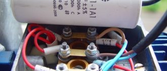
Rectifier for charging 12/24 V batteries
People familiar with the minibus fleet asked us to make a charger for charging 12 V and 24 V batteries. Since it will be used by completely untrained people, it was decided to make it resistant to errors from users who are far from electronics.
After looking at several different schemes from the 2Schemes , it turned out that it was pointless to make any kind of automation and electronics. The rectifier simply needs to provide the correct voltage and, if necessary, the optimum current. Which is exactly what car batteries need.
12 volt diode bridge circuit: instructions and assembly
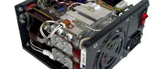
The power supply consists of two modules, where the first is a step-down transformer, and the second is a diode bridge that converts one type of voltage to another.
A suitable transformer is selected. The primary winding is located using a tester. Its resistance should be the greatest. By testing with a multimeter in resistance measurement mode, the required ends are found. Then other pairs are found and markings are made.
220 V is supplied to the primary winding. Then the tester is switched to the alternating voltage measurement mode and the voltage on the remaining windings is measured. Should select or wind one at 10V
It is important that the voltage is not 12 V, since after the capacitive filter it increases by 18%
The transformer is selected for the required power, after which a reserve of 25% is taken.
4 diodes are twisted into a diode bridge and the ends are soldered. Then the circuit is connected, a 25 V and 2200 μF capacitor (electrolyte) is connected to the output and tested in operation.
Increasing the output current of the stabilizer
The above circuit allows you to load the stabilizer with a current of up to 1.5 A. If this is not enough, you can power the unit with an additional transistor.
Circuit with an NPN structure transistor
External NPN transistor.
This circuit is recommended by the developers and is included in the datasheet for the chip. The output current should not exceed the maximum collector current of the transistor, which must be equipped with a heat sink.
Circuit with pnp transistor
If there is no semiconductor triode of the npn structure, then you can power the stabilizer with a semiconductor triode pnp.
External PNP transistor.
A silicon low-power VD diode increases the 7812's output voltage by 0.6 V and compensates for the voltage drop across the transistor's emitter junction.
How to determine the anode and cathode of a diode
1) on some diodes the cathode is marked with a stripe that differs from the color of the body
2) you can check the diode with a multimeter and find out where its cathode is and where its anode is. At the same time, check its performance. This method is ironclad ;-). How to check a diode using a multimeter can be found in this article.
It is very easy to remember where the anode is and where the cathode is, if you remember the funnel for pouring liquids into the narrow necks of bottles. The funnel is very similar to the diode circuit. We pour it into the funnel, and the liquid flows very well, but if you turn it upside down, try pouring it through the narrow neck of the funnel ;-).
No tags for this post.
How to get 12 Volts?
In modern household networks, a huge number of appliances and devices are powered by reduced voltage. As a rule, these are low-current devices that use 12 volts in their power circuit: gas heaters, hand-held power tools, portable and stationary lamps, children's toys and much more.
Due to their widespread use, ordinary people try to organize power for such devices on their own, so in this article we will look at how to get 12 Volts in various ways.