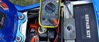
There are many radio elements in household appliances and various devices, thanks to which everything works as it should. The malfunction of even one part has a bad effect on the operation of the entire mechanism, which may even stop functioning. One of the representatives of such important elements of electrical engineering is the diode bridge. Its breakdown does not lead to anything good, but a multimeter helps to notice the malfunction in time. We will tell you how to check a diode bridge with a multimeter, but first let’s remember what kind of part it is and how it works.
How to check a generator diode bridge with a multimeter
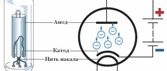
The diode bridge in the generator is a kind of rectifier, with the help of which the alternating current generated by the generator is converted into direct current. It includes 6 semiconductor diodes, 3 of them with a positive value, and 3 with a negative value. Each of these groups passes current only in one, strictly defined direction.
Alternating current is used when it needs to be transmitted over long distances. Electrical appliances installed in the car require constant current, including charging the battery. Since the generator is capable of producing only alternating current, a diode bridge is needed to convert it to direct current.
The design includes two metal plates that conduct electric current. Diodes are installed on their plane in order of priority. The alternating voltage produced by the generator changes the direction in which the electrons move. In order to obtain a constant voltage, it is necessary to redirect their movement in the so-called wrong direction; as a result of further operation of the phases, a constant current will be created. In this circuit, the battery serves as a kind of capacitor that successfully dampens voltage fluctuations. If necessary, you should check the generator using a multimeter.
Quite often the diode bridge fails. A similar situation occurs when the polarity of the battery is not observed, or the electrical circuit in the generator itself is short-circuited. Any malfunction of the diode bridge negatively affects the entire on-board network. If one of the diodes breaks or the diode is broken, then dips appear in the stable pulsating voltage at the generator output, since the faulty diode stops supplying voltage to the on-board network.
The battery takes on some compensation for dips using its own resources, but the overall network voltage is still reduced. In addition to affecting stability, dips lead to electromagnetic interference, which negatively affects sound-reproducing equipment. If there are a large number of such violations, a mandatory check of the diode bridge will most likely be required. For this purpose, you will have to check the generator for functionality with a multimeter, having first removed it from the engine. The diode bridge is disconnected and called by the tester.
It is advisable to use the instruction manual during disassembly as this operation may vary from machine to machine. On some models, the bridge is secured with bolts, while on others it is simply soldered. Marks are applied to the diode bridge and generator to avoid confusion during subsequent assembly.
- The multimeter must be switched to resistance measurement mode and the sound indication must be set.
- Next, the probes of the measuring device are connected to each terminal of the diode. The negative terminal - “minus” is connected to the central steel or aluminum plate, and the positive terminal is connected to a metal core made in the form of a tinned bare wire, the diameter of which must be at least 1 mm.
- To check each diode, you must first touch the core or central plate with one probe, and the opposite terminal of the diode with the other probe. After this, the probes must be swapped.
- If the diode is working properly, the multimeter will produce sound signals only when the probes are in a certain position. If the tester beeps with all connection options, this indicates that the diode is broken. If there are no sound signals at all, then the diode is broken. The instrument should emit audible signals when only one side of the bridge is being inspected.
There is another method for checking the generator with a multimeter. In this case, resistance is used - the main physical quantity. To carry out measurements in this way, the switch must be set to 1 kOhm. Touches with probes are carried out as in the previous version. When checking one direction, the device should produce a result of 500-800 Ohms, and when checking the other, infinity. In this case, all bridge diodes are in working condition.
Principle of operation
The operation of a diode semiconductor bridge that conducts current is simple. The principle of operation is based on the property that a semiconductor diode passes electric current in one direction and does not pass in the other. So, if the charges are connected correctly, current will flow through the device.
The difference between alternating current and direct current is that it can only move in one direction. Moreover, do this in one half-cycle. During the other half of the period, it can make the opposite movement. When several diodes are connected in a circuit, they will begin to move, creating a direct current.
It is easy to assemble a diode bridge circuit. Anyone can do this. It includes four diodes, which are connected to each other by a square. Current is supplied to several opposite corners from the generator apparatus. From several other opposite angles the constant is removed. During the first period, several electrodiodes are opened and the alternating voltage wave is rectified. In the second period, several more diodes are opened. Thus, the second wave is transformed. The result is a constant voltage with a pulse frequency several times higher than that with alternating voltage.
Interesting! The presented scheme has its pros and cons. To use rectified current, the pulse component must be smoothed with a filter. Thanks to rectification, it is possible to power the transformer and reduce its volume. Among the disadvantages, note the fact that power is lost due to thermal dissipation, the voltage drops twice and the device breaks down if one diode fails.
How the device works
Let's figure out why the diode bridge in a car generator burns
The main component in the electrical system of any vehicle is the generator. Without this unit, a serviceable car, even with a new, fully charged battery, will not drive for long. Therefore, this unit must be in working order at all times, that is, fully operational.
In this case, initial diagnostics of the car can be carried out without leaving the driver’s seat. However, repairs or detailed inspections require dismantling the DC source and then disassembling it to gain access to the diodes. But before this, the motorist must know the basic ways to check the diode bridge.
Methods for diagnosing performance
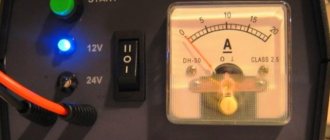
To independently detect faults in the rectifier unit, you will need a multimeter (tester) or a 1–5 W, 12V lamp. The bridge is removed from the generator. It is recommended to diagnose each diode one by one.
Multimeter (tester)
Measuring DC and AC current with a multimeter will help diagnose diode failure
The tester is set in ohmmeter (1 kOm) or diode monitoring mode. One electrode is tightly fixed to the frame of the diode or the plate on which it is fixed, the second to its terminal. Then the electrodes are swapped. For a working diode, one indicator will be equal to 400–800 Ohms, depending on its power, the second will be equal to 1 (tends to infinity), which indicates a closed (locked) direction. The remaining diodes are checked in the same way.
The operating resistance on all semiconductors should not differ significantly. The permissible difference in resistance of semiconductors on one wafer is 5 units. A diode with an exceeding deviation does not work well, which will lead to charging problems.
Units on both sides indicate diode damage. When the tester produces any values when changing electrodes, the diode has a short circuit.
It is acceptable to set the multimeter to test mode, but this method is less accurate. In this case, with a correctly functioning diode in one position of the probes, the tester will emit a sound signal, and in another it will be silent. A squeak or silence on both sides when changing electrodes indicates damage to the diode.
Video verification instructions
More information about diagnostics on a VAZ (video with diagrams from a practitioner)
A light bulb
In the absence of a tester, the operating condition of the semiconductors is checked with a test lamp. Why connect the battery to the lamp and form a gap near it, the stripped ends of which will serve as probes to facilitate testing. The probes are simultaneously pressed against the body and the diode terminal, then the polarity is changed. In one position, the lamp will light for a working semiconductor, but not in another.
Circuit for checking a diode bridge using a light bulb
LED diagnostics
SMD elements of LED strips, infrared types, and laser samples are tested using a method similar to testing rectifier diodes. The exception is representatives of this group with high power. To carry out diagnostics, you will need a stabilized power source.
- The limits of procedures performed on the device are up to 10 A. By adding a current-limiting resistance, the charging element can be used as a power supply.
- After measuring the rated current parameters, the power supply is turned off.
- In the used testing option up to 20 V, the part being tested is connected in parallel to the element being diagnosed.
- The operating voltage indicators are recorded after the power supply is started.
- Based on the analysis of data on the indicators required in the inventory and the actual ones, the performance of the element under study is determined.
Why does the gene burn out?
There are many reasons leading to gene (diode) burnout. However, it is customary to highlight the most common:
- dirt or oil has penetrated into the bridge, causing a short circuit;
- on Japanese cars - due to a voltage drop when the generator wears out;
- due to the fault of the voltage regulator, which supplies the rotor, and that, accordingly, to the diode bridge;
- due to a “bad” battery (there are batteries that consume 40A and easily kill the gene);
- the gene was flooded with water;
- the standard fuse responsible for protecting the gene during short circuits has failed;
- The battery terminals were installed incorrectly.
Thus, the generator on the car burns out for various reasons. We are always talking about the combustion of the regulator and diode bridge. Everything is checked quickly based on superficial symptoms. If you need to be 100 percent sure, you have to disassemble the generator.
- Absolutely legal (Article 12.2);
- Hides from photo and video recording;
- Suitable for all cars;
- Works through the cigarette lighter connector;
- Does not cause interference to radios and cell phones.
Preliminary checks
The phenomena listed above are external manifestations of malfunctions. For example, a car behaves this way when the battery has expired or is faulty. Primary diagnostics of serviceability is carried out by the corresponding icon on the on-board computer display (a stylized battery with terminals), which does not light up or flashes when the engine is running. Its shutdown indicates that the power supply to consumers has been transferred from the battery to the generator.
Restoring the normal technical condition of the vehicle's electrical equipment begins with localizing the location of the fault. Taking this feature into account, before testing the bridge, the tension of the generator belt, the serviceability of the relay regulator, the voltage on the battery and the absence of oxidation of the electrical circuit terminals are first checked.
We are looking for a diode bridge on the board
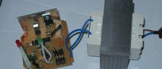
You can check both the diode bridge installed on the board and the one soldered from it; the second option is considered more accurate, since the test is not affected by other circuit elements, but it should be remembered that some testing methods can only be implemented in a working device. If the design of the device is quite complex or the board is overcrowded with parts, it is advisable to look for a diode bridge in the following locations:
- in power supplies;
- in secondary circuits of transformers;
- at the output of generators;
- in front of the batteries.
After detecting a diode bridge, it is necessary to inspect its housing or each diode individually. An experienced electrician will automatically notice the location of the inputs, but if it is difficult for you to focus on memory, you can draw a diagram in relation to your situation. On such a diagram you need to display the positive terminal and the negative terminal, the AC voltage input terminals.
It should also be noted that the malfunction may not only lie in the diode bridges, so during the inspection it is worth carefully inspecting all elements and parts, and when checking, do not exclude the integrity of the object.
Why do rectifiers burn out on generators?
There are several reasons for this. The main ones:
- Moisture and dirt getting on the plates with the diode assembly;
- Mechanical damage to the inside of the generator;
- Failure to observe polarity when lighting a cigarette;
- Short circuit of electrical wires;
- Excessive load in the vehicle's on-board network.
Keep the generator clean, monitor the insulation of the wiring, and do not disconnect the terminals from the battery while the engine is running. Replace worn generator bearings on time. Carry out preventive maintenance on your vehicle's electrical equipment more often.
If you adhere to these rules, then the possibility of the diode bridge breaking down will sharply decrease.
Often, car enthusiasts are faced with the problem of a breakdown of the generator rectifier or diode bridge. This device is necessary to provide the car engine with full-wave current. At one time, the diode bridge became a replacement for the collector, which performed the functions of voltage rectification, and also increased the efficiency of the transformer with stabilization of the magnetic flux level.
If a malfunction is detected
Diodes are attached to the wafers by pressing into a hole of a smaller diameter, so replacing a faulty semiconductor yourself is a troublesome task that does not guarantee 100% success. Diode bridges for domestic cars are inexpensive, so if a fault is detected, it is replaced with a new one.
Rectifier units of modern foreign cars cost a lot of money, so replacing the diode in such a bridge is economically justified. It is better to entrust this procedure to a specialist.
The quality of operation of the entire electrical system of the car depends on the condition of the diode bridge. If the previously listed signs of malfunction appear, you must immediately diagnose, repair or replace it.
Useful tips
As practice shows, the diode bridge of the generator often burns out precisely as a result of the carelessness of the car owner himself. If there is an incorrect connection of the battery terminals, the load on the generator is prohibitively high, then the diodes burn quickly.
In the case where there is no new diode bridge, then the solution is to replace the failed individual elements. To replace, you need a powerful soldering iron, as well as known-good diodes in stock.
In cases where the generator is not old, and the breakdown occurred due to an accidental mistake by the owner (for example, after lighting the car), you can limit yourself to only repairing the generator. Often, in this case, there is no need to fear that other diodes will also begin to burn out quickly (provided that the rules are followed during further operation).
Causes and main signs of diode bridge failure
The main cause of rectifier failure is considered to be thermal breakdown of the diode, as a result of which the semiconductor loses its functions. That is why the bridge is installed on the engine cooling radiator, which protects the part from thermal effects. The most common cause of semiconductor failure is moisture getting into the hood area.
Visual diagnostics of the element’s condition is quite difficult, so for a high-quality check of the diode bridge you need a special device - a tester. The presence of a breakdown can be indicated by voltage problems and sounds that accompany the vehicle while driving.
A faulty part can be determined by the following signs:
- while driving the vehicle there is dim light from the headlights;
- sudden appearance of noises of different tones;
- steering errors;
- rapid battery discharge;
- malfunction of the air conditioner and car acoustics;
- high generator temperature;
- when checking the diode bridge with a tester, the generator windings “ring” at the + terminal;
- Turning on the warning indicator together with starting the engine;
- The generator output voltage is less than 13.5 Volts.
The most important sign of problems with a diode bridge is the rapid discharge of the battery. For example, if last night the charge of the device was at a high level, and in the morning it completely disappeared, or was discharged a couple of minutes after starting the engine, most likely your diode bridge has failed.
How to choose a tester?
Choosing a tester is no less important than diagnosing a rectifier, and a correctly selected device is a guarantee of successful equipment diagnostics.
If in the recent past, when purchasing a multimeter, car owners were faced with a shortage of equipment, now they can be purchased in almost every store.
Earlier we mentioned the incandescent lamp and, in fact, this is the cheapest device. Such a tester is suitable for identifying small faults in the rectifier, but is not suitable for finding more complex problems. Therefore, it is recommended to purchase modern multimeters, many of which are automatic and come with LCD screens.
In conclusion, I would like to draw attention to the following things:
- every car owner should be able to check the diode bridge on the generator, since this is considered a basic skill in servicing your own car;
- “conductivity”, “tseshka” and other testers do not always show the final result even when used correctly, so it is better to diagnose a breakdown using several devices;
- in case of replacing the generator rectifier, do not forget to protect it from moisture;
- buying parts on a spontaneous market will be cheaper than in a store, but there is a risk of buying a faulty product;
- To accurately diagnose a bridge, it is better to purchase several multimerts.
The most common car malfunctions, including the VAZ 2107, include problems with electrical equipment. Since the power source in the vehicle is the generator and the battery, the starting of the engine and the operation of all consumers depend on their uninterrupted functioning. Since the battery and generator work in tandem, the service life and duration of operation of the former depends on the latter.
Signs of diode failure
The main problem in a rectifier bridge is the diodes. You should start checking the unit that generates electricity in the car only after identifying the following indirect problems:
- the voltage at the generator output terminals is below 13.5 Volts;
- the indicator on the instrument panel inside the car continues to light after starting the power unit;
- the arrow on the voltmeter shifts to the red zone when readings are taken;
- The battery indicator does not light up after turning on the ignition.
Similar symptoms are detected when the voltage regulator breaks down; therefore, its serviceability is checked first. There are various reasons why a rectifier bridge fails, which requires its repair or complete replacement.
"Symptoms" of malfunctions
A bridge test should be performed if the following signs are present:
- Incorrect operation of vehicle current consumers. Dim light from the headlights, spontaneous turning off of the audio system, air conditioning - these are clear “symptoms”. If you measure the voltage from the output of the device, the measuring device will show less than the required 13.6 V.
- The "Check Battery" light does not turn off after starting the engine. The voltmeter needle on the dashboard is in the “red” zone or close to it.
DM functions
If we recall the physics course from school, we will conclude that there are two types of electric current. It is constant and variable. How are they different from each other?
There's nothing complicated here. The key difference is that alternating current has charged particles that move in different directions. In the case of direct current, movement always occurs in only one direction.
I would like to note that alternating current has noticeably better economic characteristics. They cope more effectively with transmitting current over fairly long distances. The only problem is that most electrical appliances in vehicles are powered by direct current. In order for a vehicle to function properly, electrically dependent equipment must receive a certain amount of direct current. The generator itself cannot provide it, since it produces alternating current.
Our today's hero allows us to solve this problem. That is, a diode bridge. It looks like a pair of metal conductive plates. They contain diodes that act as semiconductors. They are installed in a certain sequence.
The DM allows current to pass, but the bridge sets one direction. That is, the straightening process occurs. Another nuance is that the bridge sets traffic in only one direction. Namely, from the generator to the on-board network.
The serviceability of the DM is not eternal. Periodically, the generator element fails
And it doesn't matter what kind of car you have. It could be:
- VAZ 2107;
- VAZ 2114;
- Toyota Corolla;
- Lada Priora;
- Nissan Qashqai;
- Daewoo Matiz;
- VAZ 2110;
- Mitsubishi Lancer;
- Ford Mondeo;
- UAZ Patriot;
- Hyundai Solaris, etc.
Regardless of the car, you can and should check the functionality of the device with your own hands. For these purposes, it is important to use a tester.
If you are not sure about the correctness of your actions, watch visual videos. Don’t rush to blame the bridge for everything. Without disassembling or unsoldering the diodes, first make sure that it is faulty.
This is interesting: How to check a car battery - capacity and charging
Safety regulations
Depending on where and which diode bridge you are testing, consider the following:
- Many modern units operate with high-voltage power supplies, that is, the bridges in them are under high voltage! Therefore, before testing, disconnect the device from the network and discharge the smoothing capacitors, which are in the photo under the scarlet arrows. This is easy to do: you can short-circuit the capacitor terminals for a second with a screwdriver, while holding it by the insulating area. If you do not take this point into account, you can lose your life!
- When the repair is completed, you should not directly connect the device to the network. First, turn it on through a lamp (150-200 W). If everything is ok, it will burn a little. But a bright light indicates a short circuit.
- Take care of your eyes and more. Parts of impulse units can explode if repaired incorrectly, and this is very dangerous!
Now you know how to test a diode bridge with a multimeter. Take on the job if you have thoroughly studied safety precautions and are confident in your abilities.
Share your experience in the comments.
We wish you safe and accurate measurements!
How to ring a diode bridge made of discretely arranged diodes
All parts of the bridge circuit can be ringed without desoldering. To do this, you need a multimeter that has a diode testing mode, usually combined with an audio test. The essence of the test is to measure the voltage difference between the probes.
How to properly check the serviceability of a diode bridge with a tester:
- First, make a direct connection to the device. To do this, a red probe is connected to the anode, and a black probe is connected to the cathode. With this connection, current flows freely. For a silicon diode, the voltage drop across the pn junction is approximately 500-700 mV. For Schottky diodes, the voltage drop at the transition between zones is lower and equal to approximately 300 mV.
Direct connection of the diode bridge
Next, the reverse connection is made. The red probe is connected to the cathode, and the black one to the anode. For a healthy semiconductor, the voltage drop value will be 1 or more than 1000 (usually 1500).
Reverse connection of the diode bridge
If, as a result of the test, high values are observed in both directions or an audible signal is triggered, then the diode bridge is broken.
How to check without installation
You can check household or automotive equipment on site without having to disassemble the generator and solder off the parts. This is not a difficult task. To do this, you need to unscrew the existing generator wires with a voltage regulator, which play a big role in the process, set the control multimeter tester to ohmmeter mode and connect the lamp to the transport electrical equipment.
Test diagram without installation
Thanks to this method, you can quickly check the serviceability of the entire bridge or individual diodes without looking at the table of contents of textbooks. Semiconductors can also be tested using a lamp. To do this, the battery is connected to the lamp and a break is made near it. The stripped ends will serve as feeler gauges to make checking easier. Together they attach to the body part and diode terminals in one polarity, and then in the other. In the first case, a working semiconductor will light the light bulb, but in the other case this will not happen. In this case, a quiet squeaking sound will be heard, and a current conversion will occur.
Multimeter testing method
The most informative is a full check of the diode bridge. To implement it, you will need a multimeter, tester or Tseshka - any of these devices is equally suitable for measurements.
Follow these steps:
- Determine the purpose of the pins.
The method is universal, so you can check both the diode rectifier as an assembly and the design of individual parts without disassembling them. - Install the multimeter probes.
Install the multimeter probes into the appropriate connectors on the device, observing the color markings (black - minus, red - plus). Switch the switch to dialing mode. - Use the negative lead of your multimeter.
Connect the negative probe of the multimeter to the plus of the diode bridge, and the positive one in turn to each of the AC voltage terminals.As a result of touching, the opening voltage of the diodes should be displayed on the multimeter display; at both points this measurable value is the same for each measurement. Otherwise, the assembly is faulty.
- Swap the tester probes.
Next, you need to swap the tester probes - set the red one to positive, and alternately touch the black leads to the AC voltage terminals.The display will display a unit, indicating an infinitely high resistance - with reverse polarity, the diodes remain closed. Otherwise, if any voltage is displayed, the bridge is broken.
- Use the positive lead of your multimeter.
Touch the positive probe of the multimeter to the negative terminal of the diode bridge, and touch the negative probe in turn to the variable terminals. In both cases, the voltage drop should be displayed on the display. - Use the black probe.
Install the black probe on the negative terminal of the assembly, and connect the red probe to the variable terminals. There must be a unit in both positions on the multimeter, otherwise the element is broken.
Diode bridge: features and principle of operation
A diode bridge is a circuit that is assembled from connected diodes and converts alternating voltage to direct voltage. It is used in almost all mechanisms that are powered from the network, which is logical: the voltage in the network is alternating, and the electronics operate on constant voltage. Therefore, another name for such a circuit is an AC rectifier.
Despite its simplicity, such a device is much better than a conventional diode. In theory, the use of one semiconductor gives the desired result - voltage conversion. In practice, the output pulsates strongly, so it is not suitable as power supply for electrical circuits. But switching on several diodes in a specific way gives an almost ideal result: the excess half-wave is not cut off, but turned over, due to which the rectification efficiency is greatly increased.
Multimeter
Testing with a tester allows you to determine the serviceability of the diode or confirm its failure. The most commonly used measuring instrument in this area is the multimeter. It is used to measure all the main parameters of electrical circuit components: current, voltage, resistance, capacitance. More expensive models are able to measure the temperature of an object, find out the gain, the capacitance of capacitors, and test the circuit for a short circuit.
Almost all modern types of multimeter can work with both constant and sinusoidal types of electric current. Among the devices on the market, digital and analog types are the most in demand. And although the first type is more popular, the second is still actively used by professionals in their work.
The main advantages of classic analog multimeters are their reliability and low cost (compared to digital ones). However, the minus manifests itself in less accuracy, allowing an error of 1.5-2%.
Digital devices are often used at home. They are more accurate (accuracy up to 0.5%), easy to operate and have greater measurement resolution.
These testers do not require calibration before each measurement and are resistant to vibration.
There is a third type whose device includes both a pointer and a digital indicator.
In addition to the main body, the tester comes with 2 probes with red and black wires.
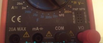
At the bottom of the instrument panel you can see several connectors:
- “COM” - common, grounded (for black probe);
- “VΩmA” - a connector that allows you to ring the contacts, measure the current strength and frequency (for the red probe);
- “10 A” is a socket for a wire that allows you to measure current up to 10A.
The fourth “°C mA Lx” socket, present on some models, measures additional parameters (temperature, gain and capacitance).
Also on the front panel you can see a rotary disk surrounded by a scale with digital values and marks. Using this dial, you can set the required values, configure them to the desired modes or perform certain functions.
Functionality check
You will need a tester to check. A modern tester is a digital multimeter that has a position on its operating mode switch for testing diodes. It is marked with a diode symbol. For pointer testers, the switch must be set to the 1 kOhm position. Make sure the battery in the tester is in good condition before taking measurements. The test being performed is impossible without a power source, such as the tester’s battery.
Checking with a multimeter
The figure shows checking the positive bus diodes. The bridge in the figure is used from a four-phase generator, but this does not change the principle of testing. The red wire is connected to the V terminal of the multimeter, and the black wire is connected to the COM terminal. Connect the red wire to the bus using an alligator clip. Using a black wire with a probe, we will begin to check the diodes of the positive bus, connecting to their anodes. We already know which diodes to check from the device description. Those whose bodies are pressed into the upper tire. What should the device show for everyone? Possible options in the table below:
Then we connect the black wire to the crocodile, and use the red probe to check the anodes. This time, serviceable diodes will be locked by the reverse voltage of the device, and the readings will be exactly the same as in the first line of the table, that is, for this connection the diode will be “broken”.
The negative bus diodes are checked in a similar way. You just need to change the connections accordingly: we start by connecting the black wire to the bus, and then move on to the red one.
If at least one device is torn or punctured, or at least gives low readings in both directions, it is faulty and needs to be replaced.
How to Accurately Test a Diode Assembly: Detailed Analysis
To check, you will need a multimeter that has a diode test mode.
Verification steps:
- Testing begins with diodes 1 and 2. To do this, the red probe of the tester is connected to the terminal with the “-” sign. Above the two center terminals there is an AC or ̴ marking. The black probe is connected in turn, first to one such terminal, and then to the second. This is a direct connection in which current flows freely. The display of the digital multimeter will show the voltage drop across the pn junction when connected directly. In foreign datasheets this value is designated as Vf. For silicon diodes it is in the range of 0.4-0.7 V. For Schottky semiconductors it is lower and equal to approximately 0.3 V. If these values are displayed on the measuring device, then the diode assembly is working.
- To clarify the results of checking diodes 1 and 2, a reverse connection is made. To do this, connect a black probe (negative) to the “-” terminal. The red probe is alternately connected to the terminals marked AC or ̴. The display should show a unit, indicating high resistance and no reverse current. If this is so, then the serviceability of diodes 1 and 2 is confirmed.
- Next, check the verification of diodes 3 and 4 under the condition of direct connection. To do this, connect the black probe to the positive, and the red one in turn is connected to the AC terminals. The display should display the voltage drop across the pn junction, which was described in detail in the first paragraph.
- To confirm the result, connect the red probe to the plus, and the black probe to the AC terminals. The display should show one.
If the diode assembly successfully passes this test, we can say with confidence that all elements are in good working order.
How to check without dismantling
You can diagnose the device on site without disassembling the generator or desoldering the part. To do this, unscrew all the wires on the generator and voltage regulator, set the tester to ohmmeter mode, and connect the lamp to the battery in the manner described above.
This method allows you to check the serviceability of the entire bridge and individual groups.
Short circuit
For this test, the positive electrode is applied to output 30 of the generator (“plus” of the power rectifier), and the negative electrode is applied to the housing. A resistance value of 1 indicates that the bridge is in good condition.
One end of the lamp is connected to the negative terminal of the generator, the other to the positive terminal. A lit lamp indicates a short circuit.
Negative group
The negative electrode of the tester is connected to the frame of the generator, the positive electrode is connected to one of the diode bridge mounting bolts. The negative group is operational if the resistance is infinity.
To check with a lamp, connect its minus to the generator casing, and the plus to the axle mounting bolt. The lamp lights up or flashes when there is a malfunction in the negative group of elements.
Positive
The positive probe of the multimeter is connected to the positive terminal, the negative one to the bridge mounting bolt. With a working group, the resistance is infinite.
The negative of the lamp is connected to the bridge mounting bolt, the plus is applied to the positive terminal. A lit lamp indicates a short circuit in the positive semiconductors.
Minor group
The positive electrode of the tester is pressed to terminal 61 (usually the “plus” of the additional rectifier), the negative electrode is connected to any bridge mounting bolt. The diodes are serviceable with a resistance value of 1.
The negative end of the lamp is connected to the bridge mounting bolt, and the positive end is connected to terminal 61. A lit lamp indicates a malfunction in this group.
Bridges can be made of individual diodes or made as a monolithic structure (diode assembly)
What you need to know about diode bridges
First, we will look at what they are and what is inside a diode bridge. These circuit elements are available in two versions:
- From discrete (separate) diodes. Usually soldered on the board and connected by tracks in the correct circuit.
- Diode assemblies. The assemblies can be either single-phase bridges for rectifying both half-cycles of alternating voltage, or assemblies of two diodes connected in a circuit by a common cathode or anode, and other connection options.
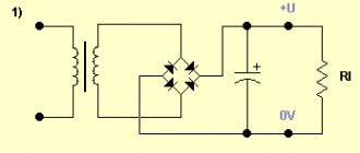
In any case, the rectifier single-phase diode bridge consists of four semiconductor diodes connected to each other in a series-parallel manner. Alternating voltage is supplied to two points at which the anode and cathode are connected (opposite poles of the diodes). Constant voltage is removed from the connection points of like poles: plus from the cathodes, minus from the anodes.
In the diagram, the connection point for alternating voltage is indicated by the symbols AC or “~”, and the outputs with constant voltage are “+” and “-“. Draw this diagram for yourself, it will be useful to us when checking.
If you imagine a real diode bridge and combine it with this circuit, you get something like:
This is interesting: Which HB4 lamps are better to put in a car
Checking with a light bulb
To implement this method, you need a 12-volt low-power light bulb and three wires 1 meter long. Two of them are used to form the indicator cord. To do this, they are first connected to the contacts of the light bulb, which as a result ends up in their gap. The third wire connects one of the battery contacts to the bridge.
To check the circuit, the bridge body is connected to the battery negative with a third wire. Then one end of the indicator cord is connected to the negative terminal of the bridge, and the other end is connected to pin 30 of the bridge. The light coming on is a sign of a breakdown of the bridge, and its absence indicates a break.
To check the negative diodes, the minus voltage of the battery is applied to the bridge body. The plus of the battery is connected with an indicator cord to the fixing screw of the bridge. If the lamp lights up, it indicates a breakdown; its absence indicates a break. Testing positive diodes begins by applying the battery positive to terminal 30, and the negative is connected through the indicator cord to the bridge mounting screw. If the diodes are working properly, the lamp does not light up.
Something else useful for you:
Diode bridge of the VAZ 2114 generator: check, replacement and repair
The diode bridge (rectifier) is one of the key components of the VAZ 2114 generator. The failure of this unit makes it impossible for the generator to function normally, and also threatens the risk of breakdown of all electronic systems of the car, so owners of the fourteenth should regularly check its condition.
Generator diode bridge
From this article you will learn why a diode bridge is needed, what design features it has, possible causes of bridge problems and methods for identifying them. Studying theoretical material will give you the opportunity to replace the unit at home, without having to spend money on the services of specialists at a service station.
Functional purpose and features of the rectifier
The diode bridge of the generator, depending on the type, can consist of either 4 or 6 diodes that perform the function of converting alternating current into direct current with a given pulsation frequency. The operating principle of the device is based on the bipolar rectification method, which is also widely used in a variety of electronic systems.
In addition to the conversion, the unit acts as a valve, the purpose of which is to pass current exclusively in one direction. With a properly functioning device, the current from the generator enters the fourteenth power network, but does not pass back to the stator. If the node fails, current leaks and flows in both directions. This will cause a constant lack of power, and the vehicle's systems that consume electricity will not be able to operate.
The VAZ 2114 is equipped with a three-phase rectifier, which has the following advantages:
- Converts alternating current into direct current with the lowest pulsation frequency: the lower the frequency, the more stable the vehicle’s electronic systems will function;
- Can be equipped with diodes of both bridge and half-bridge types;
- Makes it possible to install a current filter - a capacitor.
The cost of a diode bridge ranges from 500 to 1100 rubles, depending on the manufacturer. The market offers rectifiers both from Chinese companies, which have a low cost and questionable quality, and from well-known brands, the reliability of their products has been tested by many car owners.
As evidenced by reviews from the owners of the fourteenth, devices from LG have proven themselves to be the best. The best option in terms of price-quality ratio is the LG 0108 model. It can also be used as a diode bridge for a VAZ 2115 generator.
Components of the generator, number 9 – rectifier
Checking the diode bridge
A typical failure of the unit is the failure of the diodes due to burnout. The following reasons for this malfunction can be identified:
- Moisture, oil, dirt or dust getting on the diodes;
- Working out the operational resource.
There are several ways to inspect the generator diode bridge on a VAZ 2114, and the simplest of them is checking with a light bulb and does not require dismantling the device, but in order to repair the diode bridge or replace it, the rectifier will have to be removed.
Method No. 1: checking with a control (12 V light bulb)
- We connect the rectifier plate to the battery (terminal “-”) so that it fits tightly to the ground of both devices.
- Using a 12-volt light bulb, we connect one of its wires to the “+” terminal on the battery, and the second to the terminal of additional diodes. Next, we transfer the wiring from the “+” terminal to the bolt, which is located in the area of the rectifier stator winding.
Neither in the first nor in the second case should the contacts be closed - if the control lights up or blinks, it means the unit is faulty.
Method No. 2: examining the rectifier for broken contacts
- We connect the negative wire of the control lamp to the “+” terminal of the battery;
- We connect the plus control to the “-” terminal of the battery.
- Now we check the same places as indicated in the second paragraph of the previous algorithm.
Here, on the contrary, the light should be on. The absence of light or periodic blinking indicates a break in the rectifier stator winding.
Method number 3: checking the rectifier using a multimeter
Testing the device with a multimeter involves removing the rectifier from the generator housing. You can find out how this is done in the next section of the article.
How to repair a diode bridge?
Before repairing the generator rectifier, preparation and a general check of the performance of the diodes should be carried out. The mechanism is checked in several stages:
- Disconnecting the voltage regulators and protective casing from the bridge.
- Check for short circuit using the battery and an incandescent lamp (in case of damage to the diodes, a short circuit occurs when an incandescent lamp is connected to the terminal of the battery and the generator housing).
- Checking the condition of positive and negative elements (by connecting the plus and minus terminals of the battery and generator).
- Checking the diode bridge circuit.
- Repair or replacement of non-working elements.
Since the generator diode bridge has a low cost, every car enthusiast can repair the equipment. However, manual repairs will take a lot of time, and in order not to waste extra hours searching for information on the Internet, we suggest drivers adhere to the following recommendations:
- During the repair process, you will still have to remove the diode bridge assembly.
- The constant ingress of water into the unit causes its increased wear resistance, so it is advisable to move the rectifier to another place - less susceptible to moisture ingress. Experienced experts advise protecting the on-board network with a reliable housing under the hood.
- Pressing and unpressing the rectifier yourself will be more expensive than at a service station, but the car owner will be confident in its reliability.
- Buying diodes on the spontaneous market will be cheaper, but there is a risk of parts malfunctioning.
- Before replacing the rectifier, it is necessary to remove the insulator and the old fastener element, and be sure to transfer them to the new diode bridge.
If you want to upgrade the rectifier and install three levels of a generator relay, buy three more pairs of diode bridges that will create an independent “plus”.
Important! Checking the serviceability of parts purchased on the market is quite simple: if the “ringing” of the diode in a cold state shows from 500 to 800 Ohms, and when the engine starts, a thermal “breakdown” occurs, the design is faulty.
How to check a car generator? 5 ways to test with a multimeter
This method is one way to test your alternator without a car. Diagnostics requires access to the battery and the device itself.
For what reason can a generator fail?
The voltmeter is used in measurement mode and is connected to the common ground and the B+ terminal of the battery. When a special device is turned on in its window, the indicator should not exceed 0.5 mA.
If this value is higher, it means the diodes are faulty or the integrity of the winding insulation is damaged. This check must only be carried out with the motor connected. This method is quite problematic and requires a lot of time and accuracy. The essence of diagnostics is to measure the current strength of devices that consume electricity. The engine must be running and the speed must be as high as possible
The probe is connected to the wire going to terminal 30 or B+. Turn on all electrical devices in the car one by one and pay attention to the multimeter readings. After receiving the results, add the numbers. Then turn on all electrical appliances and compare the readings of the measuring instruments with the sum of the previous tests.
It is normal if the index is 5 A less than the amount received, but an increased value indicates a faulty part.
Check Features
The engine must be running at maximum speed. The multimeter is connected to pin 67. The device will immediately show the result and the value of the excitation current. During normal operation of the generator, this value is in the range of 3-7 A.
- The condition of the winding can be checked not only visually, but also using special instruments. The manipulation consists of carrying out preparatory work:
- dismantling the brush holder;
- dismantling the voltage regulator;
- removing slip rings;
Make sure the winding is not damaged.
After completing the preparatory work, you will need an ohmmeter. The device spindles are attached to the slip rings and stator, and then tested. Normal values are between 5 and 10 ohms.
The generator is diagnosed in a disassembled state with an ohmmeter. The device is connected to terminal 30 and the generator housing. The part must always be clean, since even a small amount of dirt can lead to a change in the data obtained.
Using an ohmmeter, all components and parts are checked one by one, so that at the end of the diagnosis, you can make a list of damaged parts. It is quite possible to eliminate detected faults on your own. You will need a minimum set of tools, as well as a full set of spare parts.
Diode diode discord
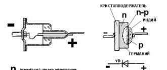
A standard diode is a component of the electrical network and acts as a pn junction semiconductor. Its structure allows current to pass through the circuit in only one direction - from the anode to the cathode (different ends of the part). To do this, you need to apply “+” to the anode and “-” to the cathode.
Note! Electric current in diodes cannot flow in the opposite direction, from the cathode to the anode.
Due to this feature of the product, if you suspect a breakdown, it can be checked with a tester or multimeter. Today there are several types of diodes in radio electronics:
Types of diodes
- Light-emitting diode. When an electric current passes through such an element, it begins to glow as a result of the transformation of energy into a visible glow;
- protective or regular diode. Such elements in the electrical network act as a suppressor or voltage limiter. One of the varieties of this element is the Schottky diode. It is also called a Schottky barrier diode. Such an element, when connected directly, gives a low voltage drop. In Schottky, instead of a pn junction, a metal-semiconductor junction is used.
If ordinary parts and LEDs are used in the vast majority of electrical appliances, then Schottky ones are used mainly in high-quality power supplies (for example, for devices such as computers). It is worth noting that testing a conventional diode and a Schottky diode is practically no different, since it is carried out according to the same principle. Therefore, there is no need to worry about this issue, because the operating principle of both Schottky and conventional diodes is identical. Note! Here it is only worth noting that Schottkis in most cases are found double, located in a common building. Moreover, they have a common cathode. In such a situation, you can not solder these parts, but check them “on the spot”.
Schottky diode
Being a component of an electronic circuit, such semiconductor elements often fail. The most common reasons for their failure are:
- exceeding the maximum permissible direct current level;
- excess reverse voltage;
- poor quality part;
- violation of the device operating rules established by the manufacturer.
Moreover, regardless of the cause of loss of performance, failure can be directly caused by either a “breakdown” or a short circuit. In any case, if there is an assumption that the electrical network has failed in the semiconductor area, it is necessary to diagnose it using a special device - a multimeter. Only to carry out such manipulations you need to know how to check the diode using it correctly.
We are looking for a diode bridge on the board
You can check both the diode bridge installed on the board and the one soldered from it; the second option is considered more accurate, since the test is not affected by other circuit elements, but it should be remembered that some testing methods can only be implemented in a working device. If the design of the device is quite complex or the board is overcrowded with parts, it is advisable to look for a diode bridge in the following locations:
- in power supplies;
- in secondary circuits of transformers;
- at the output of generators;
- in front of the batteries.
After detecting a diode bridge, it is necessary to inspect its housing or each diode individually. An experienced electrician will automatically notice the location of the inputs, but if it is difficult for you to focus on memory, you can draw a diagram in relation to your situation. On such a diagram you need to display the positive terminal and the negative terminal, the AC voltage input terminals.
It should also be noted that the malfunction may not only lie in the diode bridges, so during the inspection it is worth carefully inspecting all elements and parts, and when checking, do not exclude the integrity of the object.
A simple check of the integrity of the diode bridge of the transformer power supply
If we found out using a light bulb that there are problems on the board, using an indicator screwdriver we can find out whether there is a break on the diode bridge. If the indicator lights up on the phase wire at the input to the rectifier, we carry out further checking. If the indicator does not light up, then the problem is not in the diode circuit, but in the power cable. The indicator checks the presence of voltage at the positive output of the rectifier. If it is present, then the diode bridge is not broken. We will not receive more information during such a check.
There is no breakdown of the diode bridge