Power supplies for radio and electrical equipment almost always use rectifiers designed to convert alternating current to direct current. This is due to the fact that almost all electronic circuits and many other devices must be powered from DC sources. A rectifier can be any element with a nonlinear current-voltage characteristic, in other words, passing current differently in opposite directions. In modern devices, planar semiconductor diodes are usually used as such elements.
Planar semiconductor diodes
Along with good conductors and insulators, there are many substances that occupy an intermediate position in conductivity between these two classes. Such substances are called semiconductors. The resistance of a pure semiconductor decreases with increasing temperature, unlike metals, whose resistance increases under these conditions.
By adding a small amount of impurity to a pure semiconductor, its conductivity can be significantly changed. There are two classes of such impurities:
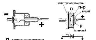
Figure 1. Planar diode: a. diode device, b. designation of a diode in electrical circuits, c. appearance of planar diodes of various powers.
The layer at the interface of p- and n-type semiconductors (pn junction) has one-way conductivity? conducts current well in one (forward) direction and very poorly in the opposite (reverse) direction. The structure of a planar diode is shown in Figure 1a. The basis ? a semiconductor plate (germanium) with a small amount of donor impurity (n-type), on which a piece of indium, which is an acceptor impurity, is placed.
Once heated, indium diffuses into the adjacent regions of the semiconductor, converting them into a p-type semiconductor. A pn junction occurs at the boundary of regions with two types of conductivity. The terminal connected to the p-type semiconductor is called the anode of the resulting diode, the opposite? its cathode. An image of a semiconductor diode on circuit diagrams is shown in Fig. 1b, appearance of planar diodes of various powers? in Fig. 1st century
Frame
It is very convenient to make the housing for the power supply from aluminum. First, a frame is assembled from corners, which is then sheathed with aluminum plates. There are at least two advantages of this solution - firstly, aluminum is easy to work with, and secondly, it conducts heat very well, which will protect the power supply from overheating.
If you don’t want to assemble the frame yourself, you can borrow it from an old microwave. This solution has certain advantages - light weight, aesthetic appearance and spaciousness.The simplest rectifier
Figure 2. Current characteristics in various circuits.
The current flowing in a conventional lighting network is variable. Its magnitude and direction change 50 times within one second. A graph of its voltage versus time is shown in Fig. 2a. Positive half-cycles are shown in red, ? negative.
Since the current value varies from zero to the maximum (amplitude) value, the concept of the effective value of current and voltage is introduced. For example, in a lighting network the effective voltage value is 220 V? in a heating device connected to this network, the same amount of heat is generated over equal periods of time as in the same device in a 220 V DC circuit.
But in fact, the network voltage changes in 0.02 s as follows:
- the first quarter of this time (period)? increases from 0 to 311 V,
- second quarter of the period? decreases from 311 V to 0,
- third quarter of the period? decreases from 0 to 311 V,
- last quarter of the period? increases from 311 V to 0.
In this case, 311 V? voltage amplitude Uо. The amplitude and effective (U) voltages are related to each other by the formula:
When a series-connected diode (VD) and load are connected to an alternating current circuit (Fig. 2b), current flows through it only during positive half-cycles (Fig. 2c). This happens due to the one-way conductivity of the diode. Is such a rectifier called half-wave? During one half of the period there is current in the circuit, during the second? absent.
The current flowing through the load in such a rectifier is not constant, but pulsating. You can turn it almost constant by connecting a filter capacitor Cf of a sufficiently large capacity in parallel with the load. During the first quarter of the period, the capacitor is charged to the amplitude value, and in the intervals between pulsations it is discharged to the load. The tension becomes almost constant. The greater the capacitor capacity, the stronger the smoothing effect.
Charger protection circuit
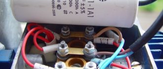
The simplest protection system can be implemented using several radio elements. Relay with a contact current exceeding the charging current (for example 16 A) - a 5-9 V DC coil. Diode - 1 A, resistor R - 5 times greater than the resistance of the relay coil. Capacitor C - for example 220 uF 25 V. Of course, the circuit has a drawback - after disconnecting the battery, the relay continues to work until the power supply is turned off.
There are two solutions you can use. First install an additional rectifier diode in the opposite direction to the "zener diode" in the relay coil circuit. The second solution is to put a rectifier diode in the opposite direction instead of the "zener diode" and an LED in the opposite direction plus a resistor and use it as a sign for the reverse connection of the battery.
I also recommend using Schottky diodes, for example, from a computer power supply. These diodes generate less heat than conventional ones. Further reduction of power losses in the rectifier can be achieved by using a transformer with a symmetrical (double) secondary winding. The transformer here is 50 watts, you can't expect much from it, but it still does its job for a long time.
Diode bridge circuit
More advanced is the full-wave rectification circuit, when both positive and negative half-cycles are used. There are several varieties of such schemes, but the most commonly used is pavement. The diode bridge circuit is shown in Fig. 3c. The red line on it shows how current flows through the load during positive times, and the blue line? negative half-cycles.
Figure 4. 12 volt rectifier circuit using a diode bridge.
In both the first and second half of the period, the current through the load flows in the same direction (Fig. 3b). The amount of pulsation within one second is not 50, as with half-wave rectification, but 100. Accordingly, with the same filter capacitor capacity, the smoothing effect will be more pronounced.
As you can see, to build a diode bridge you need 4 diodes? VD1-VD4. Previously, diode bridges on circuit diagrams were depicted exactly as in Fig. 3c. The image shown in Fig. 1 is now generally accepted. 3g. Although there is only one picture of a diode, it should not be forgotten that the bridge consists of four diodes.
The bridge circuit is most often assembled from individual diodes, but sometimes monolithic diode assemblies are also used. They are easier to mount on the board, but if one arm of the bridge fails, the entire assembly is replaced. The diodes from which the bridge is mounted are selected based on the amount of current flowing through them and the amount of permissible reverse voltage. This data can be obtained from diode instructions or reference books.
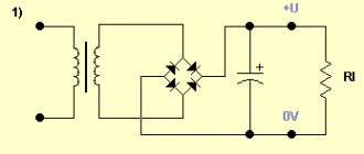
The complete circuit of a 12 volt rectifier using a diode bridge is shown in Fig. 4. T1? step-down transformer, the secondary winding of which provides a voltage of 10-12 V. Fuse FU1? This is a useful detail from a safety point of view and should not be neglected. The brand of diodes VD1-VD4, as already mentioned, is determined by the amount of current that will be consumed from the rectifier. Capacitor C1? electrolytic, with a capacity of 1000.0 μF or higher for a voltage of at least 16 V.
Output voltage? fixed, its value depends on the load. The higher the current, the lower the voltage. To obtain a regulated and stable output voltage, a more complex circuit is required. Obtain the regulated voltage from the circuit shown in Fig. 4 can be done in two ways:
It is hoped that the descriptions and diagrams given above will provide practical assistance in assembling a simple rectifier for practical needs.
There is an inconsistency in electrical engineering. On the one hand, it is more convenient to transmit energy over long distances if it is in the form of alternating voltage. On the other hand, direct current is required to power smartphones, LEDs in light bulbs, circuit boards in TVs and similar household appliances. This problem is successfully solved by a family of radio components such as rectifier diodes.
Power supply 12V 5A on an integrated circuit LM338
The voltage from the network is supplied to the step-down transformer through the 7A fuse FU1. V1 at 240 volts, is used to protect the power supply circuit from voltage surges in the electrical network. Step-down transformer Tr1 with a voltage on the secondary winding of at least 15 volts and a load current of at least 5 amperes.
The reduced voltage from the secondary winding is supplied to a diode bridge consisting of four rectifier diodes VD1-VD4. At the output of the diode bridge, an electrolytic capacitor C1 is installed, designed to smooth out the ripples of the rectified voltage. Diodes VD5 and VD6 are used as protection devices to prevent capacitors C2 and C3 from discharging from minor leakage current in the LM338 regulator. Capacitor C4 is used to filter the high-frequency component of the power supply.
For normal operation of the 12V power supply, the LM338 voltage stabilizer must be installed on the radiator. Instead of rectifier diodes VD1-VD4, you can use a rectifier assembly with a current of at least 5 amperes, for example, KBU810.
What are diodes
A diode is a semiconductor element based on a silicon crystal. Previously, these parts were also made of germanium, but over time this material was forced out due to its shortcomings. The electrical diode functions as a valve, i.e. it allows current to flow in one direction and blocks it in the other. Such capabilities are built into this part at the level of the atomic structure of its semiconductor crystals.
Read also: How to create a rack-and-pinion wood splitter with your own hands, drawing and instructions
One diode cannot obtain a full constant voltage from an alternating voltage. Therefore, in practice, more complex combinations of these elements are used. An assembly of 4 or 6 parts, combined according to a special circuit, forms a diode bridge. He is already quite capable of coping with full current rectification.
Interesting. Diodes have parasitic sensitivity to temperature and light. Transparent rectifiers in a glass case can be used as light sensors. Germanium diodes (approx. D9B) are suitable as a temperature-sensitive element. Actually, due to the strong dependence of the properties of these elements on temperature, they stopped producing them.
Single-phase and three-phase diode bridge
There are two main types of straightening assemblies:
- Single-phase bridge. Most often used in household electrical appliances. Has 4 outputs. Two of them are supplied with alternating voltage, i.e. phase (L) and zero (N). The permanent one is removed from the remaining two, i.e. plus (+) and minus (-).
- Three-phase bridge. It is found in powerful industrial installations and equipment powered by a 380 volt network. Three phases are supplied to its input (L1, L2, L3). The constant voltage is also removed from the output. Such bridges are distinguished by their large size and impressive currents that they are capable of passing through themselves.
Operating principle of a diode bridge
You can understand how a bridge performs its task by understanding how a separate diode behaves. Initially there are only two wires with alternating voltage (L and N). It has the shape of a sinusoid (Fig. a). If you add one diode to the circuit, then it will transmit only the positive half-wave (Fig. b), if this component is deployed, then the negative component (Fig. c). This voltage will no longer be variable. However, it is not suitable for powering serious electrical appliances. There are moments in it when there is no current at all. The use of four diodes will allow you to obtain a constant voltage without any interruptions (Fig. d). Three-phase bridges are straightened using the same method. However, they do this with three sine waves at the same time.
Rectifier
The voltage obtained after the diode bridge has the shape of a sinusoid, in which the negative component is reflected relative to the time axis. In simple terms, it is shaped like hills and is called pulsating. This voltage is positive. Does not contain moments when current does not flow. But it is still unstable. For example, at point “a” it is early 0 volts, and at “b” it has a maximum value. This rectifier cannot be considered complete.
To solve this problem, a smoothing electrolytic capacitor is required. On the board it is usually located in the same place as the diode assembly. The capacitance accumulates energy at those moments when it has peak values (point b), and releases it at moments of dips (a). The output is a straight line - full-fledged direct current, suitable for powering subsequent electronic components, processors, microcircuits, etc.
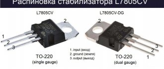
DIY power supply for 78 L 05, 78 L 12, 79 L 05, 79 L 08
Often it is necessary to power only one or a pair of microcircuits or low-power transistors. In this case, it is not rational to use a powerful power supply. Therefore, the best option would be to use stabilizers of the 78L05, 78L12, 79L05, 79L08, etc. series. They are designed for a maximum current of 100 mA = 0.1 A, but are very compact and no larger in size than a regular transistor, and also do not require installation on a radiator.
The markings and connection diagram are similar to the LM series discussed above, only the location of the pins differs.
For example, the connection diagram for the 78L05 stabilizer is shown. It is also suitable for LM7805.
The connection diagram for negative voltage stabilizers is shown below. The input is -8 V, and the output is -5 V.
As you can see, making a power supply with your own hands is very simple. Any voltage can be obtained by installing an appropriate stabilizer. You should also remember the transformer parameters. Next we will look at how to make a power supply with voltage regulation.
This powerful 12 volt power supply circuit produces a load current of up to 5 amperes. The power supply circuit uses three pins.
Brief characteristics of Lm338:
- Uinput: from 3 to 35 V.
- Uoutput: from 1.2 to 32 V.
- Iout: 5 A (max)
- Operating temperature: from 0 to 125 degrees. C
Disadvantages of a full bridge
A full-fledged full-wave bridge has disadvantages:
- The current is forced to flow not through one diode, but through two at once, connected in series. Therefore, the voltage drop across the rectifier element doubles. For low-power bridges on silicon diodes it can reach 2 volts. In powerful rectifiers - about 10 V. Hence, significant power losses on the rectifying element and its increased heating.
- If one or four diodes fail, the bridge continues to operate. This defect may not be noticeable without special measurements. However, it creates the risk of more serious damage to the device, which is powered through a faulty bridge.
How to correctly calculate the number of turns
When rewinding the secondary coil, you need to know what voltage the turn corresponds to. If you do not plan to rewind the primary winding, there is no need to calculate either the cross-section of the wire or its properties. The problem with the primary winding is the large number of turns of thin wire that make it up.
To calculate the secondary winding, make 10 turns and connect the transformer to the network. Measure the voltage at the terminals, then divide it by 10, after which 12 is divided by the resulting number. The result will be the required number of turns, and it is recommended to increase it by 10% to compensate for the voltage drop.
Design
The circuit of any rectifier bridge includes diodes. They can be separately soldered onto a printed circuit board or located in the same housing. Regarding the size, rectifiers are miniature, for example, imported MB6S or Soviet KTs405A. The latter are popularly called “ka-tseshki” or “chocolates”.
There are samples with impressive dimensions. For example, a three-phase rectifier bridge made in China. The device is designed for currents of hundreds of amperes, therefore it has screw fastening for power wires and a flat metal heat-conducting surface with holes for fixing on the cooling radiator.
Installation of elements
At the end of etching, the board is rinsed, the protection is removed from the tracks and degreased. Using a very thin drill, holes are drilled in the board for the elements. Then the elements are inserted into the holes and soldered to the tracks, after which the tracks are tinned with tin.
Rectifier markings
There are no generally accepted rules according to which manufacturers label their diode bridges. Everyone has the right to name their product as they see fit, i.e. according to its own nomenclature.
However, most of these parts have similar features that help visually determine the purpose of their pins. In the photo of a three-phase bridge (see above), the alternating current symbol is highlighted separately - a wavy line. It indicates that a sinusoidal input voltage is connected to this pin. Also on some bridge models, the input terminals are marked with the letters AC (Alternative Current), indicating alternating current. In this case, the output contacts from which direct current is removed are indicated by the symbols DC (Direct Current) or the traditional “+” and “-”. Additionally, on some rectifiers, one of the corners is “filed” on the plus side. An extended pin can also indicate “+”. This type of marking is common to many electronic components and is called a key.
Transformer
The transformer consists of a core made of a ferromagnetic material, as well as primary and secondary windings. 220 volts comes to the primary winding, and in this case, 12 are removed from the secondary winding, going to the rectifier. The cores in this type of power supply are mostly made in W- and U-shapes.
The arrangement of the windings is allowed either one on top of the other on a common coil, or separately. For example, a U-shaped core has a pair of coils, each of which has half of the windings wound on it. When connecting a transformer, the terminals are connected in series.
DIY diode bridge
To assemble the rectifier yourself, you will need 4 diodes of the same type. At the same time, they must be suitable in terms of reverse voltage, maximum current and operating frequency. Connections must be made in accordance with the diagram below. A positive voltage is removed between the two cathodes and a negative voltage between the anodes. An alternating voltage source is connected to the points at which opposite terminals of the diodes are connected. The entire circuit can be soldered by surface mounting in a couple of minutes, or you can work hard and make it in the form of a small printed circuit board.
Additional Information. The reverse voltages of diodes connected in a series circuit are added to each other.
Selecting a build type
For each task there is its own optimal version of the rectifier diode assembly. All of them can be divided into 3 types:
- Rectifier with one diode. It is used in the simplest and cheapest circuits where there is no c.l. requirements for the quality of the output voltage, as, for example, in night lights.
- Dual diode. These parts look similar to transistors, because they are produced in the same packages. They also have 3 pins. Essentially, these are two diodes placed in one housing. One of the conclusions is average. It can be the common cathode or the anode of the internal diodes.
- Full diode bridge. 4 parts in one case. Suitable for devices with high currents. It is mainly used on the inputs and outputs of various power supplies and chargers.
Additional Information. Rectifiers are also used in cars. They are needed to convert the alternating voltage coming from the generator to direct voltage. This, in turn, is necessary to charge the battery. A conventional gas generator produces alternating current.
Read also: Garden planter in the form of a stump
Selecting diodes and making a rectifier
Diodes in the rectifier are selected according to three parameters:
- highest permissible forward voltage;
- highest reverse voltage;
- highest operating current.
According to the first two parameters, 90 percent of available semiconductor devices are suitable for operation in a 12-volt circuit; the choice is mainly made based on the maximum long-term permissible current. The design of the diode body and the method of manufacturing the rectifier also depend on this parameter.
If the load current does not exceed 1 A, you can use foreign and domestic one-ampere diodes:
- 1N4001-1N4007;
- HER101-HER108;
- KD258 (“droplet”);
- KD212 and others.
KD105 (KD106) devices are designed for lower currents (up to 0.3 A). All of the listed diodes can be mounted either vertically or horizontally on a printed circuit board or circuit board, or simply on pins. They don't need radiators.
Diode bridge made of low-power elements.
If large operating currents are needed, then other diodes must be used (KD213, KD202, KD203, etc.). These devices are designed for operation on heat sinks; without them they will withstand no more than 10% of the maximum rated current. Therefore, you need to select ready-made heat sinks or make them yourself from copper or aluminum.
Another diode bridge design.
It is also convenient to use ready-made bridge diode assemblies KTs405, KVRS or similar. There is no need to assemble them - just apply an alternating voltage to the corresponding terminals and remove the constant one.
Assembly of KVRS3510.
Checking elements
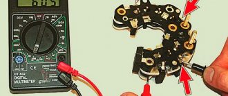
In most cases, it is not necessary to unsolder the bridge from the board for testing. It should be tested in the same way as a 4 pn junction with a diode bridge connection. This measurement is so common that its capability is implemented in any multimeter. The test device must be switched to diode continuity mode.
The forward voltage drop across a working rectifier diode is 500-700 mV. Otherwise, the device will display “1”. A burnt part most often shows “0” in both directions, i.e. short circuit. Less often, a complete breakage of the element occurs (also in both directions). All measurements should be repeated for each diode included in the bridge. Total 8 measurements, i.e. 4 in forward direction and 4 in reverse. If a Schottky diode is tested, then this parameter is 200-400 mV.
Using the Schottky barrier
The use of a Schottky diode is justified in two cases. Firstly, when you need to rectify high-frequency current. The Schottky barrier is ideal for such a task, because it has a low junction capacitance and, accordingly, is fast-acting. Secondly, when it is necessary to rectify a large current of tens or hundreds of amperes. In this case, the part performs well due to the low voltage drop and low heat generation.
Diode bridges in the world of electronics play the role of a matching element. With their help, you can connect devices that require direct current to a network of alternating voltage convenient for transmission. There are a lot of such devices in everyday life; they are extremely important for a person’s comfortable life.
The main element used to create a rectifier unit is a diode. Its operation is based on the electron-hole transition (pn).
The generally accepted definition says: a pn junction is a region of space located at the boundary of the junction of two semiconductors of different types. In this space, an n-type to p-type transition is formed. The value of conductivity depends on the atomic structure of the material, namely on how tightly the atoms hold electrons. Atoms in semiconductors are arranged in a lattice, and electrons are bound to them by electrochemical forces. This material itself is a dielectric. It either conducts current poorly or does not conduct it at all. But if atoms of certain elements are added to the lattice (doping), the physical properties of such a material change radically.
Mixed atoms begin to form, depending on their nature, free electrons or holes. The resulting excess electrons form a negative charge, and the holes form a positive charge.
An excess charge of one sign causes carriers to repel each other, while an area with an opposite charge tends to attract them towards itself. An electron, moving, occupies a free space, a hole. At the same time, a hole also forms in its old place. As a result, two flows of charge movement are created: one main and the other reverse. A material with a negative charge uses electrons as majority carriers and is called an n-type semiconductor, while a material with a positive charge using holes is called a p-type semiconductor. In both types of semiconductors, minority charges generate a current opposite to the movement of the main charges.
In radio electronics, germanium and silicon are used from materials to create pn junctions. When crystals of these substances are doped, a semiconductor with different conductivity is formed. For example, the introduction of boron leads to the appearance of free holes and the formation of p-type conductivity. Adding phosphorus, on the other hand, will create electrons and the semiconductor will become n-type.
Diode operating principle
A diode is a semiconductor device that has low resistance to current in one direction and prevents it from flowing in the opposite direction. Physically, the diode consists of one pn junction. Structurally, it is an element containing two outputs. The terminal connected to the p-region is called the anode, and the terminal connected to the n-region is called the cathode.
When a diode operates, there are three states:
A forward potential is a signal when the positive pole of the power source is connected to the p-type region of the semiconductor, in other words, the polarity of the external voltage coincides with the polarity of the main carriers. With reverse potential, the negative pole is connected to the p-region and the positive pole to the n region.
There is a potential barrier in the area where the n- and p-type material joins. It is formed by a contact potential difference and is in a balanced state. The height of the barrier does not exceed tenths of a volt and prevents the movement of charge carriers deep into the material.
If direct voltage is connected to the device, then the magnitude of the potential barrier decreases and it practically does not resist the flow of current. Its value increases and depends only on the resistance of the p- and n-regions. When a reverse potential is applied, the barrier value increases, since electrons leave the n-region and holes leave the p-region. The layers become depleted and the barrier's resistance to the passage of current increases.
The main indicator of an element is the current-voltage characteristic. It shows the relationship between the potential applied to it and the current flowing through it. This characteristic is presented in the form of a graph, which indicates the forward and reverse current.
It’s also important to know: 3 nuances about operation
The homemade product differs somewhat in its method of operation from the factory version. This is explained by the fact that the purchased unit has built-in functions that help with operation. They are difficult to install on a device assembled at home, and therefore you will have to adhere to several rules during operation.
- A self-assembled charger will not turn off when the battery is fully charged. That is why it is necessary to periodically monitor the equipment and connect a multimeter to it to monitor the charge.
- You need to be very careful not to confuse “plus” and “minus”, otherwise the charger will burn out.
- The equipment must be turned off when connecting to the charger.
By following these simple rules, you will be able to properly recharge the battery and avoid unpleasant consequences.
Simple rectifier circuit
Sinusoidal voltage is a periodic signal that varies over time. From a mathematical point of view, it is described by a function in which the origin corresponds to time equal to zero. The signal consists of two half-waves. The half-wave located in the upper part of the coordinates relative to zero is called a positive half-cycle, and in the lower part - negative.
When an alternating voltage is applied to the diode through a load connected to its terminals, current begins to flow. This current is due to the fact that at the moment the positive half-cycle of the input signal arrives, the diode opens. In this case, a positive potential is applied to the anode and a negative potential to the cathode. When the wave changes to a negative half-cycle, the diode is turned off, as the polarity of the signal at its terminals changes.
Thus, it turns out that the diode, as it were, cuts off the negative half-wave, without passing it to the load, and a pulsating current of only one polarity appears on it. Depending on the frequency of the applied voltage, and for industrial networks it is 50 Hz, the distance between the pulses also changes. This type of current is called rectified, and the process itself is called half-wave rectification.
Read also: How to make an electric scooter from a hoverboard with your own hands
By rectifying the signal using a single diode, you can power a load that does not have special requirements for voltage quality. For example, a filament. But if you power up, for example, a receiver, a low-frequency hum will appear, the source of which will be the gap that occurs between the pulses. To some extent, to get rid of the disadvantages of half-wave rectification, a capacitor connected in parallel with the load is used together with a diode. This capacitor will charge when pulses arrive and discharge when there are no pulses to the load. This means that the larger the capacitance value of the capacitor, the smoother the current across the load will be.
But the highest signal quality can be achieved if two half-waves are used simultaneously for rectification. The device that allows this to be realized is called a diode bridge, or in other words, a rectifier bridge.
Problems with a simple power supply with a load
The resistance drawn on the diagram is the equivalent of the load. The load must be such that the current supplying it, with an applied voltage of 12 V, does not exceed 1 A. You can calculate the load power and resistance using the formulas.
Where does the resistance R = 12 Ohm, and the power P = 12 watts come from? This means that if the power is more than 12 watts and the resistance is less than 12 ohms, then our circuit will begin to work with overload, will get very hot and will quickly burn out. There are several ways to solve the problem:
- Stabilize the output voltage so that when the load resistance changes, the current does not exceed the maximum permissible value or when there are sudden current surges in the load network - for example, when some devices are turned on - the peak current values are cut to the nominal value. Such phenomena occur when the power supply powers radio-electronic devices - radios, etc.
- Use special protection circuits that would turn off the power supply if the load current exceeds.
- Use more powerful power supplies or power supplies with more power reserves.
Setting the output voltage and charging current
There are two trimming resistors installed on the DC-DC converter board, one allows you to set the maximum output voltage, the other allows you to set the maximum charging current.
Plug in the charger (nothing is connected to the output wires), the indicator will show the voltage at the device output and the current is zero. Use the voltage potentiometer to set the output to 5 volts. Close the output wires together, use the current potentiometer to set the short circuit current to 6 A. Then eliminate the short circuit by disconnecting the output wires and use the voltage potentiometer to set the output to 14.5 volts.
Diode bridge
Such a device is an electrical device used to convert alternating current into direct current. The phrase “diode bridge” is formed from the word “diode”, which implies the use of diodes in it. The diode bridge rectifier circuit depends on the AC network to which it is connected. The network can be:
Depending on this, the rectifier bridge is called a Graetz bridge or a Larionov rectifier. In the first case, four diodes are used, and in the second, the device is assembled using six.
The first rectifier circuit was assembled using radio tubes and was considered a complex and expensive solution. But with the development of semiconductor technology, the diode bridge has completely replaced alternative methods of signal rectification. Selenium pillars are rarely used instead of diodes.
Device designs and characteristics
Structurally, the rectifier bridge is made of a set of individual diodes or a cast housing with four terminals. The body can be flat or cylindrical. According to the accepted standard, icons on the device body mark the terminals for connecting alternating voltage and the output constant signal. Rectifiers with a housing with a hole are designed for mounting on a radiator. The main characteristics of the rectifier bridge are:
- Highest forward voltage . This is the maximum value at which the device parameters do not go beyond the permissible limits.
- Highest permissible reverse voltage . This is the maximum pulse voltage at which the bridge operates for a long time and reliably.
- Maximum operating rectification current . Indicates the average current flowing through the bridge.
- Maximum frequency . The frequency of voltage supplied to the bridge at which the device operates efficiently and does not exceed the permissible heating.
Exceeding the rectifier's characteristics leads to a sharp reduction in its service life or breakdown of pn junctions. It should be noted that all diode parameters are indicated for an ambient temperature of 20 degrees. The disadvantages of using a bridge rectification circuit include a higher voltage drop compared to a half-wave circuit and a lower efficiency value. To reduce losses and reduce heating, bridges are often made using fast Schottky diodes.
Device connection diagram
On electrical circuits and printed circuit boards, a diode rectifier is indicated by a diode icon or in Latin letters. If the rectifier is assembled from individual diodes, then next to each is placed the designation VD and a number indicating the serial number of the diode in the circuit. VDS or BD labels are rarely used.
The diode rectifier can be connected directly to a 220 volt network or after a step-down transformer, but its connection circuit remains unchanged.
When a signal arrives in each half-cycle, current will only be able to flow through its own pair of diodes, and the opposite pair will be blocked for it. For a positive half-cycle, VD2 and VD3 will be open, and for a negative half-cycle, VD1 and VD4. As a result, the output will be a constant signal, but its pulsation frequency will be doubled. In order to reduce the ripple of the output signal, a parallel connection of capacitor C1 is used, as in the case of one diode. Such a capacitor is also called a smoothing capacitor.
But it happens that the diode bridge is placed not only in an alternating network, but is also connected to an already rectified one. Why a diode bridge is needed in such a circuit will become clear if you pay attention to which circuits use such a connection. These circuits involve the use of radioelements that are sensitive to power reversal. Using a bridge allows for simple but effective foolproof protection. In case of incorrect connection of the power polarity, the radio elements installed behind the bridge will not fail.
Functionality check
This type of electronic device can be checked without desoldering it from the circuit, since no shunting is used in the device designs. In the case of a rectifier assembled from diodes, each diode is checked separately. And in the case of a monolithic case, measurements are carried out on all four of its terminals.
The essence of the test comes down to checking the diodes for a short circuit with a multimeter. To do this, perform the following steps:
- The multimeter switches to diode or resistance vertebrae mode.
- The plug of one wire (black) is inserted into the common socket of the tester, and the second (red) into the resistance test socket.
- With the probe connected to the black wire, touch the first leg, and with the probe of the red wire, touch the third pin. The tester should show infinity, and if you change the polarity of the wires, the multimeter will show the transition resistance.
- The minus of the tester is fed to the fourth leg, and the plus to the third. The multimeter will show resistance; when changing polarity, infinity.
- Minus on the first leg, plus on the second. The tester will show an open transition, and when changing, a closed one.
Such tester readings indicate the serviceability of the rectifier. If you don't have a multimeter, you can use a regular voltmeter. But in this case you will have to supply power to the circuit and measure the voltage on the smoothing capacitor. Its value should exceed the input value by 1.4 times.
Popular posts
- DIY Easter egg for Easter 2022 - 5 best crafts 12 volt DC motor speed controller How to make a boat out of foam How to make welding pliers for spot welding How to build a horse stable Papercraft for beginners, paper modeling, 3D sculptures and simple paper figures for children How to make a bouquet in a box with your own hands: step-by-step instructions Drip irrigation in a greenhouse and in the garden with your own hands
Transformer selection
There are two ways to obtain a suitable transformer. Independent production of a step-down block and selection of a suitable one in the factory. In any case, you need to keep in mind:
- at the output of the step-down winding of the transformer, when measuring the voltage, the voltmeter will show the effective voltage (1.4 times less than the amplitude);
- on the filter capacitor without load, the constant voltage will be approximately equal to the amplitude voltage (they say that the voltage on the capacitor “rises” by 1.4 times);
- if there is no stabilizer, then under load the voltage on the capacitor will drop depending on the current;
- For the stabilizer to operate, a certain excess of the input voltage over the output voltage is required; their ratio limits the efficiency of the power supply as a whole.
From the last two points it follows that for normal operation of the power supply, the transformer voltage must exceed 12 V.