The article is worth covering the topic of how a thyristor voltage regulator performs its work, the circuit of which can be viewed in more detail on the Internet.
In everyday life, in most cases, there may be a special need to regulate the total power of household appliances, for example, electric stoves, soldering iron, boiler, as well as heating elements, in transport - engine speed and other things. In this case, a simple and amateur radio design will come to our aid - this is a special power regulator on a thyristor.
Creating such a device will not be difficult; it can become the first home-made device that will perform the function of adjusting the temperature of the tip in the soldering iron of any novice radio amateur. It should also be noted that ready-made soldering irons on a station with general temperature control and other special functions cost much more than the simplest models of soldering irons. The minimum number of parts in the design will help you assemble a simple thyristor power regulator with wall-mounted installation.
It should be noted that the mounted type of installation is an option for assembling radio-electronic components without using a special printed circuit board, and with high-quality skills, it helps to quickly assemble electronic devices with average production complexity.
You can also order an electronic type of constructor for a thyristor-type regulator, and those who want to completely understand everything on their own should study some of the circuits and the principle of operation of the device.
By the way, such a device is a total power regulator . Such a device can be used to control total power or control speed. But first you need to fully understand the general principle of operation of such a device, because this will help you understand what load you should expect when using such a regulator.
How does a thyristor do its job?
A thyristor is a controlled semiconductor device that is capable of quickly conducting current in one direction. The word controlled means a thyristor for a reason, since with its help, unlike a diode, which also conducts the total current to only one pole, you can select a separate moment when the thyristor begins the process of conducting current.
The thyristor has three current outputs at once:
- Cathode.
- Anode.
- Controlled electrode.
To allow current to flow through such a thyristor, the following conditions must be met: the part must be located on the circuit itself, which will be under general voltage, and the required short-term pulse must be applied to the control part of the electrode. Unlike a transistor, controlling such a thyristor will not require the user to hold the control signal.
But all the difficulties of using such a device will not end there: the thyristor can be easily closed by interrupting the flow of current into it through the circuit, or by creating a reverse anode-cathode voltage. This will mean that the use of a thyristor in DC circuits is considered quite specific and in most cases completely unreasonable, and in AC circuits, for example, in a device such as a thyristor regulator, the circuit is created in such a way that the condition for closing the device is fully ensured . Any given half-wave will completely cover the corresponding section of the thyristor.
is most likely difficult for you to understand the diagram of its structure . But, there is no need to be upset - the process of functioning of such a device will be described in more detail below.
General information
AC electric motors have become widespread in many areas of human activity, namely asynchronous-type models. The main purpose of the engine as an electric machine is the transformation of electrical energy into mechanical energy . Asynchronous in translation means non-simultaneous, since the rotor speed differs from the frequency of the alternating voltage (U) in the stator. There are two types of asynchronous motors based on the type of power supply:
- Single-phase.
- Three-phase.
Single-phase ones are used for household needs, and three-phase ones are used in production. Three-phase asynchronous motors (hereinafter referred to as TAM) use two types of rotors:
- closed;
- phase
Closed-circuit motors make up about 95% of all motors used and have significant power (from 250 W and above). The phase type is structurally different from AD , but is used quite rarely compared to the first. The rotor is a cylindrical steel figure that is placed inside the stator, with a core pressed onto its surface.
Squirrel cage and wound rotors
Highly conductive copper (for high-power machines) or aluminum rods (for lower-power machines) soldered or poured into the surface of the core and short-circuited at the ends with two rings play the role of electromagnets with poles facing the stator. The winding rods do not have any insulation, since the voltage in such a winding is zero.
More commonly used for mid-power motor cores, aluminum has low density and high electrical conductivity.
To reduce the higher harmonics of the electromotive force (EMF) and eliminate the pulsation of the magnetic field, the rotor rods have a specifically calculated angle of inclination relative to the axis of rotation. If a low-power electric motor is used, the grooves are closed structures that separate the rotor from the gap in order to increase the inductive component of the resistance.
The rotor in the form of a phase design or type is characterized by a winding, its ends are connected in a star type and attached to slip rings (on the shaft), along which graphite brushes slide. To eliminate eddy currents, the surface of the windings is covered with an oxide film. In addition, a resistor is added to the rotor winding circuit, which allows you to change the active resistance (R) of the rotor circuit to reduce the values of inrush currents (Ip). Starting currents negatively affect the electrical and mechanical parts of the electric motor. Variable resistors used to regulate Ip:
- Metal or stepped with manual switching.
- Liquid (due to immersion to the depth of the electrodes).
Graphite brushes are subject to wear, and some models are equipped with a squirrel-cage design that lifts the brushes and closes the rings after the motor starts. IMs with a wound rotor are more flexible in terms of regulation of Ip.
Design features
An asynchronous motor does not have pronounced poles, unlike a DC electric motor. The number of poles is determined by the number of coils in the windings of the stationary part (stator) and the method of connection. In an asynchronous machine with 4 coils, a magnetic flux passes through. The stator is made of special steel sheets (electrical steel), which reduce eddy currents to zero, at which significant heating of the windings occurs. It leads to a massive interturn short circuit.
The iron ore or rotor core is pressed directly onto the shaft. There is a minimum air gap between the rotor and stator. The rotor winding is made in the form of a “squirrel cage” and is made of copper or aluminum rods.
In electric motors with a power of up to 100 kW, aluminum, which has a low density, is used to fill the grooves of the rotor core. But despite this device, engines of this type get hot. To solve this problem, fans are used for forced cooling , which are mounted on the shaft. These engines are simple and reliable. However, motors consume a large current when starting, 7 times the rated current. Because of this, they have a low starting torque, since most of the electrical energy goes to heating the windings.
Electric motors, which have an increased starting torque, differ from ordinary asynchronous motors in the design of the rotor. The rotor is made in the form of a double “squirrel cage”. These models are similar to the phase types of rotor manufacturing. It consists of an inner and outer “squirrel cage”, and the outer one is the starting one and has a large active and small reactive R. The outer one has a slight active and high reactive R. As the rotation speed increases, I switches to the inner cage and operates in the form of a squirrel-cage rotor.
Principle of operation
When I flows through the stator winding, a magnetic flux (F) is created in each of them. These F are shifted by 120 degrees relative to each other. The resulting F is rotating, creating an electromotive force (EMF) in aluminum or copper conductors. As a result of this, a starting magnetic moment of the electric motor is created, and the rotor begins to rotate. This process is also called slip (S) in some sources, showing the frequency difference n1 of the electromagnetic field of the starter, which becomes greater than the frequency obtained when rotor n2 rotates. It is calculated as a percentage and has the form: S = ((n1-n2)/n1) * 100%.
The value of S at the initial start of the electric motor is approximately 1, but as the values increase, n2 becomes smaller. At this moment, I in the rotor decreases, therefore, the EMF becomes less than its nominal value. At idle, S is minimal, but as the moment of static interaction between the rotor and stator increases, this value reaches a critical value. If the inequality is satisfied: S > Scr, then the motor operates normally, but if the value of Scr is exceeded, it may “capsize”. Rollover causes unstable operation but disappears over time.
Area of use of thyristor devices
For what purposes can a device such as a thyristor power regulator be used? Such a device allows you to more effectively regulate the power of heating devices, that is, load the active places. When working with a highly inductive load, thyristors may simply not close, which can lead to such equipment failing to operate normally.
Is it possible to independently regulate the speed of the device’s engine?
Many of the users who have seen or even actually used drills, angle grinders, which are otherwise called grinders, and other power tools. They could easily see that the number of revolutions in such products depends mainly on the overall depth of pressing the trigger button in the device . Such an element will be located in the thyristor power regulator (the general diagram of such a device is indicated on the Internet), with the help of which the total number of revolutions changes.
It is worth paying attention to the fact that the regulator cannot independently change its speed in asynchronous motors. Thus, the voltage will be fully regulated on the commutator motor, which is equipped with a special alkaline unit.
Speed setting methods
To prevent negative influence during start-up, you need to reduce the speed of the electric motor 220 V or 380 V. There are several ways to achieve this goal:
- Changing the R value of the rotor circuit.
- Change in U in the stator winding.
- Change of frequency U.
- Switching poles.
When changing the R value of the rotor part using additional resistors, the rotation speed decreases, but as a result, the power decreases. Consequently, there is a significant loss of electricity. This type of regulation should be used for a wound rotor.
By changing the U values on the stator coil, mechanical or electrical control of the rotor speed is possible. In this case, the U regulator is used. Using this method allows it to be used only with a fan load (for example, a 220V fan speed regulator). For all other cases, three-phase automatic transformers are used, which allow smooth changes in U values, or thyristor regulators.
Based on the formula for the dependence of the rotation speed on the supply frequency U, it is possible to regulate the number of rotor revolutions. The frequency of the rotating magnetic field of the stator is calculated by the formula: Nst = 60 * f / p (f is the frequency of the supply network current, p is the number of pole pairs). This method provides the ability to smoothly control the rotation speed of the rotor part. To obtain a high efficiency, you need to change the frequency and U. This method is optimal for engines with a squirrel-cage rotor, since power losses are minimal. There are two methods for changing the number of pole pairs:
- In the stator (in the slots) you need to place 2 windings with different numbers p.
- The winding consists of two parts connected in parallel or in series.
The main disadvantage of this method is maintaining a stepwise change in the frequency of an electric motor with a squirrel-cage rotor.
How does such a device work?
The characteristics described below will correspond to most circuits.
- A thyristor total power regulator, the principle and operating features of which will be based on the phase control of the voltage value, also changes the total power in the devices. This feature lies in the fact that under normal production conditions the load can be affected by approximate voltage indicators of the household network, which will change in accordance with the sinusoidal law. Above, when describing the principle of operation of a thyristor, it was said that any thyristor includes operation in only one direction, that is, it controls its half-wave from sinusoids. What could this mean?
- If, using a device such as a thyristor, a load is connected over time at a strictly defined time, then the effective voltage indicator will be quite low, since half of the voltage (the effective value, which reproduces the load) will be much less than the light voltage. This phenomenon can be seen on motion graphs.
In this case, there is a certain area that will be under special stress. When the effect of the positive half-wave ends and a new period of movement with a negative half-wave begins, one of these thyristors will begin to close, and at the same time a new thyristor will open.
Instead of the words positive and negative wave, you should use the first and second (half-wave).
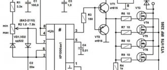
While the first half-wave begins to influence the circuit, a special charging of the capacitance C1 and also C2 occurs . The speed of their full charging will be limited by potentiometer R 5. Such an element will be completely variable, and with its help the output voltage will be set. At the moment when the voltage necessary to open diristor VS 3 appears on the surface of capacitor C1, the entire dinistor will open, and a current will begin to pass through it, with the help of which thyristor VS 1 will open.
During the breakdown of the dinistra, a point is formed on the general chart. After the voltage value passes the zero mark, and the circuit is under the influence of the second half-wave, the thyristor VS 1 will close, and the process will be repeated, only for the second dinistor, thyristor, and also the capacitor. Resistors R 3 and R 3 are needed to limit the total control current, and R 1 and R 2 are needed for the process of thermal stabilization of the entire circuit.
The principle of operation of the second circuit will be exactly the same, but it will control only one of the half-waves of alternating current. After the user understands the principle of operation of the device and its general structure, he will be able to understand how to assemble or, if necessary, repair the thyristor power regulator himself.
Triac power regulator
A triac, by and large , is a special case of a thyristor that passes current in both directions, provided that it is higher than the holding current. One of its disadvantages is its poor performance at high frequencies. Therefore, it is often used in low-frequency networks. It is quite suitable for building a power regulator based on a regular 220 V, 50 Hz network.
The voltage regulator on the triac is used in ordinary household appliances where adjustment is needed. The power regulator circuit on a triac looks like this.
- Etc. 1 - fuse (selected depending on the required power).
- R3 - current-limiting resistor - serves to ensure that when the potentiometer resistance is zero, the remaining elements do not burn out.
- R2 is a potentiometer, a trimming resistor, which is used for adjustment.
- C1 is the main capacitor, the charge of which unlocks the dinistor to a certain level; together with R2 and R3 it forms an RC circuit
- VD3 is a dinistor, the opening of which controls the triac.
- VD4 - triac - the main element that performs switching and, accordingly, adjustment.
The main work is assigned to the dinistor and triac. The mains voltage is supplied to an RC circuit in which a potentiometer is installed, which ultimately regulates the power. By adjusting the resistance, we change the charging time of the capacitor and thereby the threshold for turning on the dinistor, which, in turn, turns on the triac. An RC damper circuit connected in parallel with the triac serves to smooth out noise at the output, and also protects the triac from surges of high reverse voltage in case of a reactive load (motor or inductance).
The triac turns on when the current passing through the dynistor exceeds the holding current (reference parameter). It turns off, respectively, when the current becomes less than the holding current . Conductivity in both directions allows for smoother adjustment than is possible, for example, with a single thyristor, while using a minimum of elements.
The power adjustment oscillogram is shown below. It shows that after the triac is turned on, the remaining half-wave is supplied to the load and when it reaches 0, when the holding current decreases to such an extent that the triac turns off. In the second “negative” half-cycle, the same process occurs, since the triac has conductivity in both directions.
DIY thyristor voltage regulator
This cannot be said that this circuit will not provide galvanic isolation from the power source, so there is a certain danger of electric shock. This will mean that you do not need to touch the regulator elements with your hands.
You should design the design of your device in such a way that, if possible, you can hide it in an adjustable device , and also find more free space inside the case. If the adjustable device is located at a stationary level, then it makes some sense to connect it through a switch with a special light brightness control. Such a solution can partially protect a person from electric shock, and will also relieve him of the need to find a suitable housing for the device, has an attractive external structure, and is also created using industrial technologies.
Methods for regulating phase voltage in the network
- There are several ways to regulate alternating voltage in thyristors: you can skip or disable the output on the regulator as many as four half-cycles (or periods) of alternating voltage. It can be turned on not at the beginning of the half-cycle of the mains voltage, but with a certain delay. During this time, the voltage at the output of the regulator will be equal to zero, and the total power will not be transferred to the output of the device. During the second part of the half-cycle, the thyristor will begin to conduct current and a special input voltage will appear at the output of the regulator.
- The delay time in most cases is called the opening angle of the thyristor, since during the zero angle value almost all the voltage from the input will go to the output, only the drop in the open area of the thyristor will begin to be lost. As the total thyristor angle increases, the voltage regulator will significantly reduce the output voltage parameter.
- The regulating characteristic of such a device during its operation, during active load, is carried out especially intensively. At an angle of 90 degrees (electrical), the output from the connector will be half the input voltage, and at a total angle of 180 electrical degrees, the output will be zero.
Based on the principles and features of phase voltage regulation, it is possible to construct certain regulation, stabilization, and, in some cases, soft start schemes. To achieve a smoother start, the voltage should be increased over time from zero to the maximum value. Thus, during the opening of the thyristor, the maximum value should change to zero.
A little about cooling
For cooling, oddly enough, a cooling radiator is required.
It should be attached to the flange of the control element, and a layer of heat-conducting paste should be applied between them.
It is necessary to select the surface area of the radiator through trial and error.
From experience, I must say that if your homemade dimmer is installed on a soldering iron, incandescent lamp or other object with a power of up to 80 W, then you can do without a radiator.
If the regulator is used in a device whose controlled load power reaches 1000 W, then a radiator with an area of 200 square centimeters will be required; during long-term operation (5 hours), such a radiator heated up to 90 degrees Celsius.
Well, for long-term work with a 3 kW load, I took the same radiator, and installed an additional fan-cooler from the computer to cool the processor, which was powered by a miniature rectifier. At the same time, the radiator temperature was room temperature.
Source prom.st
I recommend the following video, in which the author independently makes a power regulator with his own hands:
Thyristor circuits
You can regulate the total power of the soldering iron quite simply if you use analog or digital soldering stations . The latter are quite expensive to use, and it is quite difficult to assemble them without much experience. While analog devices (considered to be essentially total power regulators) are not difficult to create yourself.
A fairly simple circuit of the device that will help regulate the power indicator on the soldering iron.
- VD - KD209 (or similar in its general characteristics).
- R 1 - resistance with a special rating of 15 kOhm.
- R2 is a resistor that has a special AC current rating of about 30 kOhm.
- Rn is the total load (in this case a special pendulum will be used instead).
Such a regulation device can control not only the positive half-cycle; for this reason, the power of the soldering iron will be several times less than the nominal one. Such a thyristor is controlled using a special circuit, which carries two resistances, as well as a capacitance. The charging time of the condensate (it will be regulated by a special resistance R2) affects the duration of opening of such a thyristor.
Security measures
The entire process of assembling a homemade power regulator must occur strictly according to the diagram and instructions while observing safety rules.
The dimmer operates at a high voltage of 220 volts; for safety reasons, do not touch the device with a tool, much less with your bare hands.
However, know that the flange and, accordingly, the triac does not generate current - this has been tested from personal experience.
The performance of the dimmer should be checked on incandescent lamps with a power of 60 to 80 W.
It is not recommended to connect energy-saving, LED or other lamps in which starting devices and pulse converters are included.