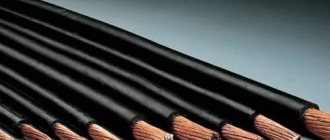
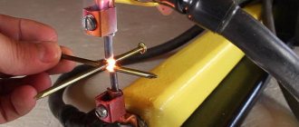
One of the main components of a truly high-quality seam is the correct and precise adjustment of the welding current in accordance with the task at hand. Experienced welders often have to work with metal of different thicknesses, and sometimes the standard min/max adjustment is not enough for proper work. In such cases, there is a need for multi-stage current regulation, accurate to the nearest ampere. This problem can be easily solved by connecting an additional device to the circuit - a current regulator.
The current can be adjusted in the secondary (secondary winding) and in the primary (primary winding). Moreover, each method of setting up a transformer for welding has its own characteristics that are important to consider. In this article we will tell you how to regulate the current in welding machines, provide diagrams of regulators for a semi-automatic welding machine, and help you choose the right welding current regulator for the primary winding for a welding transformer.
Methods for adjusting current
There are many ways to regulate the current, and above we wrote about the secondary and primary windings. In fact, this is a very rough classification, since the adjustment is still divided into several components. We will not be able to analyze all the components within the framework of this article, so we will focus on the most popular ones.
One of the most commonly used current control methods is to add a ballast at the output of the secondary winding. This is a reliable and durable method; you can easily make a ballast with your own hands and use it without additional equipment. Often, ballasts are used solely to reduce current.
In this article, we described in detail the operating principle and features of using a ballast for a semi-automatic welding machine. There you will find detailed instructions on how to make the device at home and how to use it in your work.
Despite many advantages, the method of adjusting the current through the secondary winding when used in conjunction with a welding transformer may not be very convenient, especially for novice welders. First of all, the ballast is quite bulky and its size can reach a meter in length. The device is also often underfoot and gets very hot, and this is a gross violation of safety regulations.
If you are not ready to put up with these shortcomings, then we recommend that you pay attention to the method when the welding current is adjusted through the primary winding. For these purposes, electronic devices that can be easily made with your own hands are often used. Such a device will easily regulate the current through the primary and will not cause inconvenience to the welder during operation.
The electronic regulator will become an indispensable assistant for a summer resident who is forced to weld under conditions of unstable voltage. Often houses are simply not allowed to use electrical appliances larger than 3-5 kW, and this is very limiting in their work. Using the regulator, you can configure your device so that it can operate smoothly even with low voltage. Also, such a device will be useful for craftsmen who need to constantly move from place to place while working. After all, the regulator does not need to be dragged around like a ballast, and it will never cause injury.
Now we will talk about how to make an electronic regulator from thyristors yourself.
General concepts
The principle of arc welding is well known. Let's refresh our memory of the basic concepts. To obtain a welding joint, an arc must be created. An electric arc occurs when voltage is applied between the welding electrode and the surface of the material being welded. The arc current melts the metal, forming a molten pool between the two ends. After the seam has cooled, we obtain a strong connection between the two metals.
Arc welding diagram.
In Russia, alternating current is regulated at a frequency of 50 Hz. Power for the welding machine is supplied from the mains with a phase voltage of 220 V. Welding transformers have two windings: primary and secondary. The secondary voltage of the transformer is 70 V.
Separate manual and automatic welding modes. In a home workshop, welding is carried out manually. We list the parameters that can be changed manually:
- welding current;
- arc voltage;
- welding electrode speed;
- number of passes per seam;
- diameter and brand of electrode.
The correct selection and maintenance of the necessary parameters throughout the welding process are the key to a high-quality welded joint..
When carrying out manual arc welding, it is necessary to correctly distribute the current. This will allow you to make a high-quality seam. The stability of the arc directly depends on the magnitude of the welding current. Experts select it based on the diameter of the electrodes and the thickness of the materials being welded.
Thyristor regulator circuit
Above you can see a diagram of a simple regulator using 2 thyristors with a minimum of non-scarce parts. You can also make a regulator using a triac, but our practice has shown that a thyristor power regulator is more durable and operates more stably. The assembly diagram is very simple and according to it you can quickly assemble the regulator with minimal soldering skills.
The operating principle of this regulator is also simple. We have a primary winding circuit into which the regulator is connected. The regulator consists of transistors VS1 and VS2 (for each half-wave). The RC circuit determines the moment when the thyristors open, and at the same time the resistance R7 changes. As a result, we get the opportunity to change the current in the primary of the transformer, after which the current changes in the secondary.
Note! The regulator is adjusted under voltage, do not forget about this. To avoid fatal mistakes and avoid injury, it is necessary to isolate all radio elements.
In principle, you can use old-style transistors. This is a great way to save money, since these transistors can easily be found in an old radio or at a flea market. But keep in mind that such transistors must be used at an operating voltage of at least 400 V. If you find it necessary, you can use dinistors instead of the transistors and resistors shown in the diagram. We did not use dinistors, since in this version they do not work very stably. In general, this thyristor-based welding current regulator circuit has proven itself well, and on its basis many regulators have been manufactured that operate stably and perform their function well.
You could also see in stores the resistance welding regulator RKS-801 and the resistance welding regulator RKS-15-1. We do not recommend making them yourself, since it will take a lot of time and will not save you much money, but if you want, you can make RKS-801. Below you see a diagram of the regulator and a diagram of its connection to the welder. Open the pictures in a new window to see the text better.
Welding with direct and alternating current
In the modern world, DC welding is used to a greater extent. This is due to the possibility of reducing the amount of filler material of the electrodes in the weld. But when welding with alternating voltage, you can achieve very high-quality welding results. Welding power sources operating with alternating voltage can be divided into several types:
- Instruments for argon arc welding. Special electrodes are used here that do not melt, making argon welding as comfortable as possible;
- Apparatus for the production of RDS by alternating electric current;
- Equipment for semi-automatic welding.
Alternating welding methods are divided into two types:
- use of non-consumable electrodes;
- piece electrodes.
There are two types of DC welding, reverse and direct polarity. In the second option, the welding current moves from negative to positive, and the heat is concentrated on the workpiece. And the reverse concentrates attention on the end of the electrode.
A DC welding generator consists of a motor and a current generator itself. They are used for manual welding during installation work and in the field.
Manufacturing of the regulator
To make a control device for welding current, you will need the following components:
- Resistors;
- Wire (nichrome);
- Coil;
- design or diagram of the device;
- Switch;
- Spring made of steel;
- Cable.
Welding current measurement
Once you have made and configured the regulator, it can be used in operation. To do this, you need another device that will measure the welding current. Unfortunately, it will not be possible to use household ammeters, since they are not capable of working with semi-automatic devices with a power of more than 200 amperes. Therefore, we recommend using a clamp meter. This is a relatively inexpensive and accurate way to find out the current value; the clamp control is clear and simple.
Read also: How to make a hole in the wall without a drill
The so-called “clamps” at the top of the device grip the wire and measure the current. There is a current measurement limit switch on the device body. Depending on the model and price, different manufacturers make clamp meters capable of operating in the range of 100 to 500 amps. Choose a device whose characteristics match your welding machine.
Clamp meters are an excellent choice if you need to quickly measure current without interfering with the circuit or connecting additional elements to it. But there is one drawback: clamps are absolutely useless when measuring DC current values. The fact is that direct current does not create an alternating electromagnetic field, so the device simply does not see it. But when working with alternating current, such a device meets all expectations.
There is another way to measure current, it is more radical. You can add an industrial ammeter to the circuit of your semi-automatic welding machine, capable of measuring large current values. You can also simply temporarily add an ammeter to the open circuit of the welding wires. On the left you can see a diagram of such an ammeter, according to which you can assemble it.
This is a cheap and effective way to measure current, but using an ammeter in welding machines also has its own characteristics. It is not the ammeter itself that is added to the circuit, but its resistor or shunt, and the dial indicator must be connected in parallel to the resistor or shunt. If you do not follow this sequence, the device, at best, simply will not work.
Changing the number of turns
With this method, the arc characteristics are adjusted by changing the transformation ratio. The transformation ratio can be changed by additional taps from the secondary coil. By switching from one tap to another, you can change the voltage in the output circuit of the device, which leads to a change in arc power.
The regulator must withstand high welding current. The disadvantage is the difficulty of finding a switch with such characteristics, a small range of adjustments and discreteness of the transformation ratio.
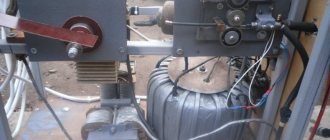
Versatile capabilities and tasks performed
A friend needed a machine for welding and cutting pipes, angles, sheets of different thicknesses with the ability to work with 3÷5 mm electrodes. Welding inverters were not known at that time.
We settled on the DC design, as it is more universal and provides high-quality seams.
Thyristors removed the negative half-wave, creating a pulsating current, but did not smooth out the peaks to an ideal state.
The welding output current control circuit allows you to adjust its value from small values for welding up to 160-200 amperes required when cutting with electrodes. She:
- made on a board from thick getinax;
- covered with a dielectric casing;
- mounted on the housing with the output of the adjusting potentiometer handle.
The weight and dimensions of the welding machine were smaller compared to the factory model. We placed it on a small cart with wheels. To change jobs, one person rolled it freely without much effort.
The power cord was connected through an extension cord to the connector of the input electrical panel, and the welding hoses were simply wound around the body.
Methods of regulation
The current can be controlled in different ways. The main methods of regulation are:
- introducing a resistive or inductive load into the secondary winding of the welding machine;
- changing the number of turns in the secondary winding;
- change in the magnetic flux of the welding machine;
- use of semiconductor devices.
There are many schematic implementations of these methods. When making a welding machine with your own hands, everyone can choose a regulator according to their taste and capabilities.
Simple design of DC welding machine
Based on the installation principle, the following parts can be distinguished:
- homemade transformer for welding;
- its power supply circuit is from network 220;
- output welding hoses;
- power unit of a thyristor current regulator with an electronic control circuit from a pulse winding.
Pulse winding III is located in power zone II and is connected through capacitor C. The amplitude and duration of the pulses depend on the ratio of the number of turns in the capacitor.
Adjustment in inverters
Welding inverters are the most modern devices for electric arc welding. The use of powerful semiconductor rectifiers at the input of the device and the subsequent transformation of alternating current into direct current, and then into high-frequency alternating current, made it possible to create devices that are compact and powerful at the same time.
In inverter devices, the main regulator is changing the frequency of the master generator. For the same transformer size, the conversion power directly depends on the frequency of the input voltage.
The lower the frequency, the less power is transferred to the secondary winding. The adjustment resistor knob is displayed on the front panel of the inverter. When it rotates, the characteristics of the master oscillator change, which leads to a change in the switching mode of the power transistors. The result is the required welding current.
When using inverter semi-automatic welding machines, the settings are the same as when using manual welding.
In addition to external regulators, the inverter control unit contains many different control elements and protections that ensure a stable arc and safe operation. For a novice welder, the best choice would be an inverter welding machine .
How to make the most convenient transformer for welding: practical tips
Theoretically, you can use any model of transformer to power the welding machine. The main requirements for it:
- provide arc ignition voltage at idle speed;
- reliably withstand the load current during welding without overheating the insulation from prolonged operation;
- meet electrical safety requirements.
In practice, I have come across different designs of homemade or factory-made transformers. However, they all require electrical engineering calculations.
I have been using a simplified technique for a long time, which allows me to create fairly reliable transformer designs of medium accuracy class. This is quite enough for household purposes and power supplies for amateur radio devices.
It is described on my website in an article about making a transformer soldering iron Moment with your own hands. This is an average technology. It does not require clarification of the grades and characteristics of electrical steel. We usually don’t know them and cannot take them into account.
Features of core manufacturing
Craftsmen make magnetic wires from electrical steel of various profiles: rectangular, toroidal, double rectangular. They even wind coils of wire around the stators of burnt-out powerful asynchronous electric motors.
We had the opportunity to use decommissioned high-voltage equipment with dismantled current and voltage transformers. They took strips of electrical steel from them and made two donut rings out of them. The cross-sectional area of each was calculated to be 47.3 cm 2 .
They were insulated with varnished cloth and secured with cotton tape, forming a figure of a reclining figure eight.
They began to wind the wire on top of the reinforced insulating layer.
Secrets of the power winding device
The wire for any circuit must have good, durable insulation, designed to withstand long-term operation when heated. Otherwise, it will simply burn during welding. We proceeded from what was at hand.
We received a wire with varnish insulation, covered with a fabric sheath on top. Its diameter - 1.71 mm is small, but the metal is copper.
Since there was simply no other wire, they began to make the power winding out of it with two parallel lines: W1 and W'1 with the same number of turns - 210.
Read also: Calculation of deposited metal during welding
The core donuts were mounted tightly: this way they have smaller dimensions and weight. However, the flow area for the winding wire is also limited. Installation is difficult. Therefore, each power half-winding was separated into its own magnetic circuit rings.
In this way we:
- doubled the cross-section of the power winding wire;
- saved space inside the donuts to accommodate the power winding.
Wire alignment
You can get a tight winding only from a well-aligned core. When we removed the wire from the old transformer, it turned out to be bent.
We figured out the required length in our minds. Of course it wasn't enough. Each winding had to be made from two parts and spliced with a screw clamp directly on the donut.
The wire was stretched along its entire length on the street. We picked up the pliers. They clamped the opposite ends and pulled with force in different directions. The vein turned out to be well aligned. They twisted it into a ring with a diameter of about a meter.
Technology of winding wire on a torus
For the power winding, we used the rim or wheel winding method, when a large-diameter ring is made of wire and wound inside the torus by rotating one turn at a time.
The same principle is used when putting a winding ring on, for example, a key or keychain. After the wheel is inserted inside the donut, they begin to gradually unwind it, laying and fixing the wire.
This process was well demonstrated by Alexey Molodetsky in his video “Winding a torus on a rim.”
This work is difficult, painstaking, and requires perseverance and attention. The wire must be laid tightly, counted, the process of filling the internal cavity must be monitored, and the number of turns wound must be recorded.
How to wind a power winding
For it, we found a copper wire of a suitable cross-section - 21 mm 2. We estimated the length. It affects the number of turns, and the no-load voltage necessary for good ignition of the electric arc depends on them.
Typically reference books recommend 60-70 volts. One experienced welder told us that in our case 50 would be enough. We decided to check it, and if it wasn’t enough, then increase the winding further.
We made 48 turns with the middle terminal. In total, there were three ends on the donut:
- middle - for direct connection of the “plus” to the welding electrode;
- the outer ones - to the thyristors and after them to ground.
Since the donuts are fastened together and the power windings are already mounted on them along the edges of the rings, the winding of the power circuit was carried out using the “shuttle” method. The aligned wire was folded like a snake and pushed through the holes of the donuts for each turn.
The middle point was unsoldered using a screw connection and insulated with varnished cloth.
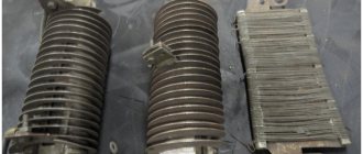
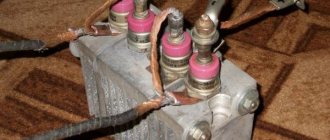
Operation of the ballast connection
The ballast resistance of the control apparatus is at the level of 0.001 Ohm. It is selected through experiment. Directly to obtain resistance, resistance wires of high power are mainly used; they are used in trolleybuses or on lifts.
You can even reduce the high frequency welding voltage by using a steel door spring.
Such resistance is turned on permanently or in another way, so that in the future it will be possible to easily adjust the indicators. One edge of this resistance is connected to the output of the transformer structure, the other is provided with a special clamping tool that can be thrown along the entire length of the spiral, which will allow you to select the desired voltage force. The main part of resistors using high-power wire is produced in the form of an open spiral. It is mounted on a structure half a meter long. Thus, the spiral is also made from heating element wire. When resistors made of a magnetic alloy are combined with a spiral or any part made of steel, in the process of passing high current, it will begin to tremble noticeably. The spiral has such dependence only until the moment it stretches.
Reliable welding current control circuit
The work involves three blocks:
- stabilized voltage;
- formation of high-frequency pulses;
- separation of pulses into circuits of thyristor control electrodes.
Voltage stabilization
An additional transformer with an output voltage of about 30 V is connected from the power winding of the 220 volt transformer. It is rectified by a diode bridge based on D226D and stabilized by two zener diodes D814V.
In principle, any power supply with similar electrical characteristics of current and output voltage can work here.
Pulse block
The stabilized voltage is smoothed by capacitor C1 and supplied to the pulse transformer through two bipolar transistors of direct and reverse polarity KT315 and KT203A.
Transistors generate pulses to the primary winding Tr2. This is a toroidal type pulse transformer. It is made of permalloy, although a ferrite ring can also be used.
Winding of three windings was carried out simultaneously with three pieces of wire with a diameter of 0.2 mm. Made 50 turns. The polarity of their inclusion matters. It is shown by dots in the diagram. The voltage on each output circuit is about 4 volts.
Windings II and III are included in the control circuit for power thyristors VS1, VS2. Their current is limited by resistors R7 and R8, and part of the harmonic is cut off by diodes VD7, VD8. We checked the appearance of the pulses with an oscilloscope.
In this chain, the resistors must be selected for the voltage of the pulse generator so that its current reliably controls the operation of each thyristor.
The unlocking current is 200 mA, and the unlocking voltage is 3.5 volts.
Welding current regulation
Variable resistor R2, with its resistance, determines the position of each pulse passed through the control electrode of the thyristor. The shape of the pulsating current at the output of the power circuit of the welding machine depends on it.
Half-sine ripples can pass through completely when the welding current is set to maximum or be cut off to almost zero.
How to make a throttle yourself?
It is quite possible to make your own throttle at home. This occurs when there is a straight coil with a sufficient number of turns of the desired cord. Inside the coil are straight metal plates from the transformer. By choosing the thickness of these plates, it is possible to select the starting reactance.
Let's look at a specific example. A choke with a coil with 400 turns and a cord with a diameter of 1.5 mm is filled with plates with a cross-section of 4.5 square centimeters. The length of the coil and wire should be the same. As a result, the 120 A transformer current will be reduced by half. Such a choke is made with a resistance that can be changed. To carry out such an operation, it is necessary to measure the deepening of the passage of the core rod into the coil. Without this tool, the coil will have little resistance, but if the rod is inserted into it, the resistance will increase to its maximum.
A choke that is wound with the correct cord will not overheat, but the core may experience strong vibration. This is taken into account when screeding and fastening iron plates.
Personal impressions of use
When the DC welding machine was made with our own hands, we began to study its capabilities. First of all, we experimented with the polarity of the electrode connection and identified a pattern.
The electrode can be supplied with “plus” - direct polarity or “minus” - reverse polarity. In this case, the depth of weld penetration changes. With reverse polarity it increases by about 40-50%.
Our welding machine allows you to weld with 3 mm electrodes, providing a welding current of 80 amperes for quite a long time. The heating of the structure does not exceed operating conditions. At the same time, the load in the household wiring network is maintained at a level of up to 20 A.
If there is a need to use 4 mm electrodes or increase the welding current, then it is necessary to organize breaks in work to cool the machine. Ours is natural: due to cracks and holes.
The cooling system can be enhanced by forced ventilation by blowing. But we did not deal with this issue.
I show the scanned handwritten text of a preserved document. It may be useful for repetition.
And now I recommend watching the video by the owner of zxDTCxz “Welding machine based on a toroidal magnetic core.” It contains many useful recommendations.
If you still have questions on the topic, then ask them in the comments, I will answer.
- 5
- 4
- 3
- 2
- 1
(5 votes, average: 5 out of 5)
Subscribe to our “Home Master” newsletter and you will always be the first to know about the news from this blog!
The principle of operation of a thyristor
The regulator parts are connected both in parallel and counter to each other. They are gradually opened by current pulses, which are formed by transistors vt2 and vt1. When the device starts, both thyristors are closed, C1 and C2 are capacitors, they will be charged through resistor r7. At the moment when the voltage of any of the capacitors reaches the avalanche breakdown voltage of the transistor, it opens, and the discharge current of the joint capacitor flows through it. After the transistor opens, the corresponding thyristor opens and connects the load to the network. Then the opposite half-cycle of the alternating voltage begins, which implies the closing of the thyristor, then a new cycle of recharging the capacitor follows, this time in the opposite polarity. Then the next transistor opens, but again connects the load to the network.
Hello. What if the transformer is W-shaped? Can you advise? I'm assembling a welding machine.
Hello, Alexander. The operating principle is the same. However, send photos to the site’s email (see section “About the site”) and describe the dimensions of the magnetic core iron. This will help me make a power calculation. Also read the comments to the article about the design of the homemade Moment soldering iron. There I devoted a lot of time to this issue. You will need it.
Read also: Which screws for metal are better?
Hello Dear Alexey! Thank you for your article, very useful and interesting! Tell me, I have a couple of questions! My initial power source is already ready 36 volts DC, if I exclude the very beginning of the so-called transformer from this circuit, will this circuit work? Or is it not suitable for me? Need something else? I'll be looking forward to your answer! thank you in advance!
Hello, Pavel. I didn't quite understand your question. Let's clarify: you have a ready-made voltage source that gives an output of 36 volts. Did I understand correctly that you want to use it to make a DC welder? For reliable arc ignition you need 60-70 volts. In my case, it turned out to light it from 50. I didn’t experiment below, try it, but it’s unlikely that you’ll get anything good... One more important electrical characteristic is the output power. If this is not provided, the welding machine will simply burn out. I created it at 50Vx160A=8kW. Pay attention to the power circuits of your source, will they withstand such power? Actually, I advise you to do the calculation based on the initial problem: what electrodes are you going to use to cook and cut. It is necessary to create an electric arc current under them and ignite it. This will determine the output power of the welder. The design is calculated and parts are selected based on these parameters. Send us a photo of your unit. Or better yet, a diagram. Then it will be possible to give more specific recommendations.
Victor, the ignition voltage depends on the characteristics of the welding electrode. With the right choice of electrode, welding work goes well at Ux.x. welder 36 volts or less.
Thanks for the addition. Alexander. Pavel has already explained this to me too. I'm just not a welder, but a simple electrician.
I work as a welder in the north, I travel urgently to emergency situations! Situations often began to occur when the welding generator needed to be dragged directly into the swamp or to perform certain welding jobs - this was very difficult and sometimes extremely impracticable! But I go to the site on a tracked all-terrain vehicle with 24 volt batteries installed. It is not difficult to remove them and quickly bring them to the place! 24 volts does not cook well, but when connecting the battery. up to 36 volts cooks perfectly! but last week a situation happened that I tried to weld the break for too long and my battery exploded! Dear Alexey, I ask you to help me in this matter because after reading your article I realized that you are a professional in this matter! Is it possible to adjust your circuit to 36 volts DC, or 24 if necessary, I can connect two to 48 volts
Well, I use 2.0 and 2.5 mm electrodes, sometimes I use 3 mm. current for them from 70 to 110 amperes for the eyes 36 volts cooks well, well, more precisely, it cooked! As you understand, it was shorted to a straight line! I understand that, of course, this is nonsense and everything should be correct and according to science! That's why I turned to you! 110 is even a lot, rarely when I set it to more than 100 it means 70-100 amperes
Pavel, doing welding from a battery assembly is not the best option, but it works quite well for emergency situations. We must take into account the risk of losing the battery. What needs to be taken into account in my opinion: 1. All banks must be well charged. Any defective bank will work to discharge the battery, taking its current onto itself. 2. Welding must be done quickly. Otherwise, the electrolyte will boil and the battery will explode. Before my eyes, while serving in the army, a mechanic driver of a self-propelled tractor dropped a wrench about 22x24 in size onto the battery output tires. The arc was such that the key burned out, but the banks survived. They started a diesel engine with 500 horses. I don’t remember the amps, but the assembly was made from tank batteries. It was difficult to drag them even with two people. I return to our welding. We assume that the maximum current should be 110 amperes. It should be issued by the battery. A voltage of 48 volts should be sufficient. If you worked from 36, then you can also use it, but 48 is better. The mode of short circuiting batteries through the electrode is not very good. It must be limited by electrical resistance. For DC circuits, I recommend using a CMOS series bipolar transistor. The control circuit that I made for a welder using rectified current will not work. Here it is pure constant and everything works differently. I’ll think about the scheme tomorrow and propose something that, in my opinion, is most suitable.
Pavel, I haven’t found a decent circuit that a beginner with minimal electronics skills can assemble. Many mistakes can be made. I propose to connect an inverter to the battery, converting constant voltage into 220 volts, and power the welding inverter from it. All this equipment can be simply purchased. The heating of the electrolyte in batteries must be controlled; it must not be allowed to boil.
Good day Pavel, I have such a device as ISKRA Universal vd 0801 knot. I encountered this factor while working. During operation, it buzzed very loudly and the diodes flew out. I replaced all 16 diodes with new ones. turned it on and inserted the jumper into the block. and everything happened again. what could be the problem. There is very little said on the Internet about such a device, maybe you can help. thank you in advance
Hello, Ivan. I have not encountered such a device, there is no diagram. What I found on the Internet raises doubts and requires verification. However, we have experience with repairing such devices. I think we'll repair it. I need a diagram and detailed photos. Send what you have to the site's email. I will get acquainted with the design and tell you what to do. You will need a multimeter or an old tester for electrical measurements. Battery, flashlight bulb. wires. I'm waiting for additional information.
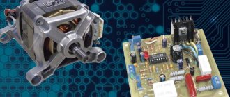
Semi-automatic welding
The semi-automatic machine consists of two main components:
- Wire feed unit. It feeds the wire into the welding zone and is additionally equipped with a shielding gas supply device.
- Arc power device. It is used as a welding rectifier or inverter.
Reference! The current of the semi-automatic device is regulated in the device feeding the arc.
Welding transformers
To bookmarks
Introduction
Welding transformer is a transformer designed to power electric welding installations. (GOST 16110-82)
The welding transformer (hereinafter referred to as ST ) converts the voltage of the supply network, reducing its value several times, while multiply increasing the value of the output current to thousands of amperes necessary to ensure the melting of the metal being welded.
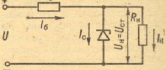
The key difference between welding transformers and other types of transformers is their so-called steeply falling current-voltage characteristic:
As can be seen from the graphs above, for transformers with a falling current-voltage characteristic, when the current increases (i.e. at the moment of ignition of the welding electric arc), the output (welding) voltage sharply decreases, in contrast to a conventional transformer, the voltage of which decreases smoothly. This feature of the CT makes it possible to ensure the stability of the electric arc, as well as the possibility of its operation in short circuit mode, which is critical for conventional transformers.
Features of welding transformers
The most common method of welding metals by fusion is electric arc welding. An electric arc is usually called a powerful, long-lasting electrical discharge in an environment of ionized gases between energized electrodes. This releases a large amount of heat. The gas in the arc gap is heated to a temperature of 5000-7000°C and is in a plasma state. The structure of the welding process using alternating current is shown in the figure below.
As already written above, the source of current for the electric arc is a welding transformer. When the CT is operating, frequent transitions of its operating modes occur from idle (at the moment when the arc goes out) to a short circuit (when the arc ignites and burns). This means that the welding transformer must have special operating properties that distinguish it from conventional power transformers.
These properties are determined by the external current-voltage characteristic (volt-ampere characteristic) of the welding transformer (current source). The external characteristic of the current source shows the dependence of the voltage at the terminals of the power source on the load current (welding arc). It must meet the characteristics of the static current-voltage characteristics of the welding arc.
An approximate view of the external incident current-voltage characteristic of the current source and the current-voltage characteristic of the welding arc is shown in the figure below.
The welding transformer lowers the network voltage to the value necessary to ignite the welding arc and at the same time to a safe value for a working person - this is 60-80V (no-load voltage). In addition, it performs the task of galvanic isolation between the welding circuit and the network voltage, that is, it electrically separates the welding current circuit from the network supplying the welding transformer, the connection between them is carried out only through electromagnetic induction, which in turn eliminates the possibility of injury to a person by welding current.
As already written above, the no-load voltage of the ST is limited to 60-80V. In this case, the no-load voltage should be no less than 1.8-2.5 times greater than the arc voltage, and the short-circuit current (Isc) should not exceed twice the value of the welding current (Isw), while changes in the welding current should be minimal. These conditions are met by the external steeply falling characteristic of the ST.
The no-load voltage of the ST is limited to a safe value, which is set at 60-80 Volts. But the no-load voltage must be no less than 1.8-2.5 times greater than the arc voltage, and the short-circuit current (Isc) must not exceed twice the value of the welding current (Isv), while changes in the welding current must be minimal . These conditions are met by the external steeply falling characteristic of the ST.
In steady state, the arc burning process is determined by the static characteristics of the current source and the welding arc . On current-voltage characteristics, this is the point of intersection of the curves, as in the figure below.
In manual arc welding, the process occurs at currents corresponding to the horizontal portion of the current-voltage characteristic of the welding arc, and the voltage of the current source is reduced to the required level. The value of the operating voltage (Uw) ST, rounded to the nearest whole number in volts, is determined by the value of the welding current Iw:
if Is up to 600A: Us = (20 + 0.04 Is) V,
if Isv is more than 600A: Usv = 44V,
where: Iw - welding current, A; Uwel – welding arc voltage, V.
Welding transformers can have three types of external characteristics: rising, hard and falling. Power sources for manual arc welding have a falling current-voltage characteristic.
Welding transformers for manual arc welding, as a rule, form a steeply falling external I-V characteristic in the range of low currents and a flat-dipping external I-V characteristic in the range of high currents.
Operating principle, design and main types of welding transformers
The principle of operation of CT is similar to conventional power transformers, although with its own characteristics necessary to obtain a falling current-voltage characteristic.
The welding transformer consists of two main parts - a choke and a step-down transformer, which contains two electrically unconnected windings located on a common closed magnetic circuit, one of which is connected to the alternating current source U1 and is called the primary winding (W1), and to the other winding, with a reduced voltage U2, the load is connected. This winding is called the secondary winding (W2).
Below is a general diagram of the welding machine.
The choke is used to regulate the welding current by changing the air gap δ. The larger the air gap, the lower the inductance of the inductor, therefore, the greater the current flowing in the secondary circuit.
At idle, when the current in the secondary winding I2=0, the voltage on the secondary winding W2 is maximum: U2=60-80V. After the arc is ignited, the voltage drops to 20-30 V, depending on the type of device.
All welding transformers can be classified according to the following criteria:
- Based on the nature of the magnetic core structure, transformers are divided into armored and rod types.
Rod-type transformers, compared to armor-type transformers, have a higher efficiency and allow higher current densities in the windings. Therefore, welding transformers are usually, with rare exceptions, of the rod type.
In addition, the rod-type magnetic circuit allows the primary and secondary windings to be separated over a greater distance, which leads to an increase in magnetic scattering and the creation of conditions for obtaining a falling external characteristic of the power source. Whereas transformers with an armor-type magnetic core have low (normal) magnetic dissipation, which leads to a rigid external characteristic when the voltage on the secondary winding decreases very slightly with increasing current. For example, this is good for power transformers, but it is not at all suitable for CT, where, under conditions of a steeply falling current-voltage characteristic, the voltage should decrease significantly with increasing arc current. This ensures normal operation of the CT during short circuits, i.e. when igniting and burning the arc.
- Based on the nature of the windings, transformers with cylindrical, spaced and disk windings are distinguished, as in the figure below: I – primary winding, II – secondary winding.
In transformers with cylindrical windings , one winding is wound on top of the other. Since the windings are located at a minimum distance from each other, almost the entire magnetic flux of the primary winding is coupled with the turns of the secondary winding. The concentric arrangement of the windings ensures low (normal) magnetic leakage. Because of this, such a transformer has a rigid external current-voltage characteristic and cannot provide stable ignition and combustion of the welding arc during manual welding with coated electrodes.
In transformers with spaced windings , the primary and secondary windings are located on different transformer rods. Since the windings are distant from each other, a significant part of the magnetic flux of the primary winding is not connected to the secondary winding. Such transformers have increased magnetic dissipation. A transformer with separated windings has the necessary falling external characteristic, where the operating current is approximately 80% of the short circuit current.
In transformers with disk windings , the primary and secondary windings are also removed from each other, but at a smaller distance compared to transformers with spaced windings. Therefore, in terms of leakage inductance, transformers with disk windings occupy an intermediate position. Such transformers also have increased magnetic dissipation. They have a falling external characteristic, but their operating current is approximately 50% of the short circuit current, i.e. the operating current is approximately two times less than the short-circuit current, which is in good agreement with the requirements for manual arc welding.
- According to the welding current adjustment device:
- transformers with inductive reactance;
- transformers with a choke in a separate housing;
- transformers with a choke in a single housing;
- transformers with a moving magnetic shunt;
- transformers with moving coils.
Inductive Resistance Welding Transformer
In transformers with cylindrical windings that have low magnetic dissipation, in order to obtain a falling external characteristic that ensures stable ignition and arc burning, the transformer must be equipped with an additional device - a choke (reactive coil) X L , which has a large inductive reactance, as in the figure below .
To smoothly regulate the welding current, the choke is an adjustable inductive reactor connected to the welding circuit in series with the secondary winding of transformer W2. The choke provides a decreasing relationship between the source voltage and the arc current, and makes it possible to regulate the welding current by changing the value of the reactance XL .
In this case, the short circuit current can be found using the formula:
Iкз= Uxx/ХL,
where Uхх is the open-circuit voltage of the ST (without load), XL is the inductor resistance.
To stepwise adjust the welding current, the inductor winding can be made with taps, and then these taps can be switched, as shown in the inset of the figure above.
These are the technologically simplest options for obtaining a falling external characteristic of a power source. But the significant inductive reactance of the welding transformer leads to a decrease in its power factor cosph, which usually does not exceed 0.4-0.5. Despite such a low power factor, CTs with a choke (ballast rheostat) are still used for welding with alternating current.
The disadvantage of the throttle welding current regulator is the small range of current regulation.
Welding transformer with choke in a separate housing
Transformers with windings spaced apart have increased magnetic dissipation. In this case, the ST has a choke with an additional winding W3 and is structurally made either in the form of two separate devices or in the form of a single housing.
Welding machines with a separate choke consist of a step-down transformer and an external choke - a current regulator.
The inductor core is made of thin transformer steel plates and consists of two parts: a fixed part, on which the W3 inductor winding is located, and a movable part, moved by a screw. In series with the secondary winding W2 of the transformer, the inductor winding W3 is connected to the welding circuit.
The welding current is adjusted by changing the size of the air gap in the magnetic circuit of the choke. The welding current is proportional to the size of the air gap. As the air gap increases, the inductive reactance of the choke decreases, and the welding current increases. If the air gap is eliminated altogether, then the inductor takes on the role of a coil, and then the current value will take on a minimum value. This regulation of the welding current allows you to adjust the welding mode smoothly and with sufficient accuracy.
Below is a schematic design of a welding machine with a choke in a separate housing.
Now transformers with a choke in a separate housing have been discontinued and replaced by devices in a single-case version with a similar principle of operation.
Welding transformer with choke in a single housing
In welding machines with a built-in choke, the additional magnetic circuit is located above the main magnetic circuit of the transformer. Such a device is structurally made in one body. The throttle consists of fixed and moving parts, between which there is an adjustable air gap.
The current adjustment is similar to the diagram presented above; the larger the gap, the greater the welding current.
Below is a schematic design of a welding machine with a choke in a single housing.
The disadvantages here are significant weight, dimensions, difficulty in obtaining a high-quality weld, significant energy consumption, but there are also advantages: this design of the welding machine allows you to smoothly regulate the welding current, it is extremely reliable in operation and is relatively inexpensive. This is often the deciding factor for the consumer.
Welding transformer with moving magnetic shunt
Also, for transformers with increased magnetic dissipation , the welding current can smoothly change with the help of movable sections of magnetic circuits, called magnetic shunts . Such transformers have on each core one winding W1 and W2, between which, in a special channel, a shunt is located. There is an air gap between the shunt and the core rods, which can change when the movable magnetic shunt moves.
When a magnetic shunt is introduced into the magnetic circuit of the transformer (reducing the air gap), part of the magnetic flux created by the primary winding is removed by the magnetic shunt and therefore this part of the magnetic flux bypasses the secondary winding. In this case, the efficiency of energy transfer from the primary winding to the secondary winding decreases (the inductive reactance of the transformer increases) and the welding current decreases. This method provides smooth control of the welding current.
The advantages of the welding machine include smooth adjustment of the welding current, simplicity of design, reliability, relatively low price, as well as unpretentiousness to environmental conditions.
The disadvantages include a relatively low efficiency (up to 80%), large weight and dimensions, and restrictions on the materials with which welding work can be performed.
Moving coil welding transformer
In transformers with disk windings , as already mentioned, increased magnetic dissipation .
The transformer has a magnetic core in the form of elongated rods, on which there are two pairs of coils: one pair with a primary winding, and the second pair with a secondary winding. To expand the limits of welding current regulation, transformers provide switching to low or high current modes. Parallel connection of the secondary winding coils ensures operation at high currents. The series connection of the secondary winding coils ensures operation in low current mode. This switching is an additional option for stepwise control of the welding current. Within each mode, smooth regulation of the welding current is possible. Below is a diagram of a moving coil transformer.
The primary coils are fixed motionless. The secondary winding coils are moved manually by a screw mechanism. Smooth control of the welding current is carried out by changing the distance between the coils of the primary and secondary windings of the transformer. As the distance between the coils decreases, the inductive resistance of the welding circuit decreases, and the welding current increases and vice versa. In the primary circuit, a capacitor C is connected parallel to the winding, increasing the power factor (cosph).
The bulk of AC welding transformers are made on the basis of transformers with disk movable windings. The advantage of such MTs is their simplicity of design without expensive parts, which means a more affordable cost of both the equipment itself and its repair. They have certain advantages in terms of the range and smoothness of regulation of the welding current. Although they are quite bulky and heavy. Built-in wheels are used to move them.
Marking of welding transformers
A certain system is adopted in the designation of power supplies. The complete symbol consists of alphabetic and digital indices.
1) The first letter indicates the type of power source :
T - transformer, G - generator, A - unit, B - rectifier, U - specialized source-installation;
2) The second letter indicates the type of welding:
D - arc, P - plasma;
3) The third letter is the welding method:
F - under a layer of flux, G - in a shielding gas environment, U - a universal power source for several welding methods. The absence of a letter in the third place corresponds to manual welding with coated electrodes;
4) The fourth letter is the method of regulating the welding current:
M – mechanical, E – electrical;
5) The fifth letter is the number of welding posts:
M – for multi-station welding (no designation indicates one station);
6) The next two digits are the rated welding current:
rounded in tens of Amperes;
7) Last one or two digits:
indicate the registration number in development;
 The following letter (or two) means the climatic version ST:
HL - for cold climates, U - for temperate climates, T - for tropical climates;
9) The last digit indicates the category of power supply placement:
1 - for work in the open air, 2 - in rooms with free access to outside air, 3 - in closed rooms, 4 - closed rooms with an artificial microclimate, 5 - in rooms with high humidity.
For example, let’s decipher the structural designation (marking) of the TDM-401U2 welding transformer:
Characteristics and passport data of power supplies
The main parameters of welding transformers include:
1) Rated supply voltage Unom, V:
The voltage required for the operation of the welding transformer. Typically 220V or 380V.
2) Rated welding current Iw, A:
Rated welding current - the maximum welding current in normal (not emergency) operating mode of the ST.
3) Welding current control limits A:
The current adjustment range ensures work with thin electrodes and parts at low current, and thick enough electrodes for welding massive parts at high current.
4) Limit value of open circuit voltage Uхх, V:
Voltage on the secondary winding of the CT without load. This characteristic is responsible for the ease of appearance of the welding arc. The higher the voltage, the easier the arc will appear. But it is limited to 60-80V to ensure the safety of the welder.
5) Rated operating voltage Urab, V:
The voltage that is necessary to maintain a stable arc. The possibility of welding metal of a certain thickness also depends on this parameter. The arc voltage during operation is about 20-30V.
6) Maximum power S, kVA:
The maximum value of the operating current CT, and therefore the thickness of the parts being welded, depends on the value of this parameter.
7) Nominal operating mode - load duration PN, %
PN is determined by the ratio of welding time to the sum of welding time and idling time and is expressed in %:
PN=tsv/(tsv+txx)×100%.
The duty cycle of industrial STs for manual arc welding is usually 60% at rated current (for example, 6 min – work, 4 min – pause).
Rated supply network frequency ƒnom, Hz:
Rated frequency of the supply voltage (50 Hz.)
This passport data is applied to a metal plate, which is called a plate, and is fixed in a visible place on the ST. The product labeling must contain basic (mandatory) and additional data characterizing the product. Marking is carried out in accordance with GOST 18620-86. Consider, for example, the plate ST TDM-401U2:
Was this article useful to you? Or maybe you still have questions ? Write in the comments!
Didn’t find an article on the website on a topic that interests you regarding electrical engineering? Write to us here. We will definitely answer you.
↑ Up
0
https://elektroshkola.ru/transformatory/svarochnye-transformatory/