It is known that the brightness of an LED depends very much on the current flowing through it. At the same time, the LED current depends very sharply on the supply voltage. This results in noticeable brightness ripples even with slight power instability.
But ripple is not scary; what’s much worse is that the slightest increase in the supply voltage can lead to such a strong increase in the current through the LEDs that they simply burn out.
To prevent this, LEDs (especially powerful ones) are usually powered through special circuits - drivers, which are essentially current stabilizers. This article will discuss circuits of simple current stabilizers for LEDs (on transistors or common microcircuits).
Parametric stabilizer
Its operating principle is based on the properties of semiconductor devices. The current-voltage characteristic of a semiconductor - a zener diode is shown in the graph.
During turn-on, the zener diode's properties are similar to those of a simple silicon-based diode. If the zener diode is turned on in the opposite direction, the electric current will initially increase slowly, but when a certain voltage value is reached, breakdown occurs. This is a mode where a small voltage increase creates a large zener diode current. The breakdown voltage is called stabilization voltage. To avoid failure of the zener diode, the current flow is limited by resistance. When the zener diode current fluctuates from the lowest to the highest value, the voltage does not change.
The diagram shows a voltage divider, which consists of a ballast resistor and a zener diode. A load is connected in parallel to it. When the supply voltage changes, the resistor current also changes. The zener diode takes over the changes: the current changes, but the voltage remains constant. When you change the load resistor, the current will change, but the voltage will remain constant.
Do LED bulbs need to be recycled?
LEDs that have lost their consumer properties are classified as waste of the fourth hazard class, that is, they are considered low-hazard. Materials used during the production stage can have a negative impact on the environment and must be recycled.
Hazard class, waste composition and FKKO code
LED lamps are waste of hazard class IV. Enterprises engaged in the production of lighting equipment are required to carry out their certification. This is described in detail in Russian Government Decree No. 712, issued on September 16, 2013.
Additional information: According to the Federal Classification of Municipal Waste (FKKO), LEDs are designated with the code 4 82 415 01 52 4.
Any LED lamp is multi-component. It consists of:
- base elements;
- aluminum body parts;
- polycarbonate;
- plastic.
All these components must be recycled or used in secondary production after recycling. No chemicals are used in the disposal or recycling process. Sorting is carried out without the use of personal protective equipment.
What the law says, Rospotrebnadzor requirements
LED lighting devices are manufactured in Russia according to GOST R 54815-2011/1EC/PAS 62612/2009. Often people who use such lamps at home throw them into ordinary garbage containers, which is contrary to the requirements of Rospotrebnadzor.
Before recycling LED lamps, the structure must be disassembled into individual elements and sorted by materials. The rest is taken care of by special processing enterprises.
Administrative responsibility for individual entrepreneurs and organizations
If waste LED lighting devices do not have waste certificates for products of the fourth hazard class, the enterprise bears administrative responsibility. According to the current regulatory framework, the violator is obliged to pay penalties in the amount of up to 250 thousand rubles. In addition, organizations can issue an administrative order to suspend activities for up to three months.
Compensation stabilizer
The device discussed earlier is very simple in design, but makes it possible to connect power to the device with a current that does not exceed the maximum current of the zener diode. As a result, voltage stabilizing devices are used, which are called compensation devices. They consist of two types: parallel and serial.
The device is named according to the method of connection to the adjustment element. Compensating stabilizers of the sequential type are usually used. His diagram:
The control element is a transistor connected in series with the load. The output voltage is equal to the difference between the values of the zener diode and the emitter, which is several fractions of a volt, therefore it is considered that the output voltage is equal to the stabilizing voltage.
The considered devices of both types have disadvantages: it is impossible to obtain the exact value of the output voltage and make adjustments during operation. If it is necessary to create the possibility of regulation, then a compensatory type stabilizer is manufactured according to the following scheme:
In this device, regulation is carried out by a transistor. The main voltage is supplied by a zener diode. If the output voltage increases, the base of the transistor becomes negative in contrast to the emitter, the transistor will open by a larger amount and the current will increase. As a result, the negative voltage at the collector will become lower, as well as at the transistor. The second transistor will close, its resistance will increase, and the terminal voltage will increase. This leads to a decrease in the output voltage and a return to its previous value.
When the output voltage decreases, similar processes occur. You can adjust the exact output voltage using a tuning resistor.
Principles for calculating characteristics
Parametric voltage stabilizer
For the simplest calculation of characteristics, the following data is required:
- Supply voltage;
- Load current;
- Output voltage.
Calculation procedure:
- Based on the output parameters, the type of stabilizing element is determined;
- The key element is selected according to the following criteria:
- Stabilization coefficient Вst≥In/Ist;
- The permissible collector-emitter voltage is greater than the maximum input voltage;
- The maximum collector current must be greater than the load.
Stabilizers on microcircuits
Such devices in the integrated version have increased characteristics of parameters and properties that differ from similar semiconductor devices. They also have increased reliability, small dimensions and weight, as well as low cost.
Series regulator
- 1 – voltage source;
- 2 – Adjustment element;
- 3 – amplifier;
- 4 – main voltage source;
- 5 – output voltage detector;
- 6 – load resistance.
The adjustment element acts as a variable resistance connected in series with the load. When the voltage fluctuates, the resistance of the adjustment element changes so that compensation for such fluctuations occurs. The control element is influenced by feedback, which contains a control element, a main voltage source and a voltage meter. This meter is a potentiometer from which part of the output voltage comes.
The feedback adjusts the output voltage used for the load, the output voltage of the potentiometer becomes equal to the main voltage. Voltage fluctuations from the main one creates some voltage drop at the regulation. As a result, the output voltage can be adjusted within certain limits by the measuring element. If the stabilizer is planned to be manufactured for a certain voltage value, then the measuring element is created inside the microcircuit with temperature compensation. If there is a large output voltage range, the measuring element is performed behind the microcircuit.
Parallel stabilizer
- 1 – voltage source;
- 2 – regulating element;
- 3 – amplifier;
- 4 – main voltage source;
- 5 – measuring element;
- 6 – load resistance.
If we compare the circuits of stabilizers, then a device of a sequential type has increased efficiency at partial load. A parallel type device consumes constant power from the source and supplies it to the control element and the load. Parallel stabilizers are recommended for use with constant loads at full load. The parallel stabilizer does not create a danger in the event of a short circuit, the sequential type does not create a danger during idle. At a constant load, both devices create high efficiency.
General concepts
The principle of arc welding is well known. Let's refresh our memory of the basic concepts. To obtain a welding joint, an arc must be created. An electric arc occurs when voltage is applied between the welding electrode and the surface of the material being welded. The arc current melts the metal, forming a molten pool between the two ends. After the seam has cooled, we obtain a strong connection between the two metals.
In Russia, alternating current is regulated at a frequency of 50 Hz. Power for the welding machine is supplied from the mains with a phase voltage of 220 V. Welding transformers have two windings: primary and secondary. The secondary voltage of the transformer is 70 V.
Separate manual and automatic welding modes. In a home workshop, welding is carried out manually. We list the parameters that can be changed manually:
- welding current;
- arc voltage;
- welding electrode speed;
- number of passes per seam;
- diameter and brand of electrode.
The correct selection and maintenance of the necessary parameters throughout the welding process are the key to a high-quality welded joint.
When carrying out manual arc welding, it is necessary to correctly distribute the current. This will allow you to make a high-quality seam. The stability of the arc directly depends on the magnitude of the welding current. Experts select it based on the diameter of the electrodes and the thickness of the materials being welded.
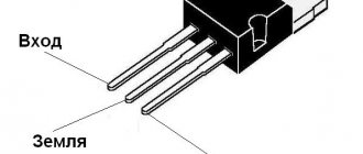
Stabilizer on a chip with 3 pins
Innovative variants of sequential stabilizer circuits are made on a 3-pin microcircuit. Due to the fact that there are only three outputs, they are easier to use in practical applications, since they displace other types of stabilizers in the range of 0.1-3 amperes.
- Uin – raw input voltage;
- U out – output voltage.
You may not use containers C1 and C2, but they allow you to optimize the properties of the stabilizer. Capacity C1 is used to create system stability, capacitance C2 is needed for the reason that a sudden increase in load cannot be tracked by the stabilizer. In this case, the current is supported by capacitance C2. In practice, 7900 series microcircuits from Motorola are often used, which stabilize a positive voltage value, and 7900 – a value with a minus sign.
The microcircuit looks like:
To increase reliability and create cooling, the stabilizer is mounted on a radiator.
Design and operating principle
The stabilizer ensures constant current when it deviates.
The stabilizer ensures constant operating current of LED diodes when it deviates from the norm. It prevents overheating and burnout of LEDs, maintains constant flow during voltage surges or battery discharge.
The simplest device consists of a transformer, a rectifier bridge connected to resistors and capacitors. The action of the stabilizer is based on the following principles:
- supplying current to the transformer and changing its limiting frequency to the mains frequency - 50 Hz;
- voltage adjustment to increase and decrease with subsequent frequency equalization to 30 Hz.
The conversion process also uses high-voltage rectifiers. They determine the polarity. Stabilization of the electric current is carried out using capacitors. Resistors are used to reduce interference.
Second scheme
The device diagram shown in Fig. 2 has no such drawback. This allows it to be used in almost any equipment: both in various digital, and in sound-reproducing and radio-receiving devices.
The stabilizer contains a switching composite transistor VT1, VT2, a switching diode VD2 and inductor L1. The control unit includes a support element on the transistor VTZ and a comparator DA1.
At the output of the stabilizer, a transistor filter VT4, VT5 is turned on. The basis of the control unit is the DA1 comparator based on the K140UD12 type op-amp. A micro-power reference element made on the reverse-biased emitter junction of the VTZ transistor is connected to its inverting input. Its stabilization voltage (avalanche breakdown) of 7...7.5 V is provided at a current of 20...30 µA.
Rice. 2. Circuit of an economical switching voltage stabilizer.
The non-inverting input of the op-amp is supplied with a signal from the resistive divider R5 - R7. The output voltage is adjusted by potentiometer R6.
Capacitor C3 increases the phase shift of the feedback signal, which is necessary for the cyclic nature of the device. It also determines the operating frequency and significantly influences the magnitude of pulsations.
The output of the comparator is connected to the base of the composite transistor (VT1, VT2) through resistor R3, which sets the control current, and a zener diode VD1, which ensures cutoff of the control current and reliable closing of the switching transistor over the entire input voltage range. Capacitor C2 suppresses high-frequency interference.
The output of the stabilizer includes not a traditional LC filter, but a transistor one, which improves the dynamic characteristics of the device and suppresses ripple by at least 40 dB.
The transistor filter has another advantage - “soft” switching on of the stabilizer: its output voltage gradually increases over 2...4 s. The negative aspect of using a transistor filter is that the efficiency of the stabilizer decreases by 6...8%.
Choke L1 contains 28 turns of PEV-2 0.57 wire, wound on an armored magnetic core B14 made of 2000NM ferrite. A non-magnetic gap of 0.2 mm in the magnetic core is ensured by a paper gasket.
The transistors of the device at rated current do not require a heat sink. If the stabilizer is intended to be operated at a load current of more than 50 mA, then the transistor VT1 should be of the KT81x type and should be installed on a heat sink with an area of 10... 15 cmg. It is permissible to use transistors KT639, KT644, then the output current of the stabilizer can be increased to 0.5 A.
Stabilization of household voltage
The desire to provide stabilized voltage to the household network is an obvious phenomenon. This approach ensures the safety of the equipment in use, often expensive and constantly needed on the farm. And in general, the stabilization factor is the key to increased safety in the operation of electrical networks.
For domestic purposes, a stabilizer is most often purchased for a gas boiler, the automation of which requires connection to a power supply, for a refrigerator, pumping equipment, split systems and similar consumers.
Industrial design of a mains voltage stabilizer, which is easy to purchase on the market. The range of such equipment is huge, but there is always the opportunity to make your own design
This problem can be solved in different ways, the simplest of which is to buy a powerful voltage stabilizer manufactured industrially.
There are a lot of offers of voltage stabilizers on the commercial market. However, purchasing options are often limited by the cost of devices or other factors. Accordingly, an alternative to purchasing is to assemble a voltage stabilizer yourself from available electronic components.
Provided you have the appropriate skills and knowledge of electrical installation, the theory of electrical engineering (electronics), wiring circuits and soldering elements, a homemade voltage stabilizer can be implemented and successfully used in practice. There are such examples.
Stabilization equipment made with your own hands from available and inexpensive radio components may look something like this. The chassis and housing can be selected from old industrial equipment (for example, from an oscilloscope)
Time relay
The TL431 has found its use not only as a voltage reference source, but also in many other applications. For example, due to the fact that the input current of TL431 is 2-4 μA, a time relay can be built on the basis of this microcircuit: when contact S1 opens, C1 begins to slowly charge through R1, and when the voltage at the input of TL431 reaches 2.5 V, the output transistor DA1 opens and through The LED of the PC817 optocoupler will begin to flow current, and accordingly the phototransistor will open and close the external circuit. In this circuit, resistor R2 limits the current through the optocoupler and stabilizer (for example, 680 Ohms), R3 is needed to prevent the LED from igniting from the TL431’s own current (for example, 2 kOhms).
Tags: machine, ampere, anode, bipolar, sconce, type, choice, house, , protective, isolate, like, capacitor, , magnet, magnetic, power, voltage, nominal, limiter, variable, connection, constant, potential, principle , wire, start, , work, size, calculation, regulator, resistor, relay, row, light, LED, connection, resistance, means, stabilizer, zener diode, circuit, ten, type, current, transistor, transformer, , filter, photo , photoresistor, shield
Detailed Assembly Instructions
The circuit being considered for self-production is rather a hybrid option, since it involves the use of a power transformer in conjunction with electronics. The transformer in this case is used from among those that were installed in televisions of older models.
This is roughly the kind of power transformer you will need to make a homemade stabilizer design. However, the selection of other options or do-it-yourself winding cannot be ruled out.
True, TV receivers, as a rule, installed TS-180 transformers, while the stabilizer requires at least a TS-320 to provide an output load of up to 2 kW.
Step #1 - making the stabilizer body
To make the device body, any suitable box based on an insulating material - plastic, textolite, etc. is suitable. The main criterion is sufficient space for placing a power transformer, electronic board and other components.
It is also possible to make the body from fiberglass sheets by fastening individual sheets using corners or in another way.
It is permissible to select a housing from any electronics that is suitable for placing all the working components of a homemade stabilizer circuit. You can also assemble the case yourself, for example, from fiberglass sheets
The stabilizer box must be equipped with grooves for installing a switch, input and output interfaces, as well as other accessories provided by the circuit as control or switching elements.
Under the manufactured case, you need a base plate on which the electronic board will “lie” and the transformer will be fixed. The plate can be made of aluminum, but insulators should be provided for mounting the electronic board.
Step #2 - making a printed circuit board
Here you will need to initially design a layout for the placement and connection of all electronic parts according to the circuit diagram, except for the transformer. Then a sheet of foil PCB is marked along the layout and the created trace is drawn (printed) on the side of the foil.
Next, the board is etched using an appropriate solution (electronics engineers should be familiar with the method of etching boards).
You can make a printed circuit board for a stabilizer using quite affordable methods at home. To do this, you need to prepare a stencil and a set of tools for etching on foil PCB
The printed copy of the wiring obtained in this way is cleaned, tinned and all the radio components of the circuit are installed, followed by soldering. This is how the electronic board of a powerful voltage stabilizer is manufactured.
In principle, you can use third-party PCB etching services. This service is quite affordable, and the quality of the “signet” is significantly higher than in the home version.
Step #3 - assembling the voltage stabilizer
A board equipped with radio components is prepared for external wiring. In particular, external communication lines (conductors) with other elements - a transformer, switch, interfaces, etc. are output from the board.
A transformer is installed on the base plate of the housing, the electronic circuit board is connected to the transformer, and the board is secured to the insulators.
An example of a homemade relay-type voltage stabilizer, made at home, placed in a housing from a deteriorating industrial measuring device
All that remains is to connect the external elements mounted on the case to the circuit, install the key transistor on the radiator, after which the assembled electronic structure is covered with the case. The voltage stabilizer is ready. You can start setting up with further testing.