To use the device, you need to know how and in what sequence to put the 2t30 theodolite device into operation, how to check and adjust it. It is necessary to be able to recognize the parts of the device and its operating principle to measure angles both horizontally and vertically.
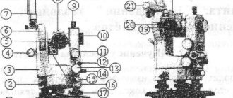
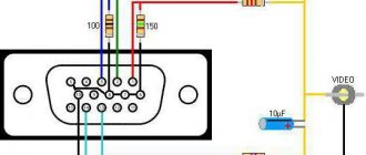
General diagram of the main parts and axes of the theodolite.
Applicable:
- for topographic surveys;
- tacheometric works, survey processes;
- surveying measurements;
- on construction sites during marking work that does not require perfect accuracy.
Device characteristics
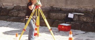
Tripod and optical plummet - used to install the theodolite above a point fixed on the ground.
Angular measurements are needed to determine the position of objects in space. Such manipulations are performed for a triangulation network. A classic type of work is geodetic measurements for the construction of all kinds of structures.
The accuracy of the device, close to ideal, is expressed in minutes, fractions of seconds. The theodolite has an optical and mechanical device for measuring angles, distances, and magnetic azimuths. The devices are divided into types depending on accuracy, including technical 2t30. The digital indices in the name indicate accuracy, that is, the square error in determining the angle in one step in seconds. Theodolite 2t30 device consists of components:
- ratchet, diopter ring, cap with adjustable screws of the thread network;
- sight with optics, vertical ring, pipe spacer;
- screws for adjusting, securing the dial, alidade, pipe, lifting, adjusting the dial;
- cylinder shape level, case base, pipe, stand;
- elements, mirror surfaces.
The reference compass is necessary for measuring magnetic azimuths and is installed in a groove located on the side cover of the vertical circle of the theodolite.
It is equipped with a micrometer, which increases the accuracy of measurements. With the help of its elements, geometric leveling is done, the plummet allows you to carry out work in a three-stand system. The distance can be calculated using a leveling rod.
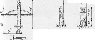
The level-cylinder moves the horizontal dial perpendicular to the line in a vertical state. It is a glass tube like an ampoule, its cut is an arc with a radius of 3.5 to 200 m. This container is filled, as a rule, with alcohol, ether, that is, easily mobile properties. It is sealed while heated. As it cools, a bubble is created. The point in the center of the ampoule scale is taken as zero.
Devices of this nature have levels in the shape of a cylinder or circle; they differ in division parameters, sensitivity, and design.
The cylinder of the ampoule is framed in a metal frame, it has an adjustment screw, there are divisions on the outside of the tube with a distance of 2 mm, and the point in the center is the zero point. Its axis is a line related to the level inside, at the zero point.
Field of view of the reference microscope.
Round - a glass ampoule, polished inside, with a certain roundness. Here the zero point is the center in the circle. The axis is the normal, laid through the zero, it is perpendicular.
The zero position is made smoother by contact levels. They consist of a level cylinder, above which there is a device with optics that transmits the edges of the ends of the bubble to the lens. It is placed at zero when its opposite faces overlap.
The level price is the angular indicator of the displacement of the bubble in one stroke. It can be in cylindrical 5-60, in round – 5-20.
Sensitivity is the smallest noticeable bubble movement, usually 0.1 stroke or 0.2 mm. Pipe elements - screws, optical parts, dimensional grid. It houses the sighting and optical axes. The first connects the lens to the threads with a dimensional network. The second eyepiece is connected to the lens.
Device structure
Theodolite marking “2T30P” is deciphered as follows:
- “2” is a second generation instrument, which has some improvements compared to the previous one;
- "T" - theodolite;
- “30” - accuracy class, which determines the error in minutes, classifies this theodolite as a technical instrument with low accuracy;
- “P” - a special device of the theodolite telescope provides an image of direct vision.
The telescope has an average magnification value of 20x, the direct type image is formed clear and contrasting, providing greater ease of work and maximum comfort for the operator’s vision. The level located on the telescope allows you to perform simple leveling using the tool.
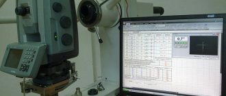
The design is equipped with a scale microscope, the reading of which is carried out according to a marked scale. The vertical axis system is repeating.
The built-in 1.8x optical plummet, located on a removable stand, allows you to quickly install the theodolite into its working position at the point of the survey being performed. The detachable design of the stand with three removable screws allows the use of a more accurate three-stand method of work, used in precise polygonometry or contour surveying, compared to the usual three-stand method.
The case, made of heavy-duty composite material, provides maximum protection for theodolite mechanisms from dust contamination, moisture, condensation and other unpleasant factors. There is a landing groove for attaching a compass for the purpose of determining magnetic azimuths.
The standard package includes:
- the instrument itself with a removable stand;
- set of adjustment tools;
- technical documentation: operating instructions for theodolite 2T30P, technical passport, factory verification certificate;
- a frame case that is firmly connected to the base of the device with locks and serves for comfortable transportation and reliable storage.
Optionally, the kit may include:
- optical plummet;
- compass;
- geodesic tripod;
- microscope illumination lamp.
The wide range of temperatures possible for the theodolite to operate correctly, as well as the absence of electronic elements in the design of the instrument, allows this model to be used in different climatic zones and under different weather conditions; even critically low temperatures are not dangerous for a reliable and consistent device.
- 1 - ratchet,
- 2 — diopter ring,
- 3 - cap, under which the corrective screws for the mesh of threads are located,
- 4 — optical sight,
- 5 - vertical circle,
- 6 - column,
- 7 — dial fixing screw,
- 8 — base of the case,
- 9 — deadbolt,
- 10 — corrective level screws,
- 11 — alidade fixing screw,
- 12 — level,
- 13 — fixing screw of the telescope,
- 14 — telescope,
- 15 — telescope guide screw,
- 16 — alidade guide screw,
- 17 — stand,
- 18 — lifting screws,
- 19 — dial guide screw,
- 20 - microscope eyepiece,
- 21 - mirror.
Working Condition: Features
The tube must be adjusted by eye, that is, rotate the eyepiece until the threads become clear. The ratchet is adjusted until the target is clear. The horizontal position is adjusted with a screw for aiming, first the alidade is secured, the vertical position is adjusted with a screw, then secured with another screw.
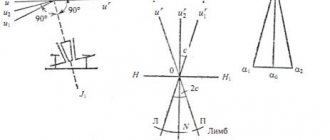
Diagram of the main axes of the theodolite.
The field of view is the area viewed by the pipe when stationary. The strokes and numbers fall into the field of view of the microscope; it is fixed by eye with a diopter ring until it is illuminated.
The horizontal circle is a limb; there are degrees on it behind the clockwise. The circles have gradations of 1°. There is 359° in horizontal, vertical has 0-75° and from 0 to – 75°.
The alidade serves as a reference detail; it is coaxial to the plane with the gradation. A vertical circle is the same as a horizontal circle, it measures oblique angles.
The cylinder-level bubble is adjusted with bolts.
additional characteristics
Device Features:
- Axles.
- OO1 – vertically, the axis of rotation of the device.
- UU1 – in the level cylinder.
- WW1 – for viewfinder, lens and dimensional network.
- VV1 – pipes.
They are correctly set as follows: UU1 ^ OO1, WW1 ^ VV1, VV1 ^OO1 The dial line is a counting indicator, accuracy up to 0.5′. When the value in the circle is vertical, “-” is counted with the indicators of the row below with “-” (-4.0, from right to left). Magnetic azimuth is measured by a reference compass; it is fixed vertically on the side cover of the circle. Use the locking screw to set the device to zero. The mirror shows the arrow, it is brought to the desired position. The pointer is adjusted in a non-functional state using a compass screw.
Storage, transfer
Verification diagram: a – level, b – sighting axis, c – horizontal axis.
There is a special case with sockets for this. When packing it, the screws are placed in the middle position, the pipe is laid horizontally, the moving parts are fixed, and the lifting screws are tightened until they stop. Using a tripod with an optical plummet, the device is placed on top of a point in space, that is, above the peak of the angle.
Its legs are hinged to the headbands, and the device is secured to them with a screw. The leg contains a plumb line case with thread. The plummet with optics is mounted in the rack. Having centered, the base is moved on a tripod head, so that the center in the network is aligned with a point in space. If there is no plumb line, then a plumb line with a thread is used for this. The device is fixed to the tripod with a bolt, and you can hang a plumb line on it.
Theodolite 2t30 verification and adjustment
To operate the device you must follow the rules. The vertical axis is plumb, and the sight is vertical. Due to transportation and handling of the device, they are disturbed, so verification and adjustment (regulation) must be done frequently. They are performed in some order. For the operating condition of the device, it is necessary to carry out verifications, as well as:
- Centering theodolite 2t30. The center of the horizontal plane is above the peak of the angle. This is done by using a plumb line with a thread, a plumb line, positioning the tripod, and moving the device on the tripod. The error is permissible up to 3 mm for horizontal angles.
- Leveling. The horizontal circle scale is plumb. The cylinder level is placed horizontally with the lifting bolts, they are rotated together in different directions, the bubble is brought to the center of the cylinder. The cylindrical level is moved 90° relative to the third bolt. It rotates, and the bubble is brought to the zero point again. This is done until the deviation is more than 1 stroke from the center. The error during operation is no more than half a stroke.
- Preparing the pipe. The eyepiece rotates until the reticle is clear, the ratchet until the object is clear. Parallax is eliminated by adjusting the ratchet.
Specifications
| Standard deviation with one measurement | 20" (for horizontal corners), 30" (for vertical) |
| Vertical angle measurement range | +60…-55° |
| Optical tube approach | 20 times |
| Image | direct vision |
| Compensator | absent |
| Reading device | scale system |
| Operating temperature range | -40 … +50°С |
| dimensions | 140×130×230 mm |
| Weight with stand | 2.3 kg (case weight 1.5 kg) |
The difference between the 2T30P model and the 2T30 is only in image formation; other technical and engineering characteristics and functions are identical.
User instructions for working with theodolite 2T30P.
Basic device verification
There are five verifications. The horizontal axis of the theodolite cylinder-level 2t30 is made perpendicular to the vertical axis I-I1. The aliduda is set to position the axis of the adjustable cylinder-level in a parallel plane to the lifting bolts, which place the bubble at the zero point. It is moved, and together the cylinder, by 180 degrees.
- If there is a bubble at the zero point or if it deviates by no more than 1 division, verification is done. If not, use screws to correct it by half the error value, the other half is removed with bolts for lifting. Bring the axis vertically to a plumb position. The cylindrical level is placed towards the adjusting bolts, the bubble is at zero. The alidade is rotated 90°, the bubble is inserted into the center with the third bolt. Make to an error of less than one line.
- The sight (pipe axis) V-V1 must be positioned opposite H-H1. The angle of error of the viewfinder from the perpendicular to the horizontal axis H-H1 is called collimation deviation. When checking, mark point M; it should be aligned with the axis of the pipe. They sight it, make a count (R) along the horizontal plane, pass the pipe through the zenith, direct it to a point, count again (L). If there is a collimation deviation, then: L – R ± 180° = 0. L and R – reading along the vertical plane on the left (CL) and on the right (CP). When deflected in the first guidance, the sighting axis will be in the VV ' state, after the second - V1-V1'. Then L – R ± 180° = 2s. As a result, c = (L – R ± 180°)/ It is necessary that the collimation error is not greater than the accuracy of twice the reading element (1′). To avoid unacceptable deviation, the alidade is placed on one of the accounts. Formulas: NR = R + c (for CP) or NL = L – s (for CL). Then the center of the network will move to the angle c. Bolts align its center with point M.
- H-H1 perpendicular to I-I1. On the wall, 20-30 m away, select point A, point the center of the axes. The pipe is placed horizontally, point a1 is marked, and the center of the network is projected into it. Passing the pipe through the zenith, point at the same point, and also mark point a2. Points a1 and a2 must coincide or be in a bisector of the network.
- Stroke the network vertically in a plane parallel to I-I1. The center is aimed at a vertical thread set at 5-10 m. When the pipe is rotated, the line and the thread coincide. Everything is done.
- The center axis is parallel to the vertical. The projection of the center is marked on a piece of paper and placed under a tripod. The fixing bolt is loosened and the device is moved. The center axis is parallel to the vertical axis.
Now everything is done.
1.3. Reports on horizontal and vertical circles:
T 30 2T 30, 2T 30P
Vertical circle counting_358
0
15' vertical circle count -0
0
27'
Horizontal circle count_ 59
0
32’horizontal circle counting125
0
34’
Field of view of the microscope