Information about the manufacturer of the IZH-250 screw-cutting lathe
The manufacturer of the screw-cutting lathe model IZH-250 is Izhevsk Machine-Building , founded in 1807.
The history of machine tool building at the Izhevsk Machine-Building Plant begins on July 28, 1930, after the issuance of Order No. 181 on the creation of a machine tool department.
The first machine-tool production product at the plant was a lathe with an external transmission.
The most popular models of universal lathes produced at different times were “Udmurt”, “Udmurt-2” (161-AM), IZH-250, 1I611P, 1IS611V, 95TS, 250ITVM, 250ITVMF1 and the IT42 CNC lathe.
Machine tools produced by the Izhmash machine-building plant
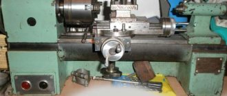
IZH-250 Universal screw-cutting lathe. Purpose, scope
The IZH-250 screw-cutting lathe is one of the first serial machines produced by the Izhevsk Machine-Building Plant in the post-war years. The machine was produced until 1964, when it was replaced by a much more advanced screw-cutting lathe 1I611P
.
The IZH-250 lathe was produced for a relatively short time (1960-1964). The machine has been radically redesigned in relation to its predecessor (model 161-AM (Udmurt-2)
).
Screw-cutting lathes, models IZH-250, are designed for turning on centers, chucks or collets, as well as for cutting metric, modular and inch threads for use in large and small enterprises.
The machines can be used in tool and instrument manufacturing related to the precision processing of small-sized parts.
The IZH-250P machine has an increased accuracy class and is used to perform more precise work.
Main technical characteristics of the IZH-250 screw-cutting lathe
Manufacturer: Izhevsk Machine-Building Plant Izhmash. Serial production began in 1960.
- The largest diameter of a Disk-type workpiece processed above the bed is Ø 250 mm
- The largest diameter of the Shaft type workpiece processed above the support is Ø 125 mm
- Distance between centers - 500 mm
- Height of centers - 150 mm
- Electric motor power - 2.6/3 kW
- Full machine weight - 1.5 t
Spindle of screw-cutting lathe IZH-250
- Spindle end - threaded M68x6
- Internal (tool) spindle cone - Morse 5
- The diameter of the through hole in the spindle is Ø 33 mm
- The largest diameter of the processed rod is Ø 30 mm
- Limits of direct spindle revolutions per minute (22 steps) - 16..2000 rpm
Feeds and threads of a screw-cutting lathe IZH-250
- Limits of longitudinal feeds - 0.07..2.17 mm/rev
- Transverse feed limits - 0.01..1.08 mm/rev
- Limits of metric thread pitches - (24 pcs) 0.2..6 mm
- Limits of modular thread pitches - 0.2..6 modules
- Limits of inch thread pitches - 24..3.5 threads per inch
Design features of the screw-cutting lathe IZH-250
The spindle of the IZH-250 screw-cutting lathe is mounted on bronze split adjustable plain bearings and has 22 rotation speeds: 12 revolutions from the gearbox through a V-belt drive and 10 speeds through the gearbox in the headstock.
The end of the spindle is threaded M68x6. A standard Ø200 mm cartridge is installed on an intermediate (adapter) flange, which is screwed onto the thread until it stops. The diameter of the hole in the spindle is Ø 33 mm for a rod Ø 30 mm. Morse taper 5.
The gearbox is installed in the left cabinet of the machine and is a four-axis gearbox, receiving movement from a flange electric motor. From the gearbox through a V-belt transmission, the movement is transmitted to the spindle. A friction plate clutch and brake are located on the drive shaft of the gearbox. The clutch provides on/off rotation of the spindle, and the brake reduces the spindle rotation time.
The feedbox receives movement through the guitar from the headstock gearbox.
The thread pitch and feed speed are selected using the handles on the front cover of the feed box.
support receives movement from the drive shaft connected to the output shaft of the feed box. When cutting threads, the movement of the caliper is ensured by the lead screw, and the lead shaft should not rotate.
The caliper apron converts the rotational movement of the lead shaft or lead screw into longitudinal and transverse movement of the caliper. The apron also provides manual longitudinal movement of the caliper from the flywheel.
Electrical equipment installed on the IZH-250 machine:
- The electric motor of the main movement drive is asynchronous, two-speed - 1420/2800 rpm, power - 2.6/3 kW, three-phase 380 V, type FT42-4/2.
- Electric motor for driving the lubrication oil pump is asynchronous with a squirrel-cage rotor - 1400 rpm, power - 0.18 kW, three-phase 380 V, type AOL12-4
- Cooling pump drive electric motor - 2800 rpm, power - 0.125 kW
- Irreversible magnetic starter with coil 380V, type PMI-1
- Reversible magnetic starter with a 380V coil for switching the direction of rotation of the main motion electric motor, type PMI-1R
- Two-pole thermal relay for protecting electric motors, type RT-1
Understanding the design of the machine
In the design of the 1I611P screw-cutting lathe, the following components are distinguished.
In its center there is a pulley mounted on the sleeve. This pulley, which drives the spindle assembly, is connected to the gearbox using 4 V-belts. From the receiving pulley, the spindle unit receives 12 rotation speeds by means of a gear coupling, and another 12 can be communicated to it through the search. The gear coupling or overdrive is connected using a special handle, which is located on the front part of the headstock housing - on its right side. To exclude the possibility of simultaneous start-up of the overdrive and the gear coupling, a locking mechanism is provided in the design of the front headstock. In addition, the design of the headstock has a mechanism responsible for increasing the pitch of the cut thread (8:1), as well as a snaffle, with the help of which rotation is transmitted to the guitar and then to the feed box.
READ How to Sawing on a Circular Bench
Front headstock of the machine 1I611P modern design
In fact, this is a gearbox that is responsible for the rotation speed of the spindle assembly. The 1I611P gearbox consists of 4 axes on which gears with different parameters are mounted. The drive for the gearbox is the main electric motor of the equipment, connected to it using flanges. Due to its own flat guides, the gearbox can move along the guides of the pedestal on which it is secured using bolted connections, which allows you to adjust the tension of the belts. A preselective mechanism, controlled by a corresponding flywheel, is responsible for adjusting the rotation speeds produced by the gearbox.
This unit is mounted on the left side of the feed box. For most types of threads (metric - ordinary accuracy), there is no need to change the gears on the guitar. In this case, if you need to cut high-precision threads, also modular and inch threads, replaceable gears are installed on the lathe, which allow you to do the processing without using the feedbox mechanism. To correctly set the characteristics of the guitar, you should read the passport of the lathe in question, which contains the corresponding table.
Thread cutting characteristics table is located Feed box
In the 1I611P lathe this unit has a closed design. The properties of the feed box allow you to cut metric threads with a standard pitch (0.2–48 mm) without using a set of replaceable gears.
Placing gears and shafts in the feed box
Screw-cutting lathe 250ITVM
When equipping shops for turning operations, a 250ITVM screw-cutting lathe is used, and more modern modifications manufactured on this basis are also widely used. The developers of this multifunctional device are mechanical engineering specialists from Izhevsk. The IZH machine, the original marking of which was exactly this, is used for turning work in a chuck, collet, and also in centers.
Location of machine components 250ITVM.01, 250ITVM.03, 250ITVMF1
Location of the main components of the lathe 250Itvm.01
List of components of the machine 250ITVM.01, 250ITVM.03, 250ITVMF1
- Bed 250ITVM.10.000 (250ITVM.03.10.000)
- Gearbox 250ITVM.17.000
- Feed box 250ITVM.30.000
- Guitar 250ITVM.25.000
- Front headstock 250ITVM.21.000
- Electrical equipment 250ITVM.90.000
- DRO wiring 250ITVMF1.94.000
- Guard (cartridge) 250ITP.86.000
- Apron 250ITVM.50.000
- Four-position tool holder 250ITP.61.000
- Guard (support) 1I611P.89.000
- Caliper 250ITVM.60.000
- Cooling 250ITP.70.000
- Rear headstock 250ITP.40.000
- Fencing 250ITVM.10.02.000
- Grease 250ITVM.74.000
Technical data
The 250ITVM screw-cutting lathe was developed for the purpose of processing small-sized workpieces. The technical characteristics of the machine completely determine its scope of application; the passport of this installation can be found in small workshops, school classrooms, and instrument-making shops.
Download the passport (operating instructions) of the 250ITVM machine
The model is able to guarantee high accuracy of the operations performed if the master performs a finishing fit or a semi-finishing procedure. When carrying out rough technological processing, the mechanisms of a lathe are subjected to maximum loads, which significantly reduces accuracy. The solution will be to use an improved modification of this series for these works.
Lathe IZH 250ITVM technical characteristics:
- The permissible length of the workpiece is 500 mm.
- The maximum diameter of the workpiece is 240 mm.
- The rod used (located in the chuck) is up to 24 mm.
- The cutter cross-section is 16x16 mm.
- The end part of the spindle is 4.
- Main drive rotation speed – 50-2500.
- Accuracy indicator according to GOST - the model belongs to class “B”, high accuracy.
- The total weight of the structure is 1180 kg.
Technical characteristics of the machine 250ITVM.01, 250ITVM.03, 250ITVMF1
| Parameter name | 250ITVM.01 | 250ITVM.03 | 250ITVMF1 |
| Main settings | |||
| Accuracy class according to GOST 8-82 | IN | IN | IN |
| The largest diameter of the workpiece processed above the bed, mm | 240 | 240 | 240 |
| The largest diameter of the workpiece processed above the support, mm | 168 | 168 | 168 |
| The largest diameter of the workpiece installed above the bed, mm | 300 | 300 | 300 |
| The largest diameter of the workpiece installed above the caliper, mm | 168 | 168 | 168 |
| Maximum workpiece length (RMC), mm | 500 | 750 | 500 |
| Spindle | |||
| Diameter of through hole in spindle passing through hole in spindle, mm | 25 | 25 | 25 |
| Maximum rod diameter, mm | 24 | 24 | 24 |
| Number of stages of direct rotation of the spindle, rpm | 21 | 21 | 21 |
| Spindle direct rotation frequency, rpm | 25..2500 | 25..2500 | 25..2500 |
| Number of spindle reverse rotation stages, rpm | 21 | 21 | 21 |
| Spindle reverse rotation frequency, rpm | 25..2500 | 25..2500 | 25..2500 |
| Size of the internal cone in the spindle, M | Morse 4 | Morse 4 | Morse 4 |
| Spindle end according to GOST 12593-72 | 4 | 4 | 4 |
| Permissible torque on the spindle, Nm | 1051,90 | 1051,90 | 1051,90 |
| Submissions | |||
| Maximum stroke length of the caliper carriage, mm | 500 | 500 | 500 |
| Price for dividing the longitudinal movement dial of the caliper, mm | 0,1 | 0,1 | 0,1 |
| Longitudinal movement per one revolution of the dial, mm | 20 | 20 | 20 |
| Maximum lateral movement of the caliper, mm | 165 | 165 | 165 |
| Dividing value of the caliper transverse movement dial, mm | 0,05 | 0,05 | 0,05 |
| Transverse movement per one revolution of the dial, mm | 3 | 3 | 3 |
| Maximum movement of the upper slide of the caliper, mm | 120 | 120 | 120 |
| Number of longitudinal feed stages | |||
| Limits of longitudinal working feeds, mm/rev | 0,01..1,8 | 0,01..1,8 | 0,01..1,8 |
| Number of cross feed stages | |||
| Limits of working cross feeds, mm/rev | 0,005..0,9 | 0,005..0,9 | 0,005..0,9 |
| Speed of fast movements of the caliper, longitudinal, m/min | No | No | No |
| Speed of fast movements of the caliper, transverse, m/min | No | No | |
| Number of metric threads to be cut | |||
| Limits of pitches of cut metric threads, mm | 0,2..48 | 0,2..48 | 0,2..48 |
| Number of inch threads to be cut | |||
| Limits of pitches of cut inch threads | 24..0,5 | 24..0,5 | 24..0,5 |
| Number of modular threads to be cut | |||
| Limits of pitches of cut modular threads | 0,2..12 | 0,2..12 | 0,2..12 |
| Number of cut pitch threads | No | No | No |
| DRO resolution in X/Z coordinates. mm | — | — | 0,001/ 0,005 |
| Tailstock | |||
| The size of the internal cone of the tailstock quill according to GOST 25557-82 | Morse 3 | Morse 3 | Morse 3 |
| Tailstock quill center according to GOST 13214-79 | Morse 3 | Morse 3 | Morse 3 |
| Maximum movement of the tailstock quill, mm | 85 | 85 | 85 |
| Rule division price, quill movement, mm | 1 | 1 | 1 |
| Limb division price, quill movement, mm | 0,05 | 0,05 | 0,05 |
| Transverse displacement of the quill, mm | ±10 | ±10 | ±10 |
| Electrical equipment | |||
| Number of electric motors on the machine | 3 | 3 | 3 |
| Main drive electric motor, kW/rpm | 3/ 1410 | 3/ 1410 | 3/ 1410 |
| Lubrication station electric motor, kW/rpm | 0,09/ 1350 | 0,09/ 1350 | 0,09/ 1350 |
| Cooling pump electric motor, kW/rpm | 0,18/ 2730 | 0,18/ 2730 | 0,18/ 2730 |
| Cooling pump (pump) | PA-22 | PA-22 | PA-22 |
| Total power of electric motors on the machine, kW | 3,27 | 3,27 | 3,27 |
| Overall dimensions and weight of the machine | |||
| Machine dimensions (length width height), mm | 1790_810_1400 | 2005_810_1400 | 1790_810_1400 |
| Machine weight, kg | 1180 | 1240 | 1190 |
- Screw-cutting lathe 250ITVM.01, 250ITVM.03, 250ITVMF1. Operating manual 250ITVM.00.000 RE, 2000
- Screw-cutting lathe 250ITVM.01, 250ITVM.03, 250ITVMF1. Electrical equipment operating manual 250ITVM.00.000 RE1, 2000
- Acherkan N.S. Metal-cutting machines, Volume 1, 1965
- Batov V.P. Lathes., 1978
- Beletsky D.G. Handbook of a universal turner, 1987
- Denezhny P.M., Stiskin G.M., Thor I.E. Turning, 1972. (1k62)
- Denezhny P.M., Stiskin G.M., Thor I.E. Turning, 1979. (16k20)
- Modzelevsky A. A., Muschinkin A. A., Kedrov S. S., Sobol A. M., Zavgorodniy Yu. P., Lathes, 1973
- Pikus M.Yu. A mechanic's guide to machine repair, 1987
- Skhirtladze A.G., Novikov V.Yu. Technological equipment for machine-building industries, 1980
- Tepinkichiev V.K. Metal cutting machines, 1973
- Chernov N.N. Metal cutting machines, 1988
Bibliography:
Related Links. Additional Information
- Classification and main characteristics of turning
- Selecting the right metalworking machine
- Multi-start thread. Methods for cutting multi-start threads on a lathe
- Graphic signs for lathes
- Friction clutch of a screw-cutting lathe
- Methodology for checking and testing screw-cutting lathes for accuracy
- Manufacturers of lathes
- Manufacturers of metal-cutting machines
- Directory of lathes
Home About the company News Articles Price list Contacts Reference information Interesting video KPO woodworking machines Manufacturers
Features and capabilities
Analyzing the drawings of the 250ITVM, you can notice a lot of docking points for additional modules. The passport of the improved model is characterized by superior technical parameters, which allows for work with maximum loads. The accuracy of this model is ensured by a special digital indicator, thanks to which there is no need to spend a lot of time for manual measurement of workpiece parameters, and the need for trial runs is also eliminated.
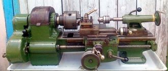
Machine appearance
The Izhevsk plant has provided the ability to connect highly efficient modules even to basic standard equipment; this feature is used during modernization.
The 250ITVM installation is equipped with a function for fixing the head of the cutting tool without clearance. By carving using this technology, maximum rigidity, stability and accuracy are maintained throughout the operation. During thread cutting, the main lead screw is automatically lubricated. Thanks to the unique design of the spindle module, instantaneous change of drive belts is possible, and disassembly of the hub unit is not required.
Machine design and modifications
Appearance
The functional purpose of lathes model IZH-250 is wide. With their help, you can process workpieces using the rotation method. In this case, the part is mounted in a collet, centers or chuck. Additionally, it is possible to form threads of various types.
The design of the equipment is standard, but has a number of features. These include a wide range of gear shifts and cutting tool feeds, the ability to pre-set an operating mode that will turn on in a certain period of time. For ease of control, a mnemonic mechanism is provided. The lead screw is automatically lubricated during thread formation.
In addition, there are several types of machine modernization, which differ in technical and operational qualities, as well as equipment.
- IZH-250ITVF1. Equipped with a digital display unit. With its help, you can significantly increase labor productivity, since the worker does not waste time measuring the actual dimensions of the workpiece;
- IZH-250ITP. Designed for rough processing. This model is produced by special order only.
All types of equipment have a twelve-speed gearbox. High-reliability V-belts are used for drive. The gear block switches when the disks, which have holes for the locking pins, are displaced.
Increasing the accuracy of thread formation is carried out using a vernier mechanism installed on the IZH-250 machine. Additionally, a diagram for connecting the guitar to the lead screw is provided. It allows you to improve processing accuracy.
The machines of this series have gained the greatest popularity for completing production lines specializing in instrument making. This is due to the possibility of individual configuration and changing some machine parameters when ordering from the manufacturing plant.
Device
The passport of the 250ITVM model contains information about the main operating modules of the installation - the drive that provides the rotational torque of the cutter; the second element is the electrical circuit. The latter is used primarily for repair work or as the main means of high-quality installation of additional modules.
Electrical diagram of the machine
The drive operates thanks to a 12-speed gearbox, which allows you to operate at the required speed with the possibility of pre-setting for subsequent start-up. V-belts have an important purpose, which in this unit can be changed without cumbersome disassembly of the main elements.
The smooth gear shift mechanism works according to the following scheme:
- As the flywheel turns, the two selector discs shift.
- Inside the disks, the combination of holes instantly changes, the resulting displacement fully corresponds to the intended gear that the worker wants to engage.
- The holes correspond to locking levers that ensure the required speed is switched.
- The handle is pulled back, which is accompanied by a slight braking of the gears, after which the gear changes.
Machine device
Electrical equipment of lathe IZH250
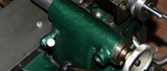
The frame is made by casting, it has reinforcements in the form of a U-shaped rib and is installed on a durable stand. The material for the frame is chromium-nickel cast iron. The bed is equipped with 4 guides (two are prismatic, the rest are flat). The latter are subjected to high-frequency surface hardening and grinding. Inside the cabinet there is an electric drive that rotates the gearbox, an automatic lubrication station and a coolant supply system (cutting fluid).
In accordance with the kinematic diagram of the machine, the gearbox plays the role of a gearbox driven by an electric motor mounted on the flange. To fix the gearbox in the cabinet there is an intermediate bracket.
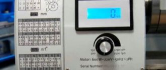
The gearbox has a speed pre-selection device. This procedure is carried out without stopping the machine. The handle turns the flywheel connected to two disks, with the help of which the number of revolutions is selected. The discs form a set of pin holes with levers that flip the gear blocks. To stop the rotation of the gear wheels (up to a speed of less than 100 rpm), this handle is slightly pulled towards itself (a feeling of resistance), and a pause is maintained. Then, with an effort in the same direction (towards you until failure), the gear is engaged. At low speeds, this procedure is done with one movement of the handle.
To make it easier to transfer or change the drive belt (without having to disassemble the entire assembly), its pulley is shifted to the left half of the tailstock housing. The base for mounting the latter is a pin installed at the bottom of the spindle. This element controls the spindle assembly itself in case of heating of the latter and facilitates control of the position of its rotation axis. The rotational torque to the machine spindle comes directly from the pulley or through the selection gears. In front of the headstock body there is a shift knob between the gear coupling and the gearbox. The block will not allow you to turn them on at the same time. To avoid breaking the gears, do not move the handle until the spindle assembly comes to a complete stop. The design of the headstock includes a link that increases the thread pitch.
Using the feed box, thread cutting processes are adjusted or feeds are switched during turning. The size of all transverse feeds is half the size of similar longitudinal feeds. The gearbox rotates the input shaft of the specified box through a replaceable set of gears (thread) or a belt (all other operations). Feed switching at spindle speeds of less than 100 rpm is allowed on the fly. If the speed is higher, then only by coasting (reducing the speed) of the spindle by briefly turning off the rotation on the machine using the provided handle.
The guitar is mounted on the left end surface of the headstock. Due to the presence of blocking, it is impossible to engage the gear drive together with the belt drive.
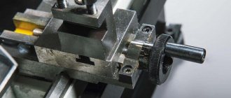
You can lock the tailstock by turning its handle. The clamping force can be adjusted using nuts. An additional screw will contribute to the reliability of the clamp. Grooving short cones on the machine is made easier by the fact that it is possible to move the tailstock body relative to the axis of the machine centers. The displacement is made by no more than + - (10 mm) with a special screw. To control the horizontal position of the axis of the machine centers (relative to the bed guides), the corresponding bosses are aligned on the body and the tailstock tray. The quill is fixed using its handle.
The main functions of the apron include: implementation of the feed movement (longitudinal or transverse) for the caliper through the running shaft; cutting threaded surfaces - from the lead screw. Therefore, the apron is equipped with 4 couplings, which include direct or reverse feeds. These models of machines do not have accelerated cutting of the cutter.
During operation of the machine, the cross-shaped support moves along the workpiece using bed guides, and across it along similar elements of the carriage. Longitudinal movements are carried out manually or mechanically. On top of the caliper there is a main tool holder with four places for the tools. On request, an additional rear single tool holder for the transverse carriage can be supplied.
To cover the cutting zone from flying chips, a protective fence with an opening made of durable transparent polymer was installed. It is mounted using a height-adjustable stand. When cutting workpieces made of brittle material, an additional protective screen is used, which is attached to the main one on the right.
Design features of the structure
The 250ITVM series turning machine has quite unique design drawings. The structure of the machine allows us to highlight a lot of technological features:
- Changes in feed parameters and current spindle speed are made over a wide range, which increases functionality.
- The apron of this model is equipped with a well-thought-out stopping mechanism; thanks to this innovation in the structure, the main elements of the device (gearbox, drive, electrical circuits) are protected from loads.
- The basis for adjusting the spindle operation is preselective control technology. Its essence lies in the advance configuration of this node for the next time it is put into operation.
- The cutting of several thread options is determined not by the sequential change of gears, but by the versatility of the gearbox.
- The resistance parameters of the bed have extremely high numerical values. During manufacturing, the main material for this part is a special grade of chromium-nickel cast iron.
It is possible to regulate feeds on the machine using a lightweight scheme - a special handle is used. The feed direction completely corresponds to the movement of the handle.
Kinematic diagram of the machine
How used is the model today?
Despite the rather “ancient” year of launch into mass production, the IZH 250ITVM passport is still of the old USSR type, but its performance is equal to modern modifications of similar equipment. Today it is supplied to private workshops, school classrooms and secondary construction education institutions without major differences from the original model.
Comparing the design of the machine with alternative multifunctional units, the old IZH 250 loses in many respects, but even such competition cannot completely suppress the demand for these models. The 250ITVM passport does not have superior characteristics, but the accuracy of work on this device can amaze even an experienced modern master of parts processing.
The model lags behind its competitors in terms of ergonomics, number of manufactured parts, lack of computer control and other indicators. But every review of devices capable of thread cutting cannot do without this basic representative of the class.
Operating rules and tips
The kinetic circuit of the device operates stably thanks to a 12-speed 3 kW drive. Speed switching occurs thanks to a flywheel connected to the selector discs. The discs are responsible for the correct placement of holes and levers for a specific gear.
The operation of the handle is very similar in functionality to the operation of the clutch pedal in any car. Before changing speed, the handle is pulled back, which slows down the gears. When the overall speed decreases, the levers of the next gear fall into the pre-arranged holes in the discs and instantly pick up speed.
Note: the operating instructions include an important addition - the machine apron is equipped with a special lock that limits the simultaneous launch of the roller with the lead screw. Likewise, longitudinal movement is blocked if transverse movement of the workpiece is used, and vice versa.
Tips and useful recommendations for effective work on the 250ITVM machine:
- It is necessary to master the functional features and capabilities of each machine model, since in different modifications the same operations are performed by different modules. Care must be taken when considering the types of equipment on which the 5.5 kW drive is installed.
- Connection to the installation network occurs by installing a specialized package-type switch.
- There is a limitation on the power of the electrical network. Standard 220 V networks cannot provide the machine with the required amount of energy. The installation operates exclusively on three-phase 380 V networks.
After purchasing and installing the 250ITVM turning equipment model, the impression of insufficient functionality will not appear. The device is assembled as reliably as possible, which is confirmed by its weight and simultaneous simplicity of design. This “outdated” machine can perform precise thread cutting on small workpieces, while maintaining productivity at a sufficient level.
The only negative is that the model cannot be used under excessive loads and mass production. If processing is performed frequently at maximum speed, any of the main parts of the installation may fail.
Recommendations for operating the equipment
In order for the unit to work efficiently, and for the parts produced to be of high quality and meet the parameters, the machine .
The installation takes place on a specially prepared platform that can dampen vibrations from the load and withstand the weight of the machine.
The final setup of operating modes and rules of use are specified in the instructions included with the machine. Based on the experience of workers with these types of equipment, the accompanying documentation provides a clear procedure and instructions for operating the unit.
Options
machine comes with the following operating parameters:
- With a distance between centers of 75, 100 and 150 cm.
- With the largest turning diameter on the bed – 40 cm.
- With the largest turning diameter on the support – 21 cm.
- With the largest bar processing diameter – 3.6 cm.
- With the longest turning lengths – 65, 90 and 140 cm.
- With a hole in the spindle - 3.8 cm.
- With Morse taper 5.
- With operating speeds in quantity - 21 pcs.
- With working reverse speeds – 12 pcs.
- With longitudinal and transverse feeds in quantity - 35 pcs.
- Modular threads – 10.
- With an electric motor power of 7 kilowatts.
- With a pulley speed of 730 per minute.
- With modular thread size - 3.
Electrical equipment control
The levers of electrical equipment serve as a switch and switch from the network. Workplace lighting is also included. Responsible for the operation of the pump. They control the push-button station to turn the main engine of the machine on and off.
Apron
The apron is responsible for converting the rotational movements of the lead screw or roller into translational movements for the support (feed) along the direction of the bed.
The apron is located in the machine body, as standard facing the supports. Provides rotation of the worm wheel.
Review of the universal lathe IZH250
The IZH-250 machine for turning work was assembled for a long time at the machine-building plant in the city of Izhevsk, and is used in small and large manufacturing enterprises. It was produced in several variations. The main task is to produce an extensive range of turning operations in collet and jaw type chucks. It is also actively used for various types of carving.
Possibilities and varieties
Izhmash engineers tried to modernize the equipment to cover a wider range of work, so they released the turning unit in 3 versions:
- ITPM – specializes in low-precision operations;
- ITVMF1 – model with digital indicators;
- ITVM03 – characterized by an increased center-to-center gap.
To perform turning operations with increased loads, it is recommended to use the 250ITP version of the machine.
The ITVMF1 model, thanks to the digital display, which facilitates the turner’s work in determining the geometric dimensions of the workpiece, is characterized by increased productivity. This modification has a number of other advantages:
- no need to remember the revolutions of the lomb and count some parameters;
- compensation for errors in the interaction of elements;
- reduction of wear of cutting components during operation.
All these processes occur automatically, without the participation of a turner.
The IZH-250 machine makes it possible to carry out various types of threads with high precision, so this unit is in great demand for such activities.
Equipment technical parameters
The lathe has a number of design features:
- equipped with a special mechanism that allows turning and at the same time protecting working units from overloads;
- During operation, the lead screw is automatically lubricated;
- spindle and feed speeds can vary over a wide range;
- to replace belts, the spindle assembly does not need to be disassembled;
- the cutting head is very precisely and firmly fixed, which makes it possible to achieve high precision thread performance;
- changing thread types is done due to the versatility of the gearbox, and not by changing gears.
The machine body is made of a durable type of cast iron, and the guides are ground and hardened using high-frequency currents.
The feed control on the presented turning unit is carried out using a handle and is carried out according to the principle when its movement coincides with the movement of the feed element.
The table shows the technical characteristics of the IZH-250 screw-cutting lathe.
Location of machine controls 250ITVM.01, 250ITVM.03, 250ITVMF1
Location of controls for lathe 250Itvm.01
List of machine controls 250ITVM.01, 250ITVM.03, 250ITVMF1
- Spindle speed selection handwheel
- Spindle speed switch
- Handles for selecting feed rates and thread pitch
- Handles for selecting feed rates and thread pitch
- Handles for selecting feed rates and thread pitch
- Shift knob
- Switching handle for bit and pitch increase link
- Cooling pump switch
- Input switch
- Main switch locking lock
- Digital display for machine 250ITVM F1
- Lubrication station switch
- Button for general stop and emergency shutdown of the machine
- Manual longitudinal feed handwheel
- Manual cross feed handle
- Tool holder fastening handle
- Lead screw nut on/off handle
- Flywheel for moving the upper slide
- Light switch
- Quill clamp handle
- Handle for securing the tailstock on the machine
- Quill movement flywheel
- Nut for securing the tailstock to the bed
- Feed reverse handle
- Start and stop handle
- Safety mechanism adjustment screw
Technical characteristics and design features of the IZH-250 lathe
The IZH 250 lathe is still rightly considered one of the most popular models in its class, despite the fact that it has been produced since the early 60s of the last century.
) provides high build quality and durability. Modified versions have been developed and produced on the basis of this model. Knowledge of its features and technical capabilities will help you correctly evaluate the advantages of the machine.
Differences between modifications
Engineering thought does not stand still, and modified machines have been mass-produced, which have absorbed the best features of the IZH-250, but have also acquired specific features.
IZH 250 ITVM 01 and 03
The machine is distinguished by its increased dimensions of the working space. The center-to-center distance is 700 mm. The diameter of “Shaft” type blanks has been increased to 170 mm.
IZH 250 ITPM
Priority in the machine is given to turning work. Processing class P according to GOST 8–82 is provided. Weight – 1200 kg.
Among the latest modifications, we can highlight the IZH-250 SCI model, equipped with an accurate indication (up to 100 microns in diameter). The machine provides linear compensation for tool wear.
The IZH-250 lathe has been popular for more than 50 years. It is distinguished by fairly high accuracy of parts processing and increased reliability.
Modern modifications are quite competitive with other machines of more recent developments. This equipment can be recommended to both large businessmen and individual entrepreneurs for setting up small production.
What tasks does the unit solve?
The turning, or more precisely, screw-cutting lathe, IZH-250 belongs to multifunctional equipment and is designed to mechanize the work of a turner when working with parts in centers, a collet or a chuck.
It is widely used in the formation of various threaded structures (metric, inch, modular). This equipment is installed both in the workshops of large factories and in the workshops of small enterprises during mass production, production of small batches of products or repair of various equipment.
A sufficient degree of accuracy when working with small-sized parts allows the IZH-250 to be used in instrument making, mechanical engineering and tool manufacturing.
Thread cutting technology on lathes
Installations for automatic welding of longitudinal seams of shells. in stock! Highest performance, convenience, ease of operation and reliability in operation.
Welding screens and protective curtains. in stock! Radiation protection when welding and cutting. Big choice. Delivery throughout Russia!
Methods for obtaining threads
Threaded connections are used in mechanical engineering and construction. The use of threaded hardware allows you to connect device parts and structural elements during construction using bolts, nuts, screws, and studs. Products with threads are also intended for transmitting force or movement in mechanisms such as jacks, gearboxes, presses, and machines .
Scheme of cutting a thread with a tap on a lathe
Jacks and lead screws are made with trapezoidal threads.
There are the following methods for making threads:
- manually (with a tap or die);
- on machines:
- screw-cutting lathe (mod. 16K20);
- thread rolling using rollers and flat dies;
- milling (mod. RTS 161F4) for producing threads with large pitches;
- grinding using wheels with a given profile for the production of small and precise threads;
- screw-cutting (mod. 1622);
- for cutting threads on nuts (mod. 2064);
- providing whirlwind cutting of threads using multi-cutter heads.
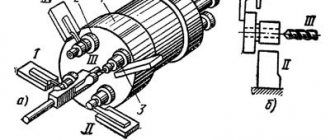
Whirlwind cutting is provided by 4 cutters located in a rotating head, driven by its own motor. This device is mounted on the support of a lathe. Due to the alternate insertion of the cutters, a high processing speed is ensured, since the cutters heat up slightly. This also ensures lower roughness of the resulting threaded surface and increased profile accuracy.
Video of thread cutting on a 1K62 screw-cutting lathe
Decoding the writing of threads
The thread is designated: M12x1.25–7N. This means: metric internal (7H), diameter 12 mm, pitch - 1.25 mm, tolerance range 7H. For external threads, the tolerance field is written: 6h. The coarse pitch value is not given in the designation (M16–8g). The letters LH (M16–8g–LH) are added to the left-hand thread in the designation. GOST 8724–81 provides a table indicating the diameter and pitch of the required size.
READ How to Sharpen a Saw on a Machine
Gearbox
The feed box provides metric, inch, modular and pitch cutting without the use of replaceable gears.
- Thread with metric pitch from 1 to 12 mm (19 steps).
- Thread with inch pitch from 2 to 24 threads per 1 inch (20 steps).
- Thread with modular pitch from 0.50 to 3 modules (10 steps).
- Thread with pitch pitch from 7 to 96 pitches (24 steps).
Caliper
Calipers 1A62, as on other similar models, are responsible for moving the cutting tools relative to the workpieces being processed. The condition of this part of the unit directly affects the precise performance of the work and the functioning of the machine.
The 1A62 support has the following technical capabilities:
- It will mix the longitudinal carriage at 65, 90 and 140 cm, the transverse carriage at 28 cm.
- It has longitudinal and transverse feeds in the amount of 35 pcs.
- The feed is made in the range of 0.082–1.59 mm/rev for longitudinal ones, and 0.027–0.522 mm/rev for transverse ones.
- Cutting thread : metal 19 (pitch from 1 to 12 mm), inch - 20 (pitch - 2-24 threads/inch), modular - 10 (pitch - 0.5-3 modules), pitch - 24 (pitch - 7 –95).
What has a positive effect on work performance:
- Maximum movement increases to 11.3 cm.
- With a maximum movement angle of 90 degrees, and a scale of one division indicates one degree.
- With a maximum holder cross-section of 2.5 by 2.5 cm.
Main technical characteristics
The basic model of a lathe has the following main technical parameters:
- the maximum diameter of the part when installed above the frame (category “Disk”) is 25 cm;
- the maximum diameter of the part installed above the caliper (category “Shaft”) is 12.5 cm;
- distance between attachment points – 50 cm;
- center height – 150 mm;
- standard electric motor power – 2400 and 3000 W;
- total weight of the equipment is 1500 kg.
Processing accuracy class B is ensured according to GOST 8–82.
Purpose and scope
Due to its versatility, 1A62 lathes can be used to produce workpieces with cylindrical, conical and shaped configurations. And cut different types of threads - metric, inch, modular and pitch.
Experienced workers distinguish lathes by just one photo, but more complete information about the machine can be found by looking at the numbers in the name.
- “1” – designation of the group that includes the lathe .
- “A” – designation of the machine generation.
- “6” – designation of belonging to the screw-cutting group.
- “2” – this figure allows you to share the height of the center (above the bed), for this machine it is 22 cm.
Unlike other machines, 1A62 has expanded functionality and improved characteristics.
- Increasing the spindle speed to 1200 rpm, plus the ability to choose from twenty-one forward rotation speeds and twelve reverse ones.
- Installation of a more powerful seven kilowatt engine.
- The main drive of the machine uses reliable wedge equipment.
- The friction clutch of the unit has a reinforced design.
- Installation of a reliable roller bearing in the spindle assembly.
- To prevent spontaneous detachment of the cartridges from the spindle assembly, which occurs when rotational movements in the engine stop, a special groove is provided to accommodate fuses.
- Precise threads are guaranteed by a gearbox with direct engagement of the lead screw.
- The front part of the machine apron has a dial, which is responsible for carrying out longitudinal feed through the support.
- Has a reinforced tailstock.
- The improved design of the tool holder allows it to be rotated in any direction, at any angle, without using the second hand.
- The machine has an improved cooling system, with an electric pump and reservoir located at the rear of the device.
- Installation of steady rests is possible to achieve the required rigidity when using long parts on a 1A62 lathe.
Purpose and design of the tailstock
The tailstock is a device that securely fastens the part when processing in the center or when installing a cutter.
- with a quill diameter securing the cutting tool – 70 mm;
- with an internal landing cone of category “Morse 4”;
- with a maximum movement of 15 cm, with one
- division of the dial quill moves by 0.1 mm;
- with a maximum lateral displacement (in both directions) – 15 mm.
Sources:
https://stanki-katalog.ru/sprav_izh250.htm https://i-perf.ru/stanok/kak-narezat-rezbu-na-tokarnom-stanke.html https://vseostankah.com/tokarnyj-stanok- po-metallu/1a62-tehnicheskie-harakteristiki.html
Design features of the structure
Design solutions provide the following key features of the machine:
- increased gear range and spindle speed;
- automation of lead screw lubrication during thread cutting;
- location of the machine stopping mechanism in the apron, providing a rigid stop;
- securing the cutting tool without gaps;
- preselective spindle rotation control;
- universal gearbox design;
- special spindle design that simplifies the installation and replacement of drive belts;
- high-strength frame made of chromium-nickel cast iron.
Feed control is carried out by one lever according to the mnemonic principle, while the cutting head moves on the support in accordance with the movement of the handle.
General form
Like any screw-cutting lathe, it consists of the following main components and parts: caliper, headstocks (front and rear), gearbox, supporting frame, spindle, gear guitar, running shaft, apron, feed control box, equipment stand, electrical equipment. A screw-cutting lathe (TVS) is distinguished by the presence of a lead screw for cutting threads.
Workspace dimensions
An important characteristic of a fuel assembly is the dimensions of the working space, which determine the maximum dimensions of the workpiece being processed.
The main criteria are the distance between the fixing points of the part (500 mm) and the maximum diameter of the workpiece (250 mm). In addition, it is important to take into account the dimensions of the support and its mounting, which allows you to determine the maximum dimensions of the cutting tool.
List and location of controls
The IZH-250 TVS has a closed apron, with the help of which the caliper moves in various directions manually or automatically. A lead screw is used to cut threads.
Thread cutting on lathes
Thread cutting is a broad topic in metalworking with the introduction of lathes. This development is used in more than 40% of works. The strength of the connection between detachable parts of structures or devices depends on the properties of the threads. Read more about this in the article.
Classification of threads
A thread is a helical line formed on the skin of rotation by the tip of a protrusion of a certain shape. The distance between adjacent protrusions is equal to the thread pitch. The shape of the protrusion depends on its type. There is a depression between two adjacent protrusions.
- Direction of helical mowing line:
- right (it rises from left to right, and the bolt is screwed in a clockwise direction);
- left (screwing occurs counterclockwise).
- Protrusion shapes in the form:
- triangle,
- trapezoids,
- unequal trapezoid,
- rectangle,
- semicircle.
- The outer surface of the part (cylindrical or conical).
- Location on the part (internal or external).
- Number of visits (one, two, three);
- Purpose (fastening and chassis).
- with profile angle:
- 60⁰ (metric, conical inch);
- 55⁰ (cylindrical pipe, conical pipe);
Trapezoidal threads are inherently stronger than rectangular threads, with the least labor required for production. The purpose of a trapezoidal thread is to convert rotational motion into translational motion.
In addition to this, they use a thread called modular. It is used where rotation is transmitted from a worm to a worm wheel, the axes of which are at an angle of 90⁰.
General information
The tip of the cutter, when moving at a constant feed speed along the rotating workpiece, cutting into it, leaves a helical line on its surface (Fig. 4.42).
The inclination of the helical mowing line to the plane perpendicular to the axis of rotation of the workpiece depends on the rotation speed of the spindle with the workpiece and the feed of the cutter and is called the lifting angle μ of the helical mowing line (Fig. 4.43). The distance between the helical lines, measured along the axis of the workpiece, is called the pitch P of the helical mowing line. If a segment on the surface of the part equal to the pitch of the helical mowing line is turned onto a plane, then from the right triangle ABC you can find
where d is the diameter of the workpiece along the outer surface of the thread.
When the cutter is deepened into the surface of the workpiece, a helical surface appears along the helical mowing line, the shape of which corresponds to the shape of the tip of the cutter. A thread is a helical surface formed on rotating bodies and used to connect, seal, or provide data movements of machine parts and devices. Threads are divided into cylindrical and conical.
Depending on the purpose of the threaded connection, threads of various profiles are used.
The thread profile is the contour of the thread section in a plane passing through its axis. Threads with acute-angled, trapezoidal and rectangular profiles are widely used.
cut the M12 thread pitch 1.25 on an IZh 1I611P lathe
Threads are left and right. A screw with a right-hand thread is turned clockwise (from left to right), and a screw with a left-hand thread is turned counterclockwise (from right to left). There are single-start and multi-start threads. A single-start thread is formed by one continuous thread, and a multi-start thread is formed by several threads equidistantly located on the surface of the part. The number of threads can be easily found at the end of the part where the threaded surface begins (Fig. 4.44, a and b).
There are strokes Ph and pitch P of multi-start threads. The stroke of a multi-start thread (GOST 11708-82) is the distance along the mowing line, parallel to the axis of the thread, between any initial midpoint on the side of the thread and the midpoint acquired when moving the initial midpoint along the helical mowing line at an angle of 360° between the same points of the 1st turn of one thread, measured parallel to the axis of the part. The stroke of a multi-start thread is equal to the thread pitch multiplied by the number of starts:
Nuances of operation and passport
The machine should be operated in strict accordance with the equipment instructions. The adjustment must be carried out by a specialist.
- Electrical equipment operates from a three-phase electrical network with a voltage of 380 V.
- Connection to the network is made through a batch and circuit breaker.
- In a number of models in the series under consideration, the speed is not adjusted by the gearbox. To do this, the power of the supplied electrical signal changes. In this case, electric motors of increased power (up to 5.5 kW) are installed.
The feed box provides wide possibilities for varying the feed and thread parameters. To use them correctly, you must use standard lever installation tables. The accuracy of the lateral movements of the tool is increased by the vernier (the accuracy increases to 0.005 mm/rev).
You can download the machine passport for free from the link - Passport of the IZH-250 lathe
Description of the electrical equipment of the EMU-200 machine
Power supply data:
- Mains voltage 380 V, 50 Hz
- Maximum operating current 5 A
- Maximum starting current 20 A
- Rated current of the main fuse / refractory / 10 A
Description of electrical equipment operation
To make it easier to see the connections in Fig. Figure 5 shows a schematic diagram of the electrical equipment of the machine. The network is connected to the RST terminals of the terminal block. The machine is protected from short circuits by fuses. The pump motor and transformer are also protected by fuses.
The on position of the input switch is indicated by a red signal lamp. The auxiliary circuit of the contactor is designed for 24 V, which also powers the signal lamp. This voltage is generated by a 100 VA transformer TM. The transformer is protected from overload by two fuses. It is allowed to use an incandescent lamp up to 60 W, 24 V for lighting.
Starting the drive motor, as well as reversing, is carried out using the reversing switch FJ. The PSZ switch is used to start the coolant pumps.
If the voltage disappears, the motors are started again only if the FJ switch and the PSZ switch have been previously set to the “O” position.
Work, machine and service organs
When the electric motor is turned on, the spindle also starts. The spindle is stopped and reversed electrically by stopping and reversing the electric motor.
The permissible number of spindle reverses is as follows: at 90-130 rpm. spindle 600 reverses per hour, at 140-380 rpm. spindle – 400 reverses per hour.
Spindle speed – Two cases are possible;
- a) Speed 90-480 rpm. In this case, the handle for switching the spindle drive through overdrive or direct drive /18. rice. 8/ turn right. After this, by moving the reversing handle 36 to the left or right, turn on the forward or reverse direction of rotation of the engine and with it the spindle. Only after this is it possible to turn the speed adjustment knob 34 until the corresponding speed value on the spindle speed dial 33 aligns with the pointer,
- b) Required speed 630-315 rpm.
Move the handle for switching the spindle drive through overdrive or direct drive /18/ to the left, and then, after starting the engine, adjust the required number of revolutions.
The right position of the handle corresponds to lower spindle speeds /33/ on the dial, and the left position of the handle corresponds to higher speeds.
The handle for switching the spindle drive through overdrive or direct drive is allowed to be switched only when the spindle is stationary, and the handle for adjusting the speed of rotation - only when the spindle is rotating.
Reversing the spindle is carried out by reversing the motor /switch 36/.
The machine can be stopped so that the switch handle 36 is moved to the neutral position
How used is the model today?
Serial production of the IZH-250 fuel assembly began in 1964, but even today the machine has not lost its relevance. The base model has undergone virtually no changes.
Modern technologies have made it possible to improve the quality of equipment assembly, which has increased the processing accuracy and durability of the equipment. At the same time, the distinctive feature of the machine is its low cost, versatility, ease of setup and operation.