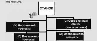
The history of the appearance of a multi-spindle vertical semi-automatic lathe
The appearance of multi-spindle vertical semi-automatic lathes was preceded by a rather long history.
The American Civil War (1861-1865), which created a labor shortage, required automation of production. Then the first automatic machine appeared. K. Vipil created an automatic machine for processing wood back in 1842, and in 1876 Chr. Spencer automated the lathe. His namesake, the English engineer S. Spencer, built his own automatic lathe back in 1860. The multi-spindle machine (in which a product automatically passes through a number of positions and at each of them is subjected to one or more processing operations) appeared in 1895. On the eve of the First World War, automated lathes appeared, on which the workpiece passes sequentially through six to eight positions, and at For each of them, the workpiece is subjected to different turning operations. This machine is known as Bullard's "Multomatic" (Fig. 1). Rice. 1. Bullard's "Multomatic"
Classification of multi-spindle automatic lathes and semi-automatic machines
Multi-spindle automatic and semi-automatic lathes are widely used in serial and mass production. They are divided:
- by type of workpiece - rod and cartridge;
- principle of operation - on parallel and sequential machines;
- spindle location - horizontal and vertical
Automatic and semi-automatic lathes are used for processing workpieces of complex shapes in large-scale and mass production.
A design feature of the machine is the presence of a complete set of mechanisms for performing working and auxiliary moves that automate the cycle, as well as a control system that coordinates their work.
A semi- automatic machine differs from an automatic machine in that the set of automated target mechanisms does not include a loading and unloading device and this operation is performed manually or with the help of additional mechanization. Thus, to repeat the cycle, human intervention is required (for loading workpieces, removing products, orienting, clamping workpieces, starting the cycle)
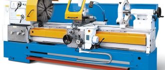
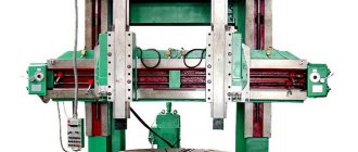
The most widespread are multi-spindle automatic machines and semi-automatic machines of sequential action. On such machines, workpieces from the loading position by periodic rotation of the table (vertical layout) or spindle block (horizontal layout) are sequentially brought to the working positions and simultaneously processed on them by tool groups in accordance with the technological process. Multi-spindle vertical semi-automatic lathes (MVTP) are used for turning cast and stamped medium and large workpieces. The machine spindles are unloaded from bending loads caused by the mass of the workpiece, the machine takes up little space. Modern semi-automatic machines of this type have 4-16 working spindles. The first position is the loading position, the remaining positions contain working mechanisms, and each of these positions can be considered as a machine tool connected to other common drive and controls and the unity of the basic parts.
The peculiarity of MVTP (Fig. 2) is that the operation of spindles and supports in individual positions is independent in their kinematic settings. Compared to horizontal semi-automatic machines, they have the following advantages:
- it is more convenient, easier and safer to install heavy workpieces on the horizontal plane of the chucks;
- occupy a smaller production area;
- all positions in which the part is located during processing are located in places that are easily accessible and convenient for setting up and monitoring the processing process;
- since the spindle speed and support feed in each position are adjusted independently of other positions, processing with optimal cutting conditions can be carried out in all positions;
- For each position, you can install any of the available supports, which expands the technological capabilities of the machine.
Rice. 2. Modern vertical eight-spindle semi-automatic lathe
Automatic longitudinal turning
An automatic longitudinal turning machine is one of the types of specialized turning equipment, included in the classification group “Automatic and semi-automatic lathes”. Such equipment is used in the mass production of high-precision small-sized parts such as rotating bodies. In catalogs of production equipment (especially foreign ones), a different name is used for these machines - “Swiss-type lathe”.
This is due to the fact that lathes with longitudinal movement of the spindle head and a fixed support were created at the end of the nineteenth century by Swiss watchmakers. For more than a hundred years, the basic layout and operating principle of such machines have not changed at all, but at the same time they have received many additional capabilities. Currently, one of the most common types of such equipment is a CNC automatic longitudinal turning machine, which, in addition to traditional fixed supports, usually includes a counter spindle and several positionable blocks of driving and cutting tools.
Vertical multi-spindle semi-automatic device of sequential action
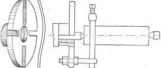
The schematic diagram of a six-spindle semi-automatic machine with sequential action (Fig. 3) includes a base 1 with an installed fixed hexagonal column 5, around which a table 2 with six spindles 3 periodically rotates. Five supports 4 serve five spindles simultaneously. The workpiece is installed in a loading position that does not have a support. After the table is rotated 60°, the spindle begins to rotate and the part is processed in position I. At the end of the first operation, the table rotates again, moving the workpiece to position II, etc. Thus, a certain operation is carried out in each position and, at the end of processing, into the loading The finished part arrives in position. The machine drive consists of an electric motor 7 and a gearbox 6. In general, the machine is composed of three blocks: upper, middle and lower. The upper block contains an electric motor 7 with a gearbox 6 and five gearboxes 8 and feeds, command devices 9, etc.
Rice. 3. Schematic diagram of a six-spindle semi-automatic sequential action
In the middle block, on a hollow column, initially having a prismatic shape, then cylindrical, turning into a cone, components are mounted that determine the accuracy of the machine and its rigidity: guides, supports 4, a rotary spindle table 2 is based. Position drive shafts 10 pass through the cavity of the column, and also a pull rod for the brake and synchronizers 11. On the lower bowl-shaped base block there are synchronizers 13, a brake, a gearbox, a table rotation mechanism and a lock 14, a coolant pump, an electrical cabinet 12, an oil tank and other mechanisms. A rotary spindle table is centered on the hardened conical surface of the column.
Working position command devices are used to control the initial position of the support, control its rapid approach and switch to the working feed and change it during processing, quickly withdraw and control the overload of the support.
The spindle speeds at different positions can be different, and after rotating the spindle table to a new position, the spindle must receive the speed set for this position. For shock-free connection of the gear wheels rotating the spindle with the main drive, a synchronizer is used. The brake stops the spindle, which continues to rotate by inertia, after it has been rotated to the loading position, then releases it, allowing it to rotate when installing the workpiece manually. The spindle table carries spindles with chucks or installation devices and securing workpieces and serves to transport spindles from one position to another. The thrust bearing of the spindle table affects the processing accuracy, reliability of the table and maintaining the position of the spindles under the influence of cutting forces.
The rotation mechanism of the Maltese-type spindle table and the collet clamp ensure smooth indexing and shock-free pairing of the stopper and the table. The table indexing command device is used to adjust the angle of rotation of the table for single or double indexing, determine its position at which loading and processing are permissible, set command points for the end of rotation and turning on the spindles and the clamp, as well as to control the position of the clamp.
Standard calipers allow you to perform the most common types of processing. All main five types of supports are mounted on column guides and provide:
- vertical - vertical movement of the tool, has the simplest and most rigid design;
- universal - longitudinal vertical, and then horizontal or angular movement;
- parallel action - processing of a part by two groups of tools, one of which has vertical movement, and the other - sequentially vertical and horizontal. This support is the least rigid and is used when there is a lack of working positions;
- a support with a drilling head drive - processing off-center holes with planetary heads without stopping the spindle;
- caliper with boring head - finishing of central holes with a diameter of 20 to 100 mm.
Multi-spindle semi-automatic lathes are widely used in large-scale and mass production because they have wide technological capabilities in the manufacture of a variety of parts and provide a high degree of processing concentration. The use of such machines helps to increase labor productivity, reduce machine intensity, reduce production space, and simplify transport connections.
Vertical multi-spindle semi-automatic machines are used for processing relatively large parts in a chuck or fixture, less often in centers. A large number of working positions (usually 6-8) allows them to be used in different combinations. Parts of complex shape are processed at all positions of the machine, moving in the next cycle to the next position (single indexing). For simple parts that can be processed at a small number of positions, more productive parallel-sequential processing is used. There are several options: most often the machine is used as two parallel working machines, turning the table into two positions in each cycle (double indexing). You can process two parts on one side or one, but on both sides, you can process two different parts.
The machines are available in power and speed versions.
Setting the cutting modes—spindle rotation speed and caliper feed speed—is performed by installing replaceable gears and making corresponding switches on the feed boxes. Coordinates for changing the speed and direction of movement of the caliper with an accuracy of 0.3. . . 0.5 mm are adjusted by position controllers using cams. Additionally, rigid stops are used at the end of the stroke. The size of the product is finally adjusted by adjusting the tool.
Specialized semi-automatic and automatic machines
For mass and serial production of similar parts with complex shapes, it is advisable to use specialized semi-automatic machines and automatic machines with high productivity. For example, automatic and semi-automatic lathes are used in the mass production of complex-shaped parts from rods and piece blanks. Parts are processed on these machines using several tools, which are installed in drilling, threading and other devices. The main disadvantage of these machines is the lengthy setup of equipment when switching to a new type of part, which requires alteration of the main components.
A classic example of special machine equipment is an aggregate semi-automatic machine and an automatic machine, in which the use of multi-tool and multi-position processing makes it possible to increase productivity tens of times compared to universal equipment, including CNC.
To reduce costs, special machines are not designed anew each time, but are assembled from ready-made functional elements for general purposes.
In multi-position modular semi-automatic machines, power heads and power tables, guides, rotary tables with frames and a periodic rotation drive, side beds and vertical stands, control equipment units and drives are normalized. Only spindle boxes and devices for securing parts are designed. The remaining parts are selected from catalogs, just as bearings, engines, fasteners, etc. are selected.
The layout diagram of multi-spindle semi-automatic machines is shown in Fig. 114.
Let's take a closer look at the operating diagram of a six-spindle sequential automatic machine (Fig. 115, a
).
The machine has six spindles 6,
located at equal distances along a circular arc in one spindle block
1
.
There are six transverse supports 2 around the block,
and
5
, common to all spindles, moves 4. It is made in the form of a hexagon, on each face of which holders with a tool are installed.
Transverse calipers receive feed from individual cams, and longitudinal calipers - from one common cam. If necessary, sliding holders with a cutting tool can be installed on the longitudinal support, receiving feed from individual cams, and nearby there are tool spindles with an independent rotation drive. The spindles of the machine receive rotation from the drive shaft 3
through a common central gear
7
and therefore have the same number of revolutions.
Rice. 114. Layout diagram of multi-position semi-automatic machines from normalized elements
Rice. 115. Scheme of a six-spindle machine mod. 1A225-6:
A
— workpiece processing scheme;
b
- layout of the machine
Multi-spindle bar automatic machines mod. 1A225-6 and MP-32 are designed for drilling, countersinking, threading, rolling and cutting parts made of rod material with round and multifaceted cross-sections. The high rigidity of the machine's design allows it to process workpieces at high cutting conditions with tools with carbide inserts.
Automatic (Fig. 115, b
) consists of a frame
16
on which all units are fixed.
Inside the frame there are electric motors of the main drive, a cooling system pump and a screw conveyor for removing chips, a gearbox 11,
a spindle block
housing
5 6
and a longitudinal
8
caliper, a longitudinal support drive and devices, a handle for turning on the automatic cycle
12.
The control includes a remote control control 14,
square
15
for turning the conveyor off and on, square
13
for switching speeds, cycle indicator
9
on body
10.
The workpieces are inserted into guide pipes
2,
which are mounted in
the rear disk
1
and the middle disk
3
17. The workpiece is processed in the machine automatically in six spindles placed in one periodically rotating spindle block located in housing 5
with ribs
4.
The cutting tools are installed in several transverse supports
6
located around the circumference of the spindle block and on a longitudinal support
8
. The machine is controlled by a camshaft located in the traverse 7.
Push-button control is located on the control panel
14.
The automatic operating cycle of the machine is activated by handle
12,
and the rotation speed of the spindles is changed by square
13.
The chips are removed by a screw conveyor, which is turned on by square
15.
The machine has a mechanism for automatically stopping the movement of the rod, a counter of processed parts, and a screw conveyor to remove chips, which ensures trouble-free operation and facilitates maintenance of the machine. It is also equipped with a quick adjustment camshaft drive.
Modular machines made from normalized units have found wide application. In aggregate machines, various schemes for processing parts are used.
In Fig. 116 shows the arrangement of power heads for the case when the part is stationary, and its processing occurs in one or two installations with a combined cutting tool. Use double-sided corner ( a
) arrangement of power heads, three-sided (
b
), four-sided (
c
) and circular (
d
). With the first three options, the workpiece can be fed in the same plane of the power heads, and with a circular arrangement, the workpiece can be fed from above with a beam crane or from an inclined magazine.
Rice. 116. Layout of aggregate power heads:
A
- angular;
b
- tripartite;
c
- four-sided;
g
- circular
If during processing the workpiece occupies a number of sequential positions, then a row (Fig. 117) arrangement of power heads is used. There are modular machines with one-sided ( a
) and double-sided (
b
) arrangement of power heads, equipped with a transport system with rotary tables.
The processing diagram for a body-type part is shown in Fig. 118. The part is stationary and processed in one setup.
Rice. 117. Location of power heads:
A
- one-sided;
b
- bilateral
Rice. 118. Processing of body-type parts
Let's consider the application of this scheme using the example of a typical layout of a specialized aggregate machine for processing brackets (Fig. 119). All components and elements of the unit can be divided into: group of supporting elements - bed 1
;
horizontal brackets 13, 14, 15, 16
and vertical
5, 7
;
rotary dividing table 2,
a group of gear elements - power heads
4, 6, 8
of the GS-5 type;
power heads 10, 13′
type GS-7;
gearboxes 11
,
14′, 9
and table drive gearbox;
group of control elements - stops and remote control 3.
Typically, the layout of the unit includes loading and unloading devices, a chip conveyor and a cooling system.
Rice. 119. Typical layout diagram of an aggregate machine for processing a bracket
The workpiece-bracket is installed on the loading position 12
dividing rotary table
2
and secured in the device.
The machine's operating cycle is automatic. The dividing table is rotated and the workpiece is placed in working
position
I. At this position, holes are drilled on one plane, then the part moves to working position II,
where the drilled holes are countersinked.
When the part arrives at position III,
the second group of holes is drilled, and at position
IV
, holes are drilled on a plane perpendicular to the first.
At V
, the holes drilled at position
IV
countersinked.
As a rule, the productivity of modular machines is high, and their design allows processing parts of complex shapes such as cabinets. Power multi-spindle heads are installed on aggregate machines. The layout of the machine is similar to the machine in Fig. 119, is an aggregate five-sided 20-spindle horizontal drilling machine. This unit performs drilling, countersinking, facing and reaming of holes in trapezoid rods and steering link ends.
The table layout includes a seven-position rotary index table, on which seven fixtures are installed for clamping four parts. Five horizontal power heads installed on the frame ensure the processing of parts. The parts are unloaded by a mechanism, the parts are clamped hydraulically, and chips are removed by a conveyor with a lift to a height of 1000 mm. When processing a part, a cooling emulsion is supplied, the machine’s operating cycle is automatic.
Rotary machines are included in a special group of devices. This group of machines makes a continuous circular movement together with the product and performs all technological operations during the movement. The main property of machines is that their productivity does not depend on the duration of technological operations. Products are transported from one working machine to another by rotating rotors. In Fig. 120 shows a diagram of a rotary machine.
Rice. 120. Scheme of a rotary machine
The process rotor consists of a transport feed rotor 1,
removable rotor conveyor
13,
processing (working) rotor
14
with shaft
3,
sliders
4, 11,
gear transmission wheels
5, 6, 7,
blocks
10.
The loading transport rotor consists of hoppers, trays, and orientation mechanisms. The loading rotor ensures the delivery of processed items to the position of the processing rotor. Preparation in zone 11
from the loading conveyor of rotor
1
is fed into the working rotor
14,
sitting on shaft
3.
In zone
I
, when the working rotor rotates, the workpiece is processed, and in zone
IV
it is removed by the transport removable rotor
13
using load-bearing bodies
2
and
9.
The load-bearing bodies
2
and
9
are driven in rotation by gear wheels
5, 6, 7.
In zone
III
, tools are changed, which are mounted on blocks
10.
When the rotor rotates, the blocks are moved by sliders
4, 11
under the action of stationary copiers
8
and
12.
The rotor diagram of the cold stamping line (Fig. 121) consists of press rotor 1
, transport rotor
2,
electrical probe
3
and control rotor
4.
Rice. 121. Scheme of a rotary machine for cold stamping
Auto operators
Automatic operators are mechanisms or a set of mechanisms that ensure the supply of a workpiece to the working area of the machine and the removal of the processed part.
The auto operator includes the following devices: cutter, feeder, gripping mechanism, pusher, ejector or puller, discharge and blocking devices.
Several types of these target mechanisms have been discussed previously. Of interest is the auto operator, who ensures: movement of the part from the magazine to the machine along a complex trajectory; rotating the part 180° to process sequentially first one and then the other surface.
The auto operator can be an attached, independently operating mechanism (Fig. 122). It is attached to the frame with screws passing through the holes in the plate 6.
Lever
2
with vacuum (pneumatic) grip
1
can swing in a vertical plane relative to axis
3
located on bracket
4,
which rotates 360°.
Pneumatic drive 5
transmits movement to lever
2
and bracket
4
from the camshaft, command device, sensor and time relay.
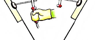
In Fig. 123, a shows diagrams of the work of the auto operator for moving flat planes, and in Fig. 123, b
- cylindrical parts. Some auto operators also use a mechanical (tweezers, several spring wires) or electromagnetic gripper. In pneumatic (air) grippers, ejection occurs under the action of the part’s own weight or by supplying air under pressure after turning off the vacuum, as well as mechanically.
Products of complex shapes that require a complex trajectory of movement during removal are carried out using mechanical arms.
Rice. 122. Universal mechanical auto-operator arm
Rice. 123. Schemes of action of auto operators
An example of an auto operator with a tilter is shown in Fig. 124. The work cycle of an auto operator occurs as follows. In the initial position, the mechanical arm 3
is retracted to the left and its grippers are located coaxially with the spindles of loading positions
I
of the machine.
After turning the spindle block, the hydraulic cylinder 9
of the axial movement of the mechanical arm
3
moves it towards the spindles.
The upper grip 7
clamps the finished part, and the lower grip clamps the semi-finished product.
Next, the mechanical arm 3
moves to the right and rotates from the hydraulic cylinder
9,
stopping in position
III
.
After turning, the mechanical arm moves to the outlet tray 4
and the tilter.
The fully processed part is fed into the outlet tray, and the semi-finished product into the tilter 5.
Then the mechanical arm moves back and turns to position
II
.
At this time, feeder 2,
together with the workpiece, moves to the loading position, and the tilter turns the semi-finished product 180°.
The mechanical arm moves towards the tilter, and its upper grip picks up the workpiece, and the lower grip picks up the semi-finished product. Then the mechanical arm moves back again, rotates to position I
, feeds the workpiece and semi-finished product into the spindle chucks and moves back to its original position.
feeder 2
moves up to tray
1
.
The cutter 6 is activated,
passing a new workpiece from the tray into the feeder. Then the work cycle is repeated.
Rice. 124. Automatic operator with a tilter for a multi-spindle automatic machine
In recent years, numerous designs of auto operators with a large number of degrees of movement - manipulators - have become widespread.
Kinematic diagram of a vertical multi-spindle semi-automatic machine of sequential action
The kinematic diagram of one of the seven sections of the main movement and feed drive (the other six sections are similar), as well as the drive and mechanism for rotating the table with spindles is shown in Fig. 3 33
During the main movement, the working spindles VIII receive high rotation speeds from the electric motor M1 (N = 10 kW; n = 1460 min-1) through the gear 16-39 • 39-118 • 118-31, and low speeds through the gear 16-39 • 22 -39 • 22-39 • 39-118 • 118-31 and further from shaft V through replaceable wheels ab, cylindrical pairs of wheels 35-40 and 37-50 (for high-speed versions - through a pair of wheels 37-37). A gear wheel with z = 35 during table rotation is disengaged from a wheel with z = 40, and after rotation it engages with the same gear wheel of another spindle that has come to this position. After each indexing of the table, the spindles acquire the rotation speed of the position in which they crossed. The rotation speed of the spindles in each position is regulated by its own setting link a - b. Synchronizers ensure a smooth, shock-free start of rotation of the spindle in each position. Each spindle, starting with shaft V, has an individual drive chain, but identical with the chains of other spindles. There are as many of these chains as there are working positions (the 1K285 machine has seven of them). The brake that stops the loading position spindle has a mechanism that is activated by a drive common with the synchronizers, engages with the conical cups of the pre-spindle shafts and is similar in design to the synchronizer, but has no rotating elements.
Rice. 4. Kinematic diagram of a vertical multi-spindle semi-automatic lathe model 1K285
The chains of working feeds and rapid movements of the caliper are concentrated in the feed boxes. Using electromagnetic friction clutches built into them, the feed speed is switched from high to low or vice versa (in a ratio of 2.63 times).
The working feed of the calipers is carried out from shaft VI through the worm gear 1-32, a set of replaceable gears cd e-f and then through gears 35-62 (when the electromagnetic clutch EM1 is turned on) or through wheels 58-39 (when the electromagnetic clutch EM2 is turned on ) on shaft XIII. From this shaft, through bevel gears 27-38, rotation is transmitted to the caliper lead screw nut (P = 12 mm). By switching the EM1 and EM2 clutches, you can automatically set two working feeds of the support (small and large) during the processing of the workpiece.
Accelerated feed of the support is carried out from shaft V through bevel gears 20-20 and a pair of cylindrical wheels 70-40 to shaft X. Further, with accelerated supply of the support to the workpiece (electromagnetic clutch EM3 is turned on), rotation is transmitted through gear 57-39 • 38-59 • 27-38 on the caliper lead screw nut. With accelerated retraction of the caliper (electromagnetic clutch EM4 is turned on), rotation is transmitted to the lead screw nut through gears 58-31 • 31-38 • 38-59 • 27-38. In the rapid feed chain, it is possible to reverse the direction of movement by switching on different kinematic chains using two clutches.
Electromagnetic fast-speed clutches of the caliper are interlocked with the same working feed clutches. The clutches are activated using limit switches installed in the control device.
The rotation of the command apparatus shaft is carried out from shaft XIII through a helical gear drive 18-13 and a worm pair 1-66. The command device controls the working and auxiliary strokes of the caliper in the automatic and adjustment cycles. In addition to the limit switches, its body contains a cam shaft and levers. Limit switches do not have springs, which is why the command given to them is remembered until the next press.
After completing the working operations in all positions and retracting all the supports to the upper position, a command is given to turn off the drive of the electric motor M1 and braking the entire system, followed by rotation of the table.
The table is rotated by the M2 electric motor (N = 2 kW; n = 1300 min-1) through a 1-25 worm gear, 14-105 gears and a Maltese cross. A bar with two rollers is installed on the hub of a gear with z = 105. When you turn the wheel with the bar, the rollers fit into a groove on the bottom of the table, turning it. When the bar is rotated 180°, the table rotates one position (1/8 of a turn), and when rotated 360°, it rotates by two positions at once (1/4 of a turn). After the table is rotated, but before the spindles turn on, it is locked.
The table rotation and fixation mechanism is controlled by the action of two cams 2 on the limit switches of the table indexing command apparatus. The cams are mounted on shaft XXII, which receives periodic rotation through gear 105-15 • 4-28.
At the end of the table rotation, the electric motor M2 is turned off and the starting clutch of the main drive motor M1 is turned on.
The machine is equipped with an automated hydraulic device for clamping the part, has a mechanized loading device and a chip removal system. The machines in the six-spindle version are available with chuck diameters of 630 and 800 mm, in the eight-spindle version - 250 and 400 mm.
In addition to the five types of supports already mentioned, special supports can be supplied with the machine upon request, which are a modification of the universal one and allow you to expand the technological capabilities of the machine - to perform:
- processing of longitudinal shaped surfaces using a copy machine;
- processing cones using a cone ruler;
- processing of cylindrical surfaces with rebound at the end of the working stroke;
- machining the end surface simultaneously with the conical surface;
- boring of spherical surfaces
Among the various devices that are equipped with a semi-automatic machine, the most complex is the kinematic chain of the drive of a multi-spindle drilling head. When the head is used, an additional gearbox is attached to the feed box of the corresponding position.
Parallel action semi-automatic devices
Parallel-action semi-automatic machines are also designed according to a similar scheme, on all spindles of which, unlike sequential-action semi-automatic machines, identical operations are performed simultaneously and in one cycle of work the processing of as many workpieces is completed as the number of spindles the machine has. Such a machine has a base 5 (lower block) installed a fixed vertical column 4, around which a table with spindles and a hexagonal sleeve with six supports 2 continuously rotate, representing a single whole - carousel 1 (Fig. 5).
Rice. 5. Scheme of operation of a vertical multi-spindle semi-automatic machine : 1 - carousel; 2 — caliper; 3 - drum; 4 - column; 5 - base.
When the liner is rotated, the calipers move along its vertical guides from the stationary drum 3 (upper block), with which they are connected by rods. In a semi-automatic machine, each spindle has its own support, from which the part is processed while the carousel rotates. In one full revolution of the carousel, each spindle passing through the loading zone completes the processing of the part. In this zone, the spindle rotation is first automatically switched off and the part is released from the clamp, and the corresponding support quickly moves up, the finished part is removed and a new workpiece is installed. Then it is automatically clamped, the spindle is given rotation, and the support is quickly brought to the workpiece. Modern semi-automatic machines of this type have four or more working spindles.
Multi-spindle horizontal automatic and semi-automatic lathes
An automatic machine, in which several tools are brought to the product in a certain sequence automatically, and the turner only feeds bar blanks, was created in the years.
American Civil War (1861-1865) and put into production a few years later.
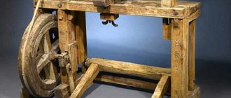
The first multi-spindle horizontal automatic machine mastered in the USSR at the machine tool plant named after. S. Ordzhonikidze in Moscow in 1936, there was an automatic machine model 123. Subsequently, a multi-spindle vertical semi-automatic machine model 23 was mastered in Moscow (1937) and a multi-spindle horizontal automatic machine model 1261 at the Kiev Machine Tool Plant (1939). The first machines of this type had the appearance shown in Fig. 6.
Classification of multi-spindle horizontal automatic and semi-automatic lathes
Multi-spindle horizontal bar turning machines are produced for processing bar blanks or pipes with a diameter of 16 to 160 mm. The design of the machines is made taking into account the possibility of integrating them into automatic lines. Six- and eight-spindle machines, unlike four-spindle machines, can be configured to work with double indexing.
For broad unification, the range of multi-spindle horizontal automatic machines is built according to the following scheme:
- the largest sizes of processed bars are selected for each type of machine according to a geometric series with a denominator of 1.58;
- six-spindle machines are basic;
four- and eight-spindle machines are produced on the basis of basic models with minor changes determined by a different number of spindles;
- in eight-spindle machines, the distance between the spindles is smaller, as a result of which the processed rod is 1.26 times thinner than in six-spindle machines, and in four-spindle machines, on the contrary, it is 1.26 times thicker.
Rice. 6. Schutte four-spindle automatic machine produced in 1915 (Germany)
Multi-spindle horizontal bar lathes are available in bar and cartridge versions for operation in large-scale and mass production. In the cartridge version, the machine is optionally equipped with an auto operator to automate the loading of workpieces and unloading of processed parts. The rod-type machine is equipped with a device for supporting rotating rods, the front ends of which are located in the spindle block and secured in the spindles using collet chucks. Semi-automatic machines based on the same element base process piece workpieces with a diameter of up to 500 mm.
Classification of automatic lathes
Automatic and semi-automatic lathes are a separate group of turning equipment designed for high-speed mass production of small-sized cylindrical parts. One of their characteristic features is that many types of this equipment use a calibrated rod or wire as a workpiece, fed into the processing zone through a hollow spindle. The main types of materials processed on these machines are ordinary and alloy steels, aluminum alloys, brass and other copper alloys.
Classification of automatic and semi-automatic lathes is made according to the following criteria:
- scope of application (specialized, universal);
- layout (vertical, horizontal;
- number of spindles;
- principle of feeding and fixing the workpiece;
- type of control (mechanical, electromechanical, electronic with digital drive);
- processing method;
Within classification groups, additional features related to technological features, purpose and types of processing are used. Therefore, single-spindle semi-automatic lathes, simple cam lathes and machining centers with longitudinal turning have identical names, which differ only in the type of control and additional equipment. For example, the full name of one of the groups of modern automatic longitudinal turning machines according to this classification may sound like this: “universal horizontal single-spindle bar longitudinal turning automatic lathes with CNC, counter-spindle and turret head.”
The additional spindle of a longitudinal turning machine is classified as additional equipment, therefore, taking into account the presence of a turret head, it can also be called a “single-spindle lathe-turret longitudinal turning machine.”
A multi-spindle automatic lathe is a machine with a spindle unit consisting of several parallel spindles, which is mounted in the headstock. The total number of spindles in such equipment is from two to six. Two-spindle machines are rare, but the most common is the six-spindle automatic lathe.
In such a lathe, the number of stationary supports with cutters arranged in a circle corresponds to the number of simultaneously rotating spindles. When the block is rotated, each spindle with a workpiece clamped in it moves to the next position to the next support. Each support has different cutters that perform turning on a specific surface of the workpiece. Thus, for six fixed positions of rotation of the spindle block, each of the six parts is processed by different cutters of six supports.
The device of a horizontal multi-spindle lathe
The main components of the machine are the frame 3 (Fig. 7), on which the spindle block housing 4 is mounted on the left, and the feed box housing 8 on the right. The spindle block itself, the mechanism for fixing the spindle block, clamping and feeding the rod are located in the spindle block housing, and also a stop mechanism (in bar-type machines).
Rice. 7. General view of a six-spindle horizontal lathe : 1 - supporting device; 2 — chip unloading tray; 3 - base; 4 — spindle block housing; 5 — transverse support; 6 — longitudinal support; 7 - traverse; 8 — feed mechanism housing; 9 - electrical cabinet.
The feed box contains drives for rotating the working spindles and the camshaft, mechanisms for threading, quick drilling and reaming, as well as drive bushings. On top of both housings there is a cross-beam 7, inside of which there is a camshaft with drums and other devices. On the end surface of the spindle block body, facing the inside of the machine, and on the traverse, there are transverse supports 5. On a pipe fixed in the feed box body and in the center of the spindle block, a longitudinal support 6 is mounted in the form of a multifaceted prism, on each face of which tools and equipment are installed for servicing spindles On the edges of the longitudinal support serving the fifth and sixth positions, movable racks can be installed for tool spindles that have a movement independent of the movement of the main longitudinal support. Tool spindles are used for thread cutting and fast drilling.
The bed is the base of the machine. To increase the accuracy of the machine, its body components - bed, spindle block, gearbox, traverse - are interconnected and form a rigid frame (portal). In the recess in the middle part of the bed, where chips are collected, and in tray 2, a screw conveyor is placed to remove them.
The spindle block contains a spindle drum, a mechanism for fixing and lifting the drum, a mechanism for feeding and clamping a bar, and drives for transverse supports of the 2nd, 3rd, 4th, and 6th positions. Six spindles are located evenly around a circle with a diameter of 320 mm. Inside each spindle there is a feed and clamping collet. The mechanism for turning and fixing the spindle drum begins to operate after the rod is fed and clamped in position 1.
A semi-automatic machine, unlike an automatic machine, processes piece workpieces. Because of this, it is deprived of a supporting device, and the spindles of the machine do not have a mechanism for feeding the bar workpiece. In an automatic machine, processing cycles are repeated without the participation of a worker, and in a semi-automatic machine, the machine operator must, after finishing the processing cycle and stopping the spindle in the loading position, remove the processed workpiece from the chuck, insert unprocessed and turn on the processing cycle.
Multi-spindle machines
This equipment is divided into two types:
- parallel action;
- sequential action.
The camshaft is a characteristic part in semi-automatic and automatic lathes.
Cams of various shapes and designs are mounted on it (depending on the purpose). They control all auxiliary and working movements of machine tools through a system of mechanical and other connections. The most commonly used cam designs are:
- drums _ They are designed to control auxiliary and working movements of machine tools. It is a cylinder that is equipped with overhead cams or shaped milled grooves;
- disk _ They are needed to set the working parts of semi-automatic and automatic machines in motion - calipers and turrets.
Discs with end-mounted cams are used only to activate auxiliary movements (rotation of the turret, clamping and movement of the rod, etc.). The discs have a separate scale. Most often it is divided into hundredths of revolutions. This scale is necessary to install the cams in the right place.
Multi-spindle horizontal
They are needed for processing elements from calibrated rods of hexagonal, square and round profiles, as well as from pipes in mass and large-scale production of various branches of mechanical engineering.
The main technological operations performed on this equipment are:
- shaped turning;
- thread rolling;
- segment;
- thread cutting;
- deployment;
- drilling;
- grinding.
All necessary movements in the equipment occur automatically with the help of cams, which are located on the camshaft. With one revolution, a full range of movements of the device mechanisms occurs , which is necessary for the production of one processed element. This complex determines the processing cycle, and the cycle time is the period during which one revolution of the camshaft is made.
In a multi-spindle horizontal bar device, the spindles are arranged in a spindle block along a circumference. Transverse supports are located at the end of the spindle block, and the longitudinal support can move on the central sleeve. The spindles of the device receive rotation from the central shaft through gears. After the finished product is cut, the spindle block is rotated at an angle that corresponds to the number of spindles.