Workpiece processing scheme
Figure No. 1. Scheme of part processing. Designation of device elements: 1 - drive cartridge; 2 – fastening leash-clamp; 3 – fixing bolt; 4 – movable steady rest; 5 – product being processed.
Lathe driver chucks used in turning work are made in the form of a disk with four grooves and a threaded bushing having identical dimensions to the headstock spindle. When using a straight clamp, a movable pin is installed in the cartridge, fixed with a nut in the groove of the fastener. When processing the workpiece, the pin rests against the tail of the clamp. The cartridges used must comply with GOST 2571-71, GOST 13364-67, GOST 1435-99 and GOST 25557-2006 for all established parameters.
Download GOST 2571-71 “Drive-type lathe chucks”
If a curved clamp is used during a turning operation using a lathe, the pin is not used, since the tail of the clamp is installed in the groove of the locking element.
Drawing No. 2. Drive chuck design. Designation: the main elements that make up the fastening element of the workpiece being processed.
This design has protruding parts, which allows the possibility of injury to the specialist processing the product. To eliminate the possibility of injury, a closed cartridge is used, made in the form of a casing with a boss and a threaded sleeve identical to the open element. The clamp is hidden inside the casing, which ensures safe work.
Drawing No. 3. The design of the driving chuck, made with a closed body. Designation of elements: 1 - cap with tide; 2 – outer sleeve; 3 – clamp.
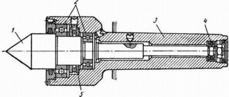
Fastening elements that do not provide for the use of a clamp are also used. In order to speed up the processing of products, instead of clamps, front centers are used, which simultaneously perform two operations: centering the workpiece and acting as a leader (Drawing No. 4). When the product is exposed to the rear center, the corrugated notches are pressed more tightly to the sides of the part and impart a rotational movement to it. When turning hollow products, external grooved centers are used, and when using rollers, internal grooved centers are used.
Drawing No. 4. Fixing the workpiece using a driving chuck. Designation: 1,2 – centers.
The workpiece to be processed is supported on the center, and the cams are used to transmit rotation to the workpiece. Moreover, the cams are made floating for more complete fixation of the part. The mandrel is fixed using the clamping force acting between the tailstock and the front center of the lathe mechanism, which moves to the left, as a result of which the cams take the optimal position and fix the workpiece more tightly. The conical support ring has a gap, which allows it to occupy a middle position due to springs. Rotational movements of the workpiece are ensured by cams with a grooved surface.
Safe and dangerous leash cartridges
Purpose.
The self-centering three-jaw lathe chuck belongs to the class of spiral-rack self-centering three-jaw chucks with a cylindrical belt and mounting on a lathe through an intermediate flange. Self-centering spiral rack lathe chucks are designed for installation on universal lathes, turrets, and internal grinding machines. They are used in conditions of single, small-scale and mass production. Three-jaw self-centering chucks hold round and hexagonal workpieces or round rods of large diameter. Unlike wedge-type lathe chucks, they do not require time for readjustment in the case when installation to a different clamping diameter is required.
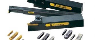
Serrated and pin driver chucks
To process shafts, when the use of machines is necessary, gear and pin drive chucks are used, transmitting rotation of the part through the end with the ability to process the side surface.
Set of serrated driver chucks
The part is processed at the front of the floating center, transmitting rotational motion with the possibility of deflection. This type of fasteners provides reliable fixation in the axial direction, allowing for high-quality processing.
Main design options
Lathe chucks are made of durable cast iron with a grade of at least SCh-30 or tool steel grades with a strength of at least 500 MPa.
There are various design options for lathe chucks; we will focus on the most commonly used in modern production:
Lever chuck. The clamping occurs due to the displacement of the cams with clamps due to the action of a two-arm lever. The main characteristic is the number of cams and the degree of displacement on the working disk. The disadvantages include the difficulty of setting up, especially when carrying out non-standard operations. The cams can be adjusted by moving them simultaneously using a key or by individually adjusting each clamp. This type of equipment is usually used for roughing or semi-finishing.
Wedge lathe chucks are an improved version of the lever clamp design. High accuracy of fixation is ensured by the presence of its own mechanical or pneumatic drive for each cam. It has the ability to fix the workpiece with an offset relative to the center of rotation, which makes it possible to process parts of complex configurations.
Diaphragm lathe chucks. Provide the highest fixation accuracy thanks to membranes made of elastic material. The workpiece is fixed by turning off the hydraulic drive, which leads to expansion of the membrane. Characteristic features of the design are a large number of clamps with a relatively low compression force. Therefore, the main area of application of this type of equipment is finishing of parts at low rotation speeds.
Clamping mechanism design
Another important classification of devices, affecting their design and application, concerns the assembly of the clamping mechanism. According to this parameter, chucks for lathes are divided into the following types:
- Drivers are the simplest, used for processing the center; if it is necessary to sharpen the side surfaces, gear and pin units are selected;
- Spiral self-centering - centering occurs simultaneously with fixation, which reduces the time required for preparation. The most popular lathe chucks are equipped with two, three or six holders;
- Lever - their feature is the presence of a rod with a coupling, driven by a hydraulic drive. Due to this, fastening occurs. In demand in small-scale production;
- Wedge rack - this lathe chuck is similar in characteristics to a lever chuck, but provides greater centering accuracy;
- Collet - capable of fixing only rod samples with a small diameter. Despite the low versatility, they are popular due to minimal radial runout, which improves the quality of work;
- Drilling - designed for connecting drills and other tools to the machine;
- Thermal chucks - used on the same machines as collet chucks, but they require a shrink fit to connect the tool;
- Hydraulic chucks are another alternative to collet devices. The lathe chuck clamps the tool due to the operating fluid pressure, which reduces the force required for reliable clamping.
GOST 2675-80 SELF-CENTERING THREE-JAW CHUCKS
1. The standard applies to self-centering spiral-rack three-jaw chucks of accuracy classes N, P, V, A, installed on machine spindles through adapter flanges and directly on the flanged ends of the spindles.
2.Cartridges must be made of the following types:
Type 1 - with a cylindrical, centering belt and with fastening through an intermediate flange in accordance with GOST 3889-80.
Type 2 - with fastening directly to the flanged ends of the spindles under a rotary washer in accordance with GOST 12593-72;
Type 3 - with fastening directly to the flanged ends of spindles in accordance with GOST 12595-85.
1, 2. (Changed edition, amendment No. 1).
3. Cartridges of all types are manufactured in the following versions:
- with solid cams,
- with assembled cams.
4. The main dimensions of cartridges of types 1, 2, 3 must correspond to those indicated in drawing 1 and table 1.
An example of a symbol for a type 1 chuck, 200 mm in diameter with solid jaws, accuracy class H:
Cartridge 7100-0007 GOST 2675-80
The same, type 2 chuck with a diameter of 200 mm, mounted on a spindle with nominal size 5, with prefabricated jaws, accuracy class P:
Cartridge 7100-0032-P GOST 2675-80
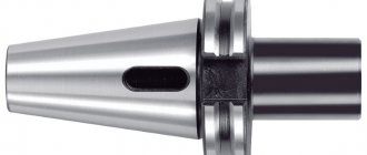
Thermal cartridge
Thermal chuck is used for the same purposes as a collet chuck. The difference lies in the principle of clamping the tool: a shrink fit is used for this in the thermo-chuck. The cartridge is heated in a special device, and its hole increases due to thermal expansion. Then the tool is inserted into it, and the cartridge is cooled (in air or in a special device). Unclamping occurs in a similar way.
The advantage of a thermal chuck is its high clamping force, which cannot be achieved in a collet chuck, much less a drill chuck. The use of such a chuck reduces vibration and significantly increases the durability of the tool.
Disadvantages: tools of different diameters require different chucks; constant cycles of heating and cooling lead to severe wear of the cartridge; Special equipment is required to change tools.