GOST 18877-73
GOST 18877-73 Group G23
INTERSTATE STANDARD
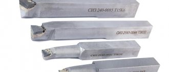
LATHE CUTS, PASSING, BENT, WITH CARBIDE ALLOY PLATES Design and dimensions Carbide-tipped bent bull-nose turning tools. Design and dimensions
ISS 25.100.10
Date of introduction 1974-07-01
ENTERED INTO EFFECT by Resolution of the State Committee of Standards of the Council of Ministers of the USSR dated June 8, 1973 N 1429 The validity period was removed by Decree of the State Standard of the USSR dated 02.20.81 N 866 INSTEAD OF GOST 6743-61 in terms of type 1; MN 575-64; MN 576-64; MN 5199-64 EDITION with Amendments No. 1, 2, approved in February 1981, November 1984 (IUS 5-81, 2-85), Amendments (IUS 6-88, IUS 4-89)
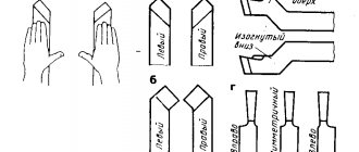
1. This standard applies to general purpose turning bent cutters with corners , , and soldered carbide plates. The standard fully complies with ST SEV 191-75.
2. The design and main dimensions of the cutters must correspond to those indicated in the drawing and table.
Damn.1
________________
*Dimensions for reference.
Dimensions in mm
| Incisors | |||||||||||
| With insert angle 10° | With insert angle 0° | Tool holder | Type of plates according to GOST 25395-90 | ||||||||
| rights | left | rights | left | for mortise angle | |||||||
| Designation | Applicability | Designation | Applicability | Designation | Applicability | Designation | Applicability | ||||
| 2102-1097 | 2102-1098 | 2102-1099 | 2102-1101 | 10x10 | |||||||
| 2102-1102 | 2102-1103 | 2102-1104 | 2102-1105 | 12x12 | |||||||
| 2102-0021 | 2102-0022 | 2102-0071 | 2102-0072 | 16x10 | |||||||
| 2102-0023 | 2102-0024 | 2102-0073 | 2102-0074 | 16x12 | |||||||
| 2102-1106 | 2102-1107 | 2102-1108 | 2102-1109 | 16x16 | |||||||
| 2102-0025 | 2102-0026 | 2102-0075 | 2102-0076 | 20x12 | |||||||
| 2102-0027 | 2102-0028 | 2102-0077 | 2102-0078 | 20x16 | |||||||
| 2102-1111 | 2102-1112 | 2102-1113 | 2102-1114 | 20x20 | |||||||
| 2102-0005 | 2102-0006 | 2102-0055 | 2102-0056 | 25x16 | |||||||
| 2102-0029 | 2102-0030 | 2102-0079 | 2102-0080 | 25x20 | |||||||
| 2102-1115 | 2102-1116 | 2102-1117 | 2102-1118 | 25x25 | |||||||
| 2102-0009 | 2102-0010 | 2102-0059 | 2102-0060 | 32x20 | |||||||
| 2102-0031 | 2102-0032 | 2102-0081 | 2102-0082 | 32x25 | |||||||
| 2102-1119 | 2102-1121 | 2102-1122 | 2102-1123 | 32x32 | |||||||
| 2102-0013 | 2102-0014 | 2102-0063 | 2102-0064 | 40x25 | |||||||
| 2102-0033 | 2102-0034 | 2102-0083 | 2102-0084 | 40x32 | |||||||
| 2102-1124 | 2102-1125 | 2102-1126 | 2102-1127 | 40x40 | |||||||
| 2102-0017 | 2102-0018 | 2102-0067 | 2102-0068 | 50x32 | |||||||
| 2102-0035 | 2102-0036 | 2102-0085 | 2102-0086 | 50x40 | |||||||
| 2102-1128 | 2102-1129 | 2102-1131 | 2102-1132 | 50x50 | |||||||
An example of a symbol for a right-hand cutter with a cross-section of mm, with an angle of insertion of the plate into the rod of 0°, with a plate made of hard alloy grade T15K6:
Cutter 2102-0055 T15 K6 GOST 18877-73
1, 2. (Changed edition, Amendment No. 1, 2).
3. The insertion angle of the plate into the rod for processing cast iron and other brittle materials is 10°, for processing steel and other viscous materials - 0°. (Changed edition, Amendment No. 2).
4. (Deleted, Amendment No. 1).
5. Structural elements and geometric parameters of the cutters are indicated in Appendix 1.
6. The form of sharpening the front surface and finishing of the cutting part are indicated in Appendix 2.
7. Technical requirements - according to GOST 5688-61.
8. (Deleted, Amendment No. 2).
Damn.1
Damn.1
Table 1
Dimensions in mm
| Cutter section | Designation of plates according to GOST 25395-90 | |||
| 10x10 | 01331 | |||
| 12x12 | 10,0 | 01352 | ||
| 16x10 | 13,0 | 01331 | ||
| 12,0 | 14,0 | 01352 | ||
| 16x12 | 12,0 | 14,0 | 01352 | |
| 16x16 | 11,0 | 13,5 | 01372 | |
| 20x12 | 16,0 | 18,0 | 01352 | |
| 15,0 | 17,5 | 01372 | ||
| 20x16 | 13,5 | 17,0 | 02252 | |
| 20x20 | 13,5 | 17,0 | 01392 | |
| 25x16 | 18,5 | 22,0 | 02252 | |
| 18,5 | 22,0 | 01392 | ||
| 25x20 | 13,2 | 18,5 | 22,0 | 02272 |
| 25x25 | 17,5 | 21,5 | 01152 | |
| 32x20 | 13,0 | 26,0 | 29,0 | 02272 |
| 32x20 | 24,5 | 28,5 | 01152 | |
| 32x25 | 14,8 | 24,5 | 28,5 | 02312 |
| 32x32 | 10,5 | 23,5 | 28,0 | 01412 |
| 40x25 | 14,8 | 32,5 | 36,5 | 02312 |
| 10,5 | 31,5 | 36,0 | 01412 | |
| 40x32 | 10,4 | 32,0 | 36,0 | 01412 |
| 40x40 | 13,8 | 29,5 | 35,0 | 01432 |
| 50x32 | 15,8 | 39,5 | 45,0 | 02352 |
| 14,4 | 39,5 | 45,0 | 01432 | |
| 50x40 | 14,4 | 39,5 | 45,0 | 01432 |
| 50x50 | 19,2 | 37,5 | 44,0 | 01452 |
Damn.2
table 2
Dimensions in mm
| Cutter section | Designation of plates according to GOST 25395-90 | |||
| 10x10 | 01331 | |||
| 12x12 | 10,0 | 61352 | ||
| 16x10 | 13,0 | 01331 | ||
| 12,0 | 14,0 | 61352 | ||
| 16x12 | ||||
| 16x16 | 11,0 | 14,0 | 61372 | |
| 20x12 | 16,0 | 18,0 | 61352 | |
| 15,0 | 17,5 | 61372 | ||
| 20x16 | 13,5 | 17,0 | 62252 | |
| 20x20 | 61392 | |||
| 25x16 | 18,5 | 22,0 | 62252 | |
| 18,5 | 61392 | |||
| 25x20 | 13,2 | 18,5 | 21,5 | 62272 |
| 25x25 | 17,5 | 61152 | ||
| 32x20 | 13,0 | 26,0 | 29,0 | 62272 |
| 23,5 | 28,0 | 61152 | ||
| 32x25 | 14,8 | 24,5 | 28,5 | 62312 |
| 32x32 | 10,5 | 23,5 | 28,0 | 61412 |
| 40x25 | 14,8 | 32,5 | 36,5 | 62312 |
| 10,5 | 31,5 | 36,0 | 61412 | |
| 40x32 | 10,4 | 32,0 | 36,0 | 61412 |
| 40x40 | 13,8 | 29,5 | 35,0 | 61432 |
| 50x32 | 10,4 | 42,0 | 46,0 | 61412 |
| 39,5 | 45,0 | 61432 | ||
| 50x40 | 14,4 | 39,5 | 61432 | |
| 50x50 | 37,5 | 44,0 | 61452 |
APPENDIX 1. (Changed edition, Amendment No. 1, 2).
Drawing
Table 1
| Sharpening shape | |||
| Number | Front surface | Sketch | Application area |
| I | Flat, positive rake angle | Machining gray cast iron, bronze and other brittle materials | |
| II | Flat with negative bevel | Processing of malleable cast iron, steel and steel casting kgf/mm, as well as kgf/mm with insufficient rigidity of the technological system. Use a chipbreaker to remove and crush chips | |
| IIa | Flat, negative chamfer and brazed chipbreaker | Processing of steel and steel castings kgf/mm when curling and crushing chips is necessary | |
| III | Curvilinear, with negative chamfer | Processing steel kgf/mm when curling and crushing chips is necessary | |
| IlIa | Flat, with a small hole and | Processing of steel and steel castings at kgf/mm | |
| IlIb | Flat, with a small hole and | Processing of steel and steel castings at kgf/mm | |
| IV | Flat, negative rake angle | Roughing of steel and steel castings kgf/mm contaminated with non-metallic inclusions. Dealing with shocks in a harsh process system | |
| V | Curvilinear, with negative chamfer | Processing of stainless steels kgf/mm | |
| VI | Processing of materials from kgf/mm | ||
| VIa | Curvilinear, with negative chamfer | Processing of materials up to 130 kgf/mm | |
| VIb | Processing of materials up to 120 kgf/mm | ||
| VII | Flat with negative rake angle | Processing of materials with over 120 kgf/mm | |
2. Finish the front and rear surfaces along the main cutting edge and along the radius. 1, 2. (Changed edition, Amendment No. 1, 2).
3. To strengthen the tip of the cutter and better heat dissipation, it is recommended to sharpen the auxiliary plane at an angle of 15° over a length of 3 ... 5 mm.
table 2
mm
| Incisors | Head width | |||||||
| Elements of the cutting part of the incisors | until 3 | 10-12 | 15-20 | St. 20 | ||||
| Turning, planing, slotting | Cut-off, slotted | Dullness | ||||||
| Chamfer width | 0,15 | |||||||
Table 3
mm
| Incisors | Elements of the cutting part of the incisors | Section | |||||||||||||
| — | — | 16x12 | 20x16 | 25x20 | 32x25 | 40x32 | 50x40 | ||||||||
| 6x6 | 8x8 | 10x10 | 12x12 | 16×16 | 20x20 | 25x25 | 32x32 | 40x40 | 63x40 | ||||||
| — | — | 16x10 | 20×12 | 25x16 | 32x20 | 40x25 | 50x32 | 63x50 | |||||||
| 6* | 8* | 10* | 12* | 15 | 20 | ||||||||||
| Planing | Pass-through, undercut | ||||||||||||||
| Pass-through, undercut | Vertex radius | ||||||||||||||
| Boring | |||||||||||||||
| Pass-through, undercut | Chamfer width | 0,15-0,2 | 0,3-0,4 | 0,6-0,8 | 0,9-1,2 | ||||||||||
| Turning | Boring | 0,1-0,15 | 0,2-0,3 | 0,4-0,5 | |||||||||||
| Passing, scoring, boring | Point shape III | ||||||||||||||
| Sharpening shape IIIa, IIIb | 8-10 | 10-12 | 14-10** | 16-18 | 22-24 | 28-30 | |||||||||
| Passing | Sharpening form IIa | ||||||||||||||
________________
* Diameters of the drawn part of the boring cutters. ** The text corresponds to the original. — Note.
4. The geometric parameters of the cutting parts of the incisors when sharpening and finishing them with diamond wheels are indicated in Figure 2.
Bent through cutter GOST 18877-73
⇐ PreviousPage 3 of 5Next ⇒Bent through cutter GOST 18877-73
Cutting cutter GOST 18884-77
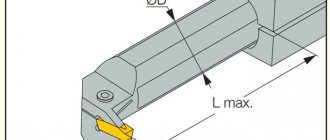
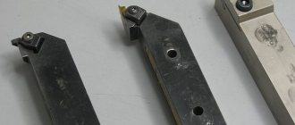
Mechanically fastened cutters for CNC machines
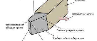
They are used for turning and boring on universal lathes, CNC lathes, OTs, and GPS lathes. Designed to perform various turning operations: external turning, turning of ends, recesses, chamfers, radius fillets, processing of through and blind holes.
The cutters are equipped with replaceable carbide cutting inserts and support plates. The plate fastening system is used according to ISO-M (clamp); P(vychag); S(screw); according to GOST 26613-85
Drill chuck GOST 2682-90
The chuck is used to secure the drill on the axis of the machine spindle; chucks are also used in hand drills. The advantage of the drill chuck is the ability to clamp the tool in a very wide range of diameters. The disadvantage is the high cost (the machines use precision drill chucks, which are much more expensive than those used in hand drills). Another disadvantage: the inability to absorb radial load, which makes it impossible to use it for milling. A drill chuck is used when it is necessary to clamp a small-diameter drill, most often solid carbide or high-speed steel.
Centering drills GOST 14952-90
In mechanical engineering, combined centering drills are used quite often for centering holes in workpieces and parts. The resulting centering holes are used for positioning in centers, for inserting drills and other technological operations. Centering drills are made mainly from high-speed steel grade R6M5. Centerings are manufactured in accordance with GOST 1495275 with specific dimensions. In the figure we see alignment without a safety cone of 60°, and in figure B there is a safety cone of 60° and 120°. When making alignments, instead of a cone, there may be a radius, as well as a twisted groove for chip exit. Some centering drills have a titanium oxide coating (yellow), which lowers the temperature in the cutting zone, but it is not recommended to work with such centering drills on titanium alloys (due to the centering coating, the centering process worsens). Combination center drills are manufactured with different D and d. The alignment is marked by d, for example: alignment d=1.6 means there will be a mark on the alignment, everything is standardized. Main dimensions of alignments: 1; 1.6; 2; 2.5; 3.15...6, as well as larger sizes.
Twist drills with tapered shank
GOST 10903-77
This standard applies to twist drills with a tapered shank with a diameter of 5 to 80 mm. The standard corresponds to the international standard ISO 235/1-1975, part concerning diameter dimensions.
Tool high-speed steel, analogue R6M5K5.
Adapter bushings GOST 13 598 - 85
The adapter sleeve is designed for quick tool changes with high centering accuracy and reliable fastening. There are many standards for various cones, differing in taper and design.
The tool with the foot is secured in the spindle by wedging this foot, for which there is a corresponding groove in the spindle sleeve. The foot is designed to make it easier to knock the cone out of the spindle and prevent rotation. Some cones are equipped with a system of holes and grooves for supplying cutting fluid (coolant).
Mandrel GOST 15067-90
A holder (mandrel) is an auxiliary tool for attaching cutters. There are several advantages to using toolholders. Instead of a solid cutter, in many cases, for ease of use, a holder with an adjustable cutter is used. As a rule, it is made of high-speed steel. An insert cutter can sharpen a part faster and better using a holder, since the cutter in the holder fits tightly to the working part and does the job just as efficiently. Another advantage of the holder is that for stripping, as well as heavy work, the holder together with the cutter can be rearranged in the tool holder of the caliper. With this installation, the cutting edge is behind the cutter body, which is the holder, thus, tool trembling or jamming is greatly reduced. The holder consists of three parts: Mandrel, Bracket, Screw
Three-jaw lathe chuck GOST 2675-80
The most common is the self-centering three-jaw chuck. The cams move simultaneously using a disk with an Archimedean spiral. The lower protrusions of the cams enter the turns of this spiral. On the reverse side of the disk there is a bevel wheel cut into a wheel, to which three bevel gears are connected. When you turn one of them with a key, the conical wheel of the disk also turns and, by means of a spiral, moves all three cams simultaneously and evenly along the grooves of the cartridge body; depending on rotation in one direction or another, the cams move closer or further from the center, respectively clamping or releasing the part. The cams are usually made in three stages and are hardened to increase wear resistance.
Measuring tool
Vernier caliper ShTs-1 166 -89
Vernier calipers are a universal tool designed for high-precision measurements of external and internal dimensions, as well as hole depths.
Vernier calipers are one of the most common measuring instruments due to their simple design, ease of use and speed of operation.
Plug gauge GOST 14810-80:
The plug gauge is used in serial and mass production to control holes. They are made double-sided (hollow) for holes up to 100mm and single-sided (incomplete) for holes over 100mm. If the pass-through plug PR passes into the hole without effort, and the non-go-through plug does not pass through, then the size of the hole is within the tolerance
⇐ Previous3Next ⇒
What will happen to the Earth if its axis shifts by 6666 km? What will happen to the Earth? - I asked myself...
WHAT IS CONFIDENT BEHAVIOR IN INTERPERSONAL RELATIONSHIPS? Historically, there are three main patterns of differences that exist between...
What does the IS operation and maintenance department do? Responsible for the safety of data (copying schedules, copying, etc.)…
WHAT AND HOW THEY WRITTEN ABOUT FASHION IN MAGAZINES AT THE BEGINNING OF THE XX CENTURY The first issue of the Apollo magazine for 1909 began, in fact, with a policy statement from the magazine’s editors...
Didn't find what you were looking for? Use Google search on the site: