APPENDIX 1 Recommended
CONSTRUCTION ELEMENTS AND GEOMETRICAL PARAMETERS OF COUNTERSINKERS
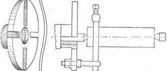
1. Structural elements and geometric parameters of countersinks with cylindrical and conical shanks are indicated in Figure 1 and Table 1, mounted ones - in Figure 2 and Table 2.
Type 1 and 3
Damn.1
Table 1
| 10 | 5 | 3 | 1,2 | 0,4 | 1,0 | 0,8 | 0,5 |
| 10,75 | |||||||
| 11 | |||||||
| 11,75 | 4 | ||||||
| 12 | 6 | 1,5 | |||||
| 12,75 | |||||||
| 13 | |||||||
| 13,75 | 7 | 5 | 2,0 | ||||
| 14 | |||||||
| 14,75 | |||||||
| 15 | |||||||
| 15,75 | 8 | 6 | 0,6 | 1,2 | 1,2 | 1,0 | |
| 16 | |||||||
| 16,75 | |||||||
| 17 | |||||||
| 17,75 | |||||||
| 18 | |||||||
| 18,70 | 9 | 7 | |||||
| 19 | |||||||
| 19,70 | |||||||
| 20 | |||||||
| 20,70 | 2,5 | ||||||
| 21 | |||||||
| 21,70 | 10 | 8 | |||||
| 22 | |||||||
| 22,70 | 3,0 | 0,7 | 1,5 | 1,5 | |||
| 23 | |||||||
| 23,70 | |||||||
| 24 | |||||||
| 24,70 | 11 | ||||||
| 25 | |||||||
| 25,70 | |||||||
| 26 | |||||||
| 27,70 | 12 | 9 | 1,5 | ||||
| 28 | |||||||
| 29,70 | |||||||
| 30 | |||||||
| 31,60 | 13 | 10 | |||||
| 32 | |||||||
| 33,60 | 14 | 3,5 | 0,8 | 1,8 | 1,8 | ||
| 34 | |||||||
| 34,60 | |||||||
| 35 | |||||||
| 35,60 | |||||||
| 36 | |||||||
| 37,60 | 15 | 11 | |||||
| 38 | |||||||
| 39,60 | |||||||
| 40 |
Type 2
Damn.2
table 2
mm
| 32 | 2,5 | 1,5 | 4 | 7 |
| 32,6 | ||||
| 33 | ||||
| 33,6 | ||||
| 34 | ||||
| 34,6 | ||||
| 35 | ||||
| 35,6 | ||||
| 36 | ||||
| 36,6 | ||||
| 37 | ||||
| 37,6 | 8 | |||
| 38 | ||||
| 38,6 | 5 | 9 | ||
| 39 | ||||
| 39,6 | ||||
| 40 | ||||
| 41,6 | 3,0 | |||
| 42 | ||||
| 43,6 | 10 | |||
| 44 | ||||
| 44,6 | ||||
| 45 | ||||
| 45,6 | ||||
| 46 | ||||
| 46,6 | ||||
| 47 | ||||
| 47,6 | 3,5 | 6 | 11 | |
| 48 | ||||
| 49,6 | 2,0 | |||
| 50 |
2. The main dimensions of countersinks with intermediate diameters with a conical shank are indicated in Table 2a, mounted ones - in Table 2b, with a cylindrical shank - in Table 2c.
Table 2a
mm
| Morse cone | |||
| St. 7.80 to 8.50 | 156 | 75 | 1 |
| » 8,50 » 9,50 | 162 | 81 | |
| » 9,50 » 10,60 | 168 | 87 | |
| » 10,60 » 11,80 | 175 | 94 | |
| » 11,80 » 13,20 | 182 | 101 | |
| » 13,20 » 14,00 | 189 | 108 | |
| » 14,00 » 15,00 | 212 | 114 | 2 |
| » 15,00 » 16,00 | 218 | 120 | |
| » 16,00 » 17,00 | 223 | 125 | |
| » 17,00 » 18,00 | 228 | 130 | |
| » 18,00 » 19,00 | 233 | 135 | |
| » 19,00 » 20,00 | 238 | 140 | |
| » 20,00 » 21,20 | 243 | 145 | |
| » 21,20 » 22,40 | 248 | 150 | |
| » 22,40 » 23,02 | 253 | 155 | |
| » 23,02 » 23,60 | 276 | 155 | 3 |
| » 23,60 » 25,00 | 281 | 160 | |
| » 25,00 » 26,50 | 286 | 165 | |
| » 26,50 » 28,00 | 291 | 170 | |
| » 28,00 » 30,00 | 296 | 175 | |
| » 30,00 » 31,50 | 301 | 180 | |
| » 31,50 » 31,75 | 306 | 185 | |
| » 31,75 » 33,50 | 334 | 4 | |
| » 33,50 » 35,50 | 339 | 190 | |
| » 35,50 » 37,50 | 344 | 195 | |
| » 37,50 » 40,00 | 349 | 200 | |
| » 40,00 » 42,50 | 354 | 205 | |
| » 42,50 » 45,00 | 359 | 210 | |
| » 45,00 » 47,50 | 364 | 215 | |
| » 47,50 » 50,00 | 369 | 220 |
Note. The lengths and can vary within one diameter interval between the minimum and maximum values corresponding to those given in the table for the nearest lower and upper limits of the interval.
For example, for a diameter of 15 mm, the length can vary between 108 and 120 mm with a nominal value of 114 mm, with a tolerance of ±6 mm.
Since the length tolerance is the same as the length (±6 mm), the length can vary between 206 and 218 mm with a nominal value of 212 mm.
Table 2b
mm
| St. 23.6 to 35.5 | 1З | 45 |
| » 35,5 » 45,0 | 16 | 50 |
| » 45,0 » 53,0 | 19 | 56 |
| » 53,0 » 63,0 | 13 | 45 |
| » 63,0 » 75,0 | 27 | 71 |
| » 75,0 » 90,0 | 32 | 80 |
| » 90,0 » 101,6 | 40 | 90 |
Note. Countersink dimensions comply with ISO 3314-75.
Table 2c
mm
| Up to 3.00 | 61 | 33 |
| St. 3.00 to 3.35 | 65 | 36 |
| » 3,35 » 3,75 | 70 | 39 |
| » 3,75 » 4,25 | 75 | 43 |
| » 4,25 » 4,75 | 80 | 47 |
| » 4,75 » 5,30 | 86 | 52 |
| » 5,30 » 6,00 | 93 | 57 |
| » 6,00 » 6,70 | 101 | 63 |
| » 6,70 » 7,50 | 109 | 69 |
| » 7,50 » 8,50 | 117 | 75 |
| ” 8,50 » 9,50 | 125 | 81 |
| » 9,50 » 10,60 | 133 | 87 |
| » 10,60 » 11,80 | 142 | 94 |
| » 11,80 » 13,20 | 151 | 101 |
| » 13,20 » 14,00 | 160 | 108 |
| » 14,00 » 15,00 | 169 | 114 |
| » 15,00 » 16,00 | 178 | 120 |
| » 16,00 » 17,00 | 184 | 125 |
| » 17,00 » 18,00 | 191 | 130 |
| » 18,00 » 19,00 | 198 | 135 |
| » 19,00 » 20,00 | 205 | 140 |
Note. The lengths and can vary within one diameter interval between the minimum and maximum values corresponding to those given in the table for the nearest lower and upper limits of the interval.
For example, for a diameter of 4 mm, the length can vary from 39 to 47 mm with a nominal value of 43 mm and the length can vary from 70 to 80 mm with a nominal value of 75 mm.
(Introduced additionally, Amendment No. 3).
Section 1. (Changed edition, Amendment No. 4).
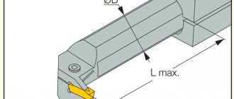
DIMENSIONS OF CUTTER PROFILE FOR MACHINING HELICAL GROOVES AND BACKS OF COUNTERSINK TEETH
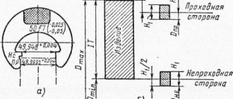
2.1. Dimensions of the profile of cutters for processing helical grooves and backs of three-tooth countersinks in Figures 3 and 4 in Tables 3, 4, four-tooth countersinks - in Figure 5 and Table 5.
Damn.3
Table 3
mm
| For countersinks with diameter | ||||||||
| St. 10 to 11 | 5,10 | 2,31 | — | 3,00 | 0,25 | 1,00 | 5,10 | 3,80 |
| » 11 » 12 | 6,75 | 3,17 | 0,14 | 3,84 | — | 1,60 | 6,75 | 5,48 |
| » 12 » 14 | 6,90 | 3,23 | 4,20 | 7,45 | 1,44 | 2,00 | 6,90 | 8,50 |
| » 14 » 15 | 7,85 | 3,78 | 3,65 | 7,50 | 1,46 | 2,25 | 7,85 | 8,65 |
| » 15 » 16 | 9,00 | 3,60 | 2,65 | 7,10 | 1,25 | 2,00 | 9,00 | 8,05 |
| » 16 » 17 | 8,20 | 4,46 | 4,75 | 9,25 | 2,23 | 2,35 | 8,20 | 10,20 |
| » 17 » 18 | 8,20 | 3,98 | 4,80 | 8,70 | 1,48 | 2,45 | 8,20 | 10,10 |
| » 18 » 19 | 9,30 | 4,86 | 5,85 | 10,60 | 3,82 | 2,8 | 9,30 | 10,10 |
| » 19 » 21 | 8,25 | 4,51 | 5,55 | 10,05 | 2,33 | 2,40 | 8,25 | 10,40 |
| » 21 » 23 | 9,65 | 4,97 | 6,80 | 11,80 | 3,13 | 2,80 | 9,65 | 11,95 |
| » 23 » 25 | 12,65 | 5,33 | 8,40 | 13,00 | 3,70 | 4,00 | 12,65 | 13,65 |
| » 25 » 27 | 15,70 | 5,88 | 4,40 | 12,45 | 0,70 | 3,00 | 15,70 | 15,05 |
| » 27 » 30 | 14,00 | 6,92 | 7,50 | 15,05 | 3,09 | 3,65 | 14,00 | 16,35 |
| » 30 » 36 | 17,00 | 7,92 | 0,31 | 9,61 | — | 4,00 | 17,00 | 13,67 |
| » 36 » 40 | 18,87 | 8,79 | 0,34 | 10,65 | — | 4,44 | 18,87 | 15,17 |
2.2. It is permitted to manufacture countersinks with a chip flute profile different from the specified shape.
Damn.4
Table 4
Dimensions in mm
| For countersinks with diameter | (prev. shutdown by ) | |||
| 10-11 | 10,6 | 7,4 | 5,0 | 20° |
| 11,5-12 | 11,2 | 8,0 | 5,5 | |
| 13 | 11,6 | 8,4 | 6,0 | |
| 14 | 12,2 | 9,0 | 6,5 | |
| 15 | 12,6 | 9,4 | 7,0 | |
| 16 | 14,0 | 10,8 | 7,5 | |
| 17 | 14,6 | 11,4 | 8,0 | |
| 18 | 15,2 | 12,0 | 8,5 | |
| 19 | 15,8 | 12,5 | 9,0 | |
| 20 | 16,4 | 13,2 | 9,5 | |
| 21 | 17,0 | 13,8 | 10,0 | |
| 22 | 17,6 | 14,4 | 10,5 | |
| 24 | 19,0 | 15,8 | 11,5 | |
| 25 | 20,0 | 16,5 | 12,0 | |
| 26 | 20,7 | 17,2 | 12,5 | |
| 27 | 21,4 | 17,9 | 13,0 | |
| 28 | 22,2 | 18,7 | 13,5 | |
| 30 | 23,6 | 20,1 | 14,5 | |
| 32 | 24,8 | 21,5 | 15,5 | 25° |
| 34 | 26,5 | 23,0 | 16,5 | |
| 35 | 27,2 | 23,7 | 17,0 | |
| 36 | 27,9 | 24,4 | 17,5 | |
| 37 | 28,7 | 25,2 | 18,0 | |
| 38 | 29,4 | 25,9 | 18,5 | |
| 40 | 39,5 | 29,5 | 19,5 |
Damn.5
Table 5
mm
| For countersinks of size | cutters | |||||
| St. 30 to 38 | 63 | 4,0 | 32 | 0,20 | 15,4 | 20,0 |
| » 38 » 46 | 5,0 | 38 | 0,25 | 18,6 | 24,1 | |
| » 46 » 60 | 80 | 6,0 | 45 | 24,3 | 31,5 | |
| » 60 » 70 | 7,0 | 54 | 0,30 | 28,3 | 36,8 | |
| » 70 » 80 | 100 | 8,0 | 58 | 0,40 | 32,4 | 42,0 |
3. INSTALLATION OF GROOVE MILLS WHEN MILLING HELICAL GROOTS OF COUNTERSKINS
3.1. The installation diagram for groove cutters when milling helical grooves of countersinks is shown in Figure 6 and Table 6.
Damn.6
Table 6
Dimensions in mm
| Countersink diameter | Number of grooves | Cutter diameter | Installation size | ||
| From 10 to 11.5 | 3 | 63 | 34,0 | 20° | -0,02 |
| 12 | 34,5 | -0,02 | |||
| 13 | 80 | 43,0 | -0,03 | ||
| 14 | 43,5 | ||||
| 15 | |||||
| 16 | 44,0 | 0,00 | |||
| 17 | -0,11 | ||||
| 18 | -0,2…..* | ||||
| 19 | 44,5 | -0,21 | |||
| From 20 to 21 | -0,21 | ||||
| 22 | 45,0 | -0,07 | |||
| 24 | 100 | 55,0 | -0,33 | ||
| 25 | 55,5 | ||||
| From 26 to 27 | -0,18 | ||||
| » 28 » 30 | 125 | 68,5 | -0,22 | ||
| 32 | 69,0 | -0,12 | |||
| From 34 to 36 | 69,5 | 0,00 | |||
| » 37 » 40 | 70,0 | 0,00 | |||
| 33 | 4 | 63 | 39,3 | 15° | 10,65 |
| 34 | 40,1 | 11,10 | |||
| 35 | 40,6 | 11,50 | |||
| 36 | 41,60 | 11,60 | |||
| 37 | 41,50 | 11,74 | |||
| 38 | 41,90 | 11,89 | |||
| 40 | 41,40 | 12,90 | |||
| 42 | 42,20 | 13,60 | |||
| 45 | 43,60 | 14,50 | |||
| 48 | 80 | 50,95 | 16,20 | ||
| 50 | 52,75 | 16,65 | |||
| 52 | 52,75 | 17,55 | |||
| 55 | 54,10 | 17,85 | |||
| 58 | 55,60 | 18,15 | |||
| 60 | 56,65 | 18,75 | |||
| 62 | 55,20 | 20,60 | |||
| 63 | 56,10 | 20,50 | |||
| 65 | 57,00 | 20,80 | |||
| 68 | 58,20 | 21,40 | |||
| 70 | 59,40 | 22,20 | |||
| 72 | 100 | 68,20 | 23,60 | ||
| 75 | 69,60 | 23,60 | |||
| 78 | 71,40 | 24,80 | |||
| 80 | 71,40 | 25,40 | |||
________________
* Defect of the original. — Note "CODE".
Section 2, 3. (Changed edition, Amendment No. 3).
The countersink is also selected depending on the task of processing the part.
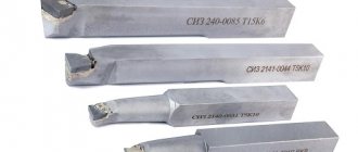
- Conical. Parts for processing conical surfaces on steel workpieces (for various sensors, valves, etc.) and for working with other types of steel materials.
— End ones. They are used to ensure that the end planes of the part are protected.
- Cylindrical. Parts are manufactured according to special GOST standards. Countersinks of this type are intended for processing surfaces of various cylindrical types and shapes. They differ from each other in angle of inclination, diameter, and coating, which can be made of different surfaces, but they have one thing in common - they are made of wear-resistant material.
Some requirements that this tool must meet
The selected countersink (according to GOST or reference books, or both) must comply with the following technical conditions of use:
— In products made of structural steel, holes with a diameter of up to 8 centimeters are bored using high-speed steel equipment. Its diameter should reach 32-80 mm. The equipment must have attachment heads.
— If the product is made of non-ferrous metals or cast iron, a feather tool is used to bore blind holes.
— If the product was made of hardened steel, which was difficult to process, you need to use a tool with carbide plates to stretch the holes in this part, their diameter is about 14 mm-5 cm. And the tool should have 3-4 teeth.
Purpose of countersinking and equipment used
Countersinking allows you to improve the quality of the surface obtained during drilling to 9-11 quality accuracy and roughness Rz 2.5 microns. At the same time, all defects arising during casting, stamping and drilling of holes are eliminated, surface cleanliness and accuracy are increased, and alignment is increased. The advantage of a countersink over a conventional drill is its higher rigidity due to the cutting teeth, which ensures high precision in the direction of movement of the tool.
The main purpose of the countersink:
- Improves accuracy and surface finish of holes before tapping or reaming.
- Sizing pre-drilled holes for studs, bolts and other types of fasteners.
Countersinking is a machine operation and is performed on:
- drilling machines of all types;
- lathes;
- boring machines;
- aggregate machines, as an operation in an automatic line;
- horizontal and vertical milling machines.
Areas of application for countersinks
Countersinking and countersinking, despite the fact that they are used for processing pre-prepared holes, have a number of fundamental differences. The main purpose of countersinking is to form conical or cylindrical recesses in the upper part of a pre-prepared hole, which are necessary to hide the heads of the fasteners used.
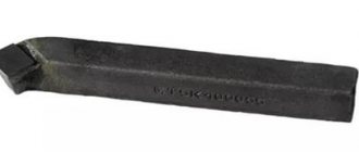
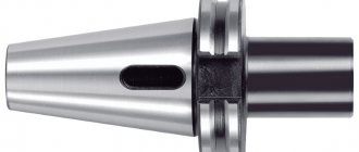
Conical countersink with Morse shank type 8, cutting part material - HSS steel (analogous to P6M5)
Based on the degree of cleanliness of the recess formed during the countersinking process, such a technological operation is classified as semi-finishing. As a rule, it is performed before drilling holes in workpieces made of various materials. The equipment used for countersinking can be drilling, turning, milling and boring machines. A distinctive feature of this technological operation is that it is performed at low speeds, performed by a countersink or the workpiece being processed.
According to their design, countersinks are distinguished:
- conical (GOST 14953-80);
- cylindrical type.
Types of Conical Countersinks
A separate category of countersinks consists of cutters, which are made of carbide materials and are used primarily for grinding and roughing work. Another type of countersinks that are used for machining and chamfering holes located in hard-to-reach places are reverse-type tools. Specialists who often work with countersinks of this type prefer to have at their disposal entire sets of them, which allow them to process holes with various geometric parameters.
Roller cutter is a type of countersink used for cutting valves of an internal combustion engine
Conical countersinks produced in accordance with GOST 14953-80 have a standard design, the constituent elements of which are a shank and a working part with a front end sharpened to a cone. The cone angle, which is formed by the side surfaces of the front part of such a countersink, can be 60, 75, 90 or 120°. GOST 14953-80 also regulates the number of teeth on the working part, which depends on its diameter.
Thus, countersinks of various diameters (12–60 mm) may contain from six to twelve cutting teeth. Depending on the length of the tool used for processing, which is also regulated by the provisions of the regulatory document, a trunnion can be used to support it on the machine, ensuring the alignment of the surface being formed.
Types of Standard Conical Countersinks
Cylindrical countersinks, in contrast to conical tools (manufactured according to the requirements specified by GOST 14953-80), are specifically used for cutting chamfers for metal products. The working part of such a countersink, which usually has a wear-resistant coating, resembles a drill, but differs from it in a large number of cutting teeth. Depending on the diameter of the working part, it can have from 4 to 10 cutting teeth. To reliably fix the position of such a tool during its operation, there is a special guide pin at its end - solid or removable. The most convenient and practical to use are countersinks with removable trunnions. In addition, for greater efficiency of the processing performed, an additional cutting attachment can be installed on the countersink.
In order to process several holes to the same depth using one countersink, the tool is equipped with a special holder with a limiter, which can be stationary or rotating. In this case, the cutting tool is mounted in a holder, and its working part protrudes from its stop by an amount equal to the depth of the hole being machined.
These chamfers on the holes were made with a conical countersink
Various metals and alloys can be used as materials for the manufacture of countersinks, in particular:
- carbon tool steels;
- alloyed high-speed steel alloys;
- carbide materials.
For processing holes made in soft metals, as well as in materials such as wood or plastic, countersinks made of steel alloys are used. If it is necessary to process holes made in products made of harder metals, then carbide countersinks are used for this. The latter are able to withstand significant loads arising when processing metals with high hardness.
How are countersinks divided according to this parameter?
— When processing cast iron holes and high-alloy steels, an angle of 0-5 degrees is used.
— When processing materials with a medium degree of hardness, an angle of 8-10 degrees is used.
— For processing light types of steel, an angle of 15-20 degrees is used.
In other words, if you use a countersink, you can achieve a lot. For example, significantly expand the diameter of the product. For example, the level of entry becomes more accurate, the surface of the holes, it is possible to create additional holes for various types of fasteners. These include, for example, bolts, etc.