Types of calibers and their scope
TO
category:
Turning
Types of calibers and their scope
Next: Technological process for making smooth gauges
In mechanical engineering, the so-called alternative method of monitoring product shelf life is widely used. It allows you to divide products into good and defective. In this case, the actual values of the parameter being checked are not determined, but the fact of its compliance with the standard is established. When alternatively checking the geometric parameters of products, gauges are most often used.
Calibers are scaleless measuring instruments for checking linear dimensions, angles, shapes and relative positions of surfaces. There are several types of calibers.
Rice. 1. Smooth clamp gauge (a) and its tolerance range (b)
Smooth clamp gauges (Fig. 1) are used to control the lengths and diameters of the outer surfaces. They can be one-sided and two-sided, one-limit and two-limit. Single-determined staple gauges are made either passable or non-passable. To control the dimensions of the 8th accuracy class (and less accurate), clamp gauges with replaceable jaws are used. To control more precise products (up to 6th quality), the working surfaces of the gauges are equipped with a hard alloy. In small-scale and individual production, clamp gauges are made from sheets, in large-scale and mass production - from forgings and castings.
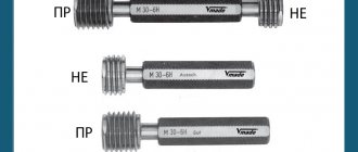
Smooth plug gauges (Fig. 2) are used to control holes. Structurally, they are made in the form of a handle and a working part. The working part can be made integral with the handle or in the form of inserts and attachments. For plug gauges designed to control precise holes (6-12 grades), the inserts are made of hard alloy. Plug gauges can be single-sided or double-sided. One-sided ones are made passable or non-passable.
Smooth gauges allow you to control linear dimensions from 0.1 to 3150 mm. As the dimensions increase, the control error increases due to the increase in elastic deformations of the gauges.
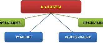
For smooth plug gauges, the through side (PR) has the smallest limit size (i.e., it must pass into the hole), and the non-go through (NOT) side has the largest limit size (i.e., it must not pass into the hole). For smooth staple gauges, the through side (PR) has the largest maximum size, and the non-through side (NOT) has the smallest. According to their purpose, gauges are divided into working gauges (P), intended for checking parts by workers and quality control inspectors, receiving gauges (P), for checking parts by representatives of the customer, control gauges (K), for checking working and receiving gauges during the process of their manufacture and operation, and counter gauges ( K—I)—to control the wear of working calibers.
Rice. 2. Smooth plug gauge (a) and its tolerance range (b)
Rice. 3. Types of gauges: 1 - measuring plane, 2 - guide plane, 3 - product, 4 - marks
The gauges are marked with their type, the pass and fail sides, the controlled nominal size, the designation of the checked tolerance range, and the manufacturer's trademark.
Calibers for controlling dimensions in height and depth are varied both in design and principle of operation. The most commonly used calibers are those using the “light slit” method. The extreme sides of these calibers are designated by the letters B (large) and M (smaller).
Cone gauges are designed for testing smooth conical surfaces. Most often they control the conical shanks of tools (bushing gauges) and conical holes for their fastening (plug gauges). The limiting positions of the gauges relative to the controlled surface are determined by two marks marked on the gauge. Typically, such gauges are used in a set consisting of a plug gauge, a bushing gauge and a counter-plug gauge. The latter is designed to allow the bushing gauge to be fitted to the paint plug gauge.
Gauges for checking the shape and relative position of surfaces have a wide variety of designs. They can control the parallelism of planes, the alignment of holes, the symmetry of grooves, the parallelism of the plane and the axis of the hole, spline shafts and bushings, etc.
Thread gauges are used for comprehensive thread control. The external thread is controlled with a ring gauge, and the internal thread with a plug gauge. Thread gauges are manufactured and used in sets, which, in addition to the thread gauge, include control pass and no-go gauges. Along with unregulated calibers, adjustable ones are also used. The latter are adjusted using installation thread gauges, which in this case are also included in the kit.
Profile templates are flat gauges used to control the profile of shaped surfaces of a product. Control with such a template is carried out using the “light slit” method. The manufacturing accuracy of the profile template itself and its wear are checked using counter templates. The gauges are made from structural, tool and tool alloy steels. Equipping the working part of the caliber with hard alloy VK8 increases its durability several tens of times compared to calibers made of carbon tool steel.
Tool design
This measuring tool is made from a solid metal bar. At both ends there are cylindrical elements of a given diameter. Therefore, they are divided into the following classes:
- measuring;
- threaded;
- smooth (one-sided or two-sided);
- checkpoints;
- limit.
Each device structurally consists of the following elements:
- handles (with applied corrugation according to GOST 14748-69);
- inserts;
- dowels;
- fixing screw.
Download GOST 14748-69
For example, a threaded plug gauge as an insert is used to check metric threads. They are divided into two categories: for checking threads from 1 to 68 mm and from 68 to 200 mm. Requirements for them are given in special standards. All screw plugs are available in full or short thread designs. Each of the plugs has its own specific application.
Based on established standards, smooth limit plugs are divided into the following designs:
- double-sided with cylindrical inserts;
- with conical inserts;
- with cylindrical nozzles;
- complete and incomplete;
- single-sided sheets;
- full and incomplete washers.
The smooth double-sided plug gauge has corresponding inserts at both ends of the handle. One plug is called a through plug and is designated by the abbreviation “PR”. The second plug is not passable and is marked “NOT”. The dimensions of smooth plug gauges are determined by their purpose and are given in the standard for such instruments. The main parameters are the outer diameter, the size of the head (insert) and the processing accuracy class. To carry out inspections of holes with a diameter ranging from five to twenty millimeters, a cone-shaped nozzle is made for the plug. For holes of larger diameter, such a nozzle is made cylindrical.
Smooth straight-through plugs are produced based on existing standard sizes. Intermediate plugs have the closest size according to GOST. Limit plug gauges consist of the same elements as pass-through gauges. Each size of an individual plug part is indicated on the drawing. It serves to determine the exact size of the structure and the order of its application.
Purpose of the plug gauge
These scaleless measuring systems are used to check the accuracy of machining operations performed on various parts. Depending on the type of work (turning, milling, drilling), plugs are designed to control the following results:
- diameter of the drilled hole after all types of processing;
- establishing the accuracy class of surface treatment;
- geometric (linear) dimensions;
- angles of inclination of surfaces relative to given normals;
- compliance of the shape of the processed part with the specified parameters;
- correct relative position of surfaces;
- correct thread cutting (internal and external).
The absence of a direct indicator, scale or digital, in these measuring instruments requires the creation of a large number of such devices. This is due to the fact that each tool can only be used to monitor one parameter. The use of such measuring devices makes it possible to mechanize the inspection operation and reduce the time in the technological chain for this operation. Reducing the time required to monitor mandatory parameters can significantly increase labor productivity.
Therefore, the following types of products are currently used:
- smooth plug gauges;
- staples;
- feelers (usually flat plates of a certain thickness for measuring the gap between parts, that is, checking its permitted value);
- conical (the nozzle has the shape of a cone at a given angle of inclination);
- for the relative position of surfaces;
- thread gauges (for checking cylindrical threads of various sizes).
Each of the listed types has its own purpose. The first type is intended for assessing the parameters of manufactured pipes. It is used to quickly check the quality of manufactured pipelines. Compliance with all necessary parameters established by the standard.
Threaded ones are intended only for checking the quality of the cut thread. They are made shortened or full (to increase control accuracy). With the help of shortened gauges, only part of the cut thread can be checked, which makes it difficult to obtain a complete picture of the quality of the manufactured part. To get a complete picture of accuracy and quality, threads are tested using full thread designs.
Full control of pipe products is carried out using threaded and smooth gauges.
Calibers. Caliber control. Types, device, designation of calibers.
Rice. 2.44. Gauge-staples
Preference is given to one-sided limit calibers. They reduce product inspection time and material consumption.
Gauge clamps for shaft inspection.
Limit and adjustable clamp gauges are used (GOST 18358-93 - GOST 18369-93). Limit gauge staples include: single-sided sheet staples (Fig. 2.44, a) and double-sided; stamped staples are single-sided (Fig. 2.44, b), double-sided (Fig. 2.44, c) and single-sided with a handle (Fig. 2.44, d).
Adjustable calipers (Fig. 2.45) allow you to compensate for wear and can be adjusted to different sizes related to certain intervals. However, compared to non-adjustable staples, they have less accuracy and reliability and are usually used for dimensional control with tolerances no more precise than 8th grade accuracy.
Rice. 2.45. Adjustable clamp gauge
According to their purpose, limit gauges are divided into working, receiving and control.
Working gauges are designed to control parts during their manufacturing process. They are used by equipment operators and adjusters, as well as quality control inspectors of the manufacturing plant.
Receiving gauges are used for acceptance of parts by customer representatives.
To install adjustable calipers and control non-adjustable gauges, as well as to remove them from service due to wear, control gauges (K-I), which have the shape of washers, are used (see Fig. 2.43, h). Despite the small tolerance of control gauges, they still distort the established tolerance fields for the manufacture and wear of working gauges, so instead of them, if possible, it is advisable to use gauge blocks or universal measuring instruments.
Inserts and nozzles of plug gauges are made of steel X in accordance with GOST 5950 - 2000 or ShKh-15 in accordance with GOST 801-78. It is allowed to manufacture inserts and nozzles from steel U10A or U12A for all types of calibers, except for incomplete gauge plugs obtained by stamping, as well as from steel 15 or 20 for calibers with a diameter of more than 10 mm.
When manufacturing caliber parts with a working surface made of carburized steel 15 or 20, the thickness of the carburization layer must be at least 0.5 mm. The working surfaces, as well as the surfaces of the lead-in and exit chamfers (blunts) of all types of plug gauges measuring 1...100 mm (except for sheet and partial gauge plugs) are chrome plated or other wear-resistant coating is applied.
Hardness of working surfaces and surfaces of lead-in and exit chamfers of gauge plugs with chrome coating - HRC3
57...65. The roughness parameters of the working surfaces must be within the range of Ra 0.04...0.32 microns, depending on the type of gauge, the accuracy of the controlled parameter of the product and its size.
To increase wear resistance and reduce costs in production conditions, gauges with inserts and nozzles made of carbide materials are often used (GOST 16775 - 93 - GOST 16780 - 71). The wear resistance of such calibers is 50...150 times higher compared to the wear resistance of chrome-plated calibers, while the cost of the calibers increases by 3...5 times.
Rice. 2.46. Sketches of a plug gauge (a), a clamp gauge (b) and a washer gauge (c)
Technical requirements for smooth unregulated calibers are established by GOST 2015 - 84.
The caliber marking provides the nominal size of the part for which the caliber is intended, the letter designation of the product tolerance field, numerical values of the maximum deviations of the product in millimeters (on working calibers), the type of caliber (for example, PR, NE, K-I) and the trademark of the manufacturing plant - la. In Fig. 2.46 shows sketches of a plug gauge (GOST 14810 - 69), a clamp gauge (GOST 18360 - 93) and a control washer gauge, indicating standard markings, executive dimensions, shape accuracy and roughness of working surfaces.
Calibers for monitoring the depths and heights of ledges.
These calibers (Fig. 2.47) form a special group. Structurally, they are stepped plates of one shape or another. GOST 2534 - 77 provides for types of gauges covering sizes
1…500 mm 11…18 accuracy grades. Calibers determine the suitability of a product by the presence of a gap between the corresponding planes of the caliber and the product. Instead of pass and fail sides, these gauges have sides corresponding to the largest (B) and smallest (M) maximum dimensions of the product.
The main methods of control are the following methods: light slit, or through the light, pushing, touch, by risks.
The means of control also depend on the chosen method:
— calibers for control of transmission (Fig. 2.47, a, b, c);
— gauges for control by the sliding method (see Fig. 2.47, d, e, f);
— gauges for control by touch (Fig. 2.47, g, h);
— calibers for risk control (Fig. 2.47, i, j).
Calibers using the transmission method control tolerances of at least 0.04...0.06 mm. The minimum tolerances of products controlled by step-rod gauges are 0.03 mm, and those controlled by touch - 0.01 mm.
Rice. 2.47. Calibers for monitoring the depths and heights of ledges
Rice. 2.48. Types of cone gauges
In the ISO system, the limiting gauges for depths and heights are not standardized.
Cone gauges.
The control of the outer cones is carried out with cone gauge bushings, and the control of the internal cones is carried out with cone gauge plugs. GOST 24932 - 81 establishes types and designs of gauges for smooth cones with separate standardization of each type of tolerance with diameters in a given section up to 200 mm, taper from 1:3 to 1:50, diameter tolerances 6... 12 qualifications, cone angle tolerances 4...9 degrees of accuracy. Some representatives of cone gauges are shown in Fig. 2.48.
Notation examples:
caliber bushings 40 of the 4th and 5th degree of accuracy - “Bushing 40 AT4, GOST 20305 - 94”;
control plug gauge 60 of the 6th and 7th degree of accuracy - “Plug 60-K AT6, GOST 20305 - 94”.
Gauges for surface position control.
Tolerances, methods for calculating executive dimensions and general instructions for the use of gauges to control the location of surfaces are established by GOST 16085 - 80.
It applies to gauges of a one-piece design designed to control surfaces (their axes or planes of symmetry) with dependent location tolerances, as well as to control the straightness of an axis with a dependent shape tolerance.
The measuring surfaces of location gauges are a composition of elements that reproduce the totality of surfaces of mating parts.
In this case, the dimensions of individual measuring surfaces are made according to the most unfavorable size for assembly (according to the passage limit), and their relative position or location relative to the base element is maintained with very high accuracy according to the nominal dimensions indicated on the product drawing.
Accuracy control gauges for cylindrical threads.
With the help of gauges, complex and differentiated (element-by-element) methods are used. The complex method is used for threaded parts whose average diameter tolerance is total. It is based on the simultaneous control of the average diameter (d2 (D2)), pitch (P), half of the profile angle (a/2), as well as the internal (d, (D,)) and external (d (D)) diameters of the thread by comparison of the actual contour of a threaded part with the limit ones.
With a differentiated control method, the internal and external diameters d, pitch P and half the profile angle a/2 are checked separately using conventional smooth gauges and templates.
All types of gauges and counter gauges (37 types in total) for cylindrical threads (metric, trapezoidal, pipe and thrust) are established by GOST 24939 - 81. The design dimensions of thread gauges and their elements are regulated by GOST 18465-73 and GOST 18466 - 73.
The set of thread gauges includes working smooth and threaded go and no-go gauges, gauges and counter gauges (KPR, PR, KPR-NE, KNE-PR, KNE-NE, KI-NE, U-NE, U-PR) for checking and adjustment (installation) of working threaded brackets and rings.
Symbol (type number) of some calibers according to GOST 24997-81:
PR (1) - non-adjustable threaded ring gauge;
KPR-PR (2) - threaded control plug gauge for a new threaded straight-through non-adjustable ring gauge;
KNE-NE (3) - threaded control plug gauge, non-go through, for a new threaded straight through, non-adjustable, non-go through gauge ring;
PR (4) - adjustable threaded ring gauge;
PR (7)—threaded pass-through clamp gauge;
U-PR (8) - threaded installation plug gauge for threaded pass-through clamp gauge.
Go-through thread gauges must be screwed with the thread being tested. The screwability of the gauge with the nut means that the given average and outer diameters of the nut thread do not exceed the established minimum dimensions.
The marking of a thread gauge involves the application of a thread designation, a thread tolerance field, the purpose of the gauge (for example, PR), a trademark of the manufacturer, and on gauges with left-hand threads the letters “Ш” are added.
On calibers used for the manufacturer's own needs, the trademark may not be applied.
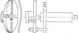
The nominal thread pitch (or number of threads per inch) is determined using thread templates (thread gauges) (Fig. 2.49, a). In accordance with TU 2-034-228 - 87, thread templates are produced in sets for metric threads with pitches from 0.4 to 6 mm inclusive (20 templates) and for inch threads with the number of threads per inch from 28 to 4 inclusive (17 templates) .
When applying a template to a thread profile (Fig. 2.49, b), it should be as long as possible, as this increases the accuracy of determining the pitch.
Complex feedthrough gauges.
The accuracy of the dimensions, shape and position of the surfaces of parts with straight-sided splines is, as a rule, controlled by complex pass-through gauges (GOST 24959-81, GOST 24960-81): spline bushings are checked by gauge plugs, and spline shafts are checked by gauge rings.
Rice. 2.49. Thread templates (thread gauges): a - set; b - control principle
Rice. 2.50. Probe gauges (a) and control using probes (b, c]
If necessary, element-by-element control of centering and non-centering diameters, width of depressions and splines is also carried out using special smooth gauges in accordance with GOST 24961-81 - GOST 24968-81.
The symbol of the caliber consists of the name of the caliber (“plug” or “ring”), the number of the type of caliber, the symbol of the splined shaft sleeve for which the caliber is intended, the degree of accuracy of the caliber and the designation of the standard.
Notation examples:
ring gauge of the 1st type, 4th degree of accuracy for a shaft 50x2x9d according to GOST 6033 - 80 - “Ring 1-50x2x9g / 4, GOST 24969 - 81”;
complex gauge-plug of the 5th type of the 4th degree of accuracy for the splined bushing 50x2x9N in accordance with GOST 6033 - 80 - "Plug 5-50x 2 x 9N/4 GOST 24969-81".
Probe gauges.
These are normal gauges for checking the gap between surfaces (Fig. 2.50). Probes are plates with parallel measuring planes. In accordance with TU 2-034-0221197 - 91, probes are manufactured in lengths of 100 and 200 mm. Styli with a length of 100 mm can be manufactured individual plates and sets (of four numbers), including the following nominal plate sizes:
set No. 1 (9 probes) - with a thickness from 0.02 to 0.1 mm with gradation every 0.01 mm;
set No. 2 (17 probes) - with a thickness from 0.02 to 0.5 mm;
set No. 3 (10 probes) - with a thickness from 0.055 to 1 mm with gradation every 0.05 mm;
set No. 4 (10 probes) - with a thickness from 0.1 to 1 mm with gradation every 0.1 mm.
When using feeler gauges, either one of them is used, or two or more feeler gauges are added together to achieve the required thickness.
The permissible deviations in the thickness of new styli range from 5 to 15 microns, depending on their nominal thickness. When using a set of probes, the control error increases.
How to use the tool
The rules for using such tools depend on their purpose. It is allowed to be used only in compliance with certain rules and the established accuracy class indicated in the marking. The use of plug gauges to control the accuracy of manufactured holes is allowed only with the help of a tool close to the parameters of the hole itself. The main condition for measurement accuracy is the free passage of the gauge insert through the hole being measured. Correct use of such devices requires compliance with the following rules:
- the passage side should enter the hole only under the influence of its own weight;
- It is prohibited to use additional methods of external influence (additional pressure, blows);
- Before checking, it is necessary to clean the parts from dirt and mechanical processing residues;
- Any type of lubricant that could affect the penetration of the gauge into the hole should be removed;
- the check must be carried out without rotating the meter relative to the part being examined;
- a prerequisite is compliance with the temperature regime (parts should be checked only at natural temperature);
- The frequency of inspections of the instrument itself and the rules for recording the results in established documents must be observed;
- each caliber must be stored in accordance with the established storage procedure (they should not come into contact with other metal parts or be exposed to external influences).
The thread template should be used in compliance with the characteristics of the thread (external or internal).
To control external threads, it is enough to apply the tool itself to the threads and determine the degree of coincidence. The internal thread is checked by screwing the head into a finished threaded hole. The process should be easy without effort or distortion.
To check the surface of the tapered shaft, use a suitable smooth tool. Quality is determined by the alignment of the surface of the part and the surface of the gauge. Comparison of the internal cone is made by immersing the nozzle into the prepared hole.
Calibers carry out operational control of product parameters of a large number of parts. This does not require special knowledge and skills in using complex metrological instruments. The operation is carried out promptly. You can compare several parameters at the same time.
Power tool caliber and additional classifications
In addition to the main classification, there is another one. In it, these adaptations are extreme and normal. Limit gauges are used where not only reliable, but also durable connection of parts is required. With the help of such gauges, you can find out whether the size of the part under control corresponds to the permissible limits or whether it is much greater. By normal calibers we mean particularly precise templates. They are usually used when it is necessary to control complex elements and profiles.
Another classification can be considered, due to recent developments that have given the world electrically driven calibers, and they really appeared not so long ago. They are mainly used in large enterprises where it is necessary to quickly and efficiently control a large number of parts. Electrical wires and a mechanism are installed at the ends of the tool, which carries out the screwing itself. The power tool has a caliber and a special regulator, which itself takes readings and compares the obtained dimensions with acceptable ones. When using this tool, you need to read the instructions.
Basic requirements for calibers
The main requirements for all calibers are set out in the technical documentation for their manufacture. These requirements are given in various GOSTs. They can be divided into the following categories:
- the correct choice of metal for the production of measuring attachments (high rigidity must be ensured, which prevents the slightest deformation during storage and operation);
- the arrangement of working elements (nozzles, plates, washers) must be carried out with a high degree of accuracy above the measured parameters;
- ensuring durability and wear resistance (this is ensured by the use of high-alloy tool steels and special alloys);
- high anti-corrosion resistance (use of special methods for processing calibers and resistant coatings);
- creation of a system of periodic metrological control (checks must be carried out in accordance with the established frequency and the results must be recorded in the appropriate journal);
- calibration of calibers must be carried out on equipment with a higher accuracy class than the caliber itself;
- strict adherence to the established labeling system with precise indication of all necessary parameters.
For example, the requirements for smooth plug gauges are set out in GOST 14810-69. This standard systematizes not only all requirements, but also defines all permissible parameters of these measuring instruments.
Download GOST 14810-69