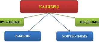
Caliber control rules
3.1. The caliber must be removed from use when its wear reaches the limit established in GOST 24853.
3.2. If disagreements arise in assessing the quality of a product between the manufacturer and the consumer, it is recommended:
3.2.1. When checking a hole or shaft during their manufacture, use new or slightly worn go-through gauges and non-go-through gauges with dimensions close to the smallest for a plug gauge and the largest for a bracket (ring) gauge.
3.2.2. When inspecting a hole or shaft by the manufacturer's inspectors and the customer's representative, use go-through gauges with dimensions close to the permissible wear limit, and no-go gauges with sizes close to the largest for the plug gauge and the smallest for the bracket (ring) gauge.
Digital library
General technical disciplines / Technical measurements / Tolerances of smooth limit gauges (GOST 24852-81, GOST 24853-81)
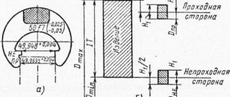
The nominal size of the passage plug is the minimum limit size of the controlled hole (Dmin), the passage bracket is the maximum limit size of the controlled shaft (
dmax).
The nominal size of a no-go plug is the maximum size of the controlled hole (Dmax), a no-go bracket is the minimum size of the shaft (dmin).
Maximum deviations of calibers are measured from the corresponding nominal sizes, i.e. from the maximum dimensions of controlled parts. For pass-through gauges, the wear of which causes a distortion in the nature of the fit, a limit of permissible wear is also established.
When assigning maximum deviations of gauges for holes and shafts with dimensions greater than 180 mm, compensation for control errors caused by elastic deformations of gauges and parts is taken into account.
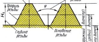
On the diagrams of tolerance fields (Fig. 14.3 and 14.4) and in the formulas for determining caliber sizes, the following designations are used:
Dmax , Dmin _
- maximum hole dimensions;
dmax , dmin _
— maximum shaft dimensions;
H
— approval for the manufacture of plug gauges;
H1
— approval for the manufacture of gauge-clip;
HP
— tolerance of control gauges for staples;
Hs
— tolerance of gauges with spherical measuring surfaces;
Z
— deviation of the middle of the tolerance field for the manufacture of a pass-through plug gauge relative to Dmin;
Z1
— deviation of the middle of the tolerance field for the manufacture of a pass-through gauge-clip relative to dmax;
Y
— permissible exit of a worn-out passage gauge-plug beyond the tolerance zone of the hole, starting from IT9 Y = 0;
Y1
— permissible exit of a worn gauge-clip beyond the tolerance range of the shaft, starting from IT9 Y1= 0;
and is the value for compensating for control errors by calibers, respectively, of holes and shafts with dimensions over 180 mm.
Formulas for calculating the maximum dimensions of working and control gauges are given below.
Working gauges - plugs
(P - PR) max = Dmin + Z + H/2;
(P - PR) min = Dmin + Z – H/2;
(R - PR) purl.
= Dmin – Y (+) – (for sizes greater than 180 mm);
(P - NOT) max = Dmax + H/2 (– ) – (for sizes greater than 180 mm);
(P - NOT) min = Dmax – H/2 (– ) – (for sizes greater than 180 mm).
Working gauges - staples
(P - PR) max = dmax – Z1 + H1/2;
(P - PR) min = dmax – Z1 – H1/2;
(R - PR) purl. = dmax + Y1 (– ) – (for sizes greater than 180 mm);
(P - NOT) max = dmin + H1/2 (+) – (for sizes greater than 180 mm);
(P - NOT) min = dmin – H1/2 (+) – (for sizes larger than 180 mm).
Control gauges
(K - PR) max = d max – Z1 + Hp/2;
(K - PR) min = d max – Z1 – Hp/2;
(K -NOT) max = d min + Hp/2 (+) – (for sizes larger than 180 mm);
(K -NOT) min = d min – Hp/2(+) – (for sizes larger than 180 mm);
(K - I) max = d max +Y1+Hp/2 (– ) – (for sizes larger than 180 mm);
(K - I) min = d max + Y1–Hp/2 (– ) – (for sizes larger than 180 mm).
For sizes up to 180 mm (Fig. 14.3) for pass-through gauges that control holes and shafts of grades 6, 7 and 8, the size of the worn gauge is allowed to exceed the product tolerance range by the value Y,
or
Y1
. For products from 9 to 18 grades, the wear limit of pass-through gauges coincides with the maximum limit of the product material (Y = Y1 = 0).
Numerical values of tolerances and deviations of calibers are selected from the table depending on the quality and nominal size of the controlled product.
For sizes greater than 180 mm (Fig. 14.4), the tolerance field of the non-go gauge and the wear limit of the go gauge are shifted inside the tolerance field of the product by an amount that takes into account the control error of the gauges (a and a1).
TRANSPORTATION AND STORAGE
2.1. For transportation, boxes with calibers must be packed in wooden boxes in accordance with GOST 2991, lined inside with waterproof material.
2.2. Calibers in packaging according to and. 2.1 are transported by all types of transport in covered vehicles in accordance with the rules in force for specific types of transport.
2.3. When transporting, boxes with gauges must be installed so that they cannot be moved. When transporting calibers in containers, the requirements and requirements must be met. 2.1.
2.4. Packaged calibers must be stored in a dry room at a temperature of 10 to 35 ° C and a relative humidity of no more than 80%. There should be no presence of acid and alkali vapors in the air.
Sec. 2. (Changed edition, Amendment No. 1).
SMOOTH NON-ADJUSTABLE CALIBERS Technical requirements
Fixed plain gauges.
Technical requirements GOST
2015-84
MKS 17.040.30 OKP 39 3100
Date of introduction 01/01/85
This standard applies to limiting smooth unregulated gauges (hereinafter referred to as gauges) for testing holes with diameters from 0.1 to 360 mm and shafts with diameters from 1 to 360 mm, with tolerances in accordance with GOST 25347 and the OST system.
Requirements section. 2a, 2, 3 and pi. 1.1—1.21; 1.23; 1.25 are mandatory, other requirements of this standard are recommended.
(Changed edition, Amendment No. 1).
FORMULAS FOR DETERMINING PERFORMANCE SIZES OF CALIBERS
3.1. The executive dimensions of the calibers must be determined according to the formulas indicated in Table 1.
Table 1
| Caliber | Nominal size of the product, mm | ||||||||
| up to 180 | St. 180 to 500 | ||||||||
| Working caliber | Reference caliber | Working caliber | Reference caliber | ||||||
| Size | Tolerance | Size | Tolerance | Size | Tolerance | Size | Tolerance | ||
| For hole | Passage side is new | — | — | or | — | — | |||
| Passage side worn | — | — | — | — | — | — | |||
| Non-passable side | or | — | — | or | — | — | |||
| For shaft | Passage side is new | ||||||||
| Passage side worn | — | — | |||||||
| Non-passable side | |||||||||
Note. When calculating the executive dimensions of gauges (the largest for holes and the smallest for shafts), it is necessary to use the following rounding rules:
rounding of the sizes of working calibers (the largest for the hole and the smallest for the shafts) for products of grades 15-17 should be done to the whole micrometer;
for products of grades 6-14 and all control calibers, dimensions should be rounded to multiples of 0.5 microns, while the tolerance for calibers is maintained;
dimensions ending in 0.25 and 0.75 microns should be rounded to multiples of 0.5 microns in the direction of decreasing the manufacturing tolerance of the product.
THREAD PROFILE AND LENGTH OF THE WORKING PART OF CALIBERS
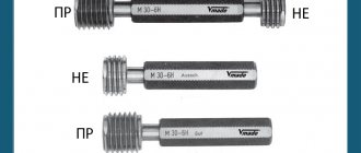
3.1. Plug gauges of type PR (21) must have a full thread profile in accordance with that indicated in Figure 1a, ring gauges of type PR (1) and clamp gauges of type PR (7) - in accordance with that indicated in Figure 2a.
Damn.1
* Does not apply to caliber type PR (7).
Damn.2
3.2. The full thread profile of gauges of types PR (21), PR (1) and PR (7) must have a radius r at the tops and bottoms of the thread. The values of radii r related to the nominal thread profile must correspond to those indicated in Table 1.
Table 1
Dimensions in mm
| P | Number of steps per length 25.4 mm | b1, no more | u=0.14784P | r, no more |
| 0,907 | 28 | 0,20 | 0,134 | 0,125 |
| 1,337 | 19 | 0,30 | 0,198 | 0,184 |
| 1,814 | 14 | 0,40 | 0,268 | 0,249 |
| 2,309 | 11 | 0,50 | 0,341 | 0,317 |
Note. The radius r is the initial one for designing a thread-forming tool and is not subject to mandatory control.
3.3. It is allowed to produce plug gauges of type PR (21) with a profile in accordance with that indicated in Figure 1b, ring gauges of type PR (1) and clamp gauges of type PR (7) - in accordance with that indicated in Figure 2b, having vertices , cut along a chord passing through the tangent points of the circular arc of the rounded thread profile according to GOST 6357 by the value u/2 and with a groove width b1.
The numerical values of u and b1 must correspond to those indicated in Table 1. The value u is for reference, serves to calculate diameters at the thread tips and is not subject to direct control. The groove shape is arbitrary.
Note. The dimensions of the thread glands of products (the outer diameter of the internal thread and the internal diameter of the external thread) are not controlled by a gauge with a cut off top.
3.4. Plug gauges of the types KPR-PR (2), U-PR (8), U-NE (10), KNE-PR (12), KNE-NE (13) and KI-NE (16) must have a thread profile with cut off tops and with a radius r along the grooves of the thread in accordance with that indicated in Figure 3. The dimensions of the radii r must correspond to the values indicated in Table 1.
Notes:
1. The value of the cut of the thread tips is determined by the formulas for calculating the outer diameter of the gauges indicated in Table 9.
2. The dimensions of the thread recesses of the pass-through ring gauge type PR (1) are not controlled by the plug gauge type KPR-PR (2) with a cut off top.
Damn.3
3.5. Plug gauges of types KPR-NE (3), K-I (6) and HE (22) must have a shortened thread profile in accordance with that shown in Fig. 4, ring gauges of type HE (11) and clamp gauges of type HE (9) - in accordance with what is indicated in Figure 5.
Damn.4
* Does not apply to caliber type HE (9).
Damn.5
The shortened thread profile of the gauge must be made with groove b3 and dimensions F1 and F3 indicated in Table 2. The groove shape is arbitrary.
table 2
Dimensions in mm
| P | Number of steps per length 25.4 mm | F1=0.1P | b3 | F3 | |
| Nom. | Prev. off | ||||
| 0,907 | 28 | 0,091 | 0,25 | ±0,03 | From 0.20 to 0.35 |
| 1,337 | 19 | 0,134 | 0,40 | ±0,04 | 0,30 » 0,50 |
| 1,814 | 14 | 0,181 | 0,50 | ±0,05 | 0,40 » 0,70 |
| 2,309 | 11 | 0,231 | 0,80 | ±0,05 | 0,40 » 0,70 |
The F1 value is for reference; it is used to calculate the diameters at the thread tips of gauges with a shortened profile and is not subject to direct control.
3.6. The displacement S of the groove relative to the sides of the thread profile (Fig. 6) should be no more than the maximum deviation of the groove width b3 specified in Table 2.
1 - actual position of the groove axis; 2 - nominal position of the groove axis Figure 6
The maximum deviation of the groove width b3 can be increased by twice the difference between the limit and actual values of the displacement S, if the actual value is less than the limit.
Note. Instead of size b3 and offset S, it is possible to control the height F3 (Fig. 4).
3.7. The thread length of the working part of thread gauges must be no less than the values indicated in Table 3.
Table 3
| Designation (type number) of the caliber | Thread length of the working part of the caliber, mm |
| PR (1) | 0.8Nk |
| KPR-PR (2) | 0.8Nk+P |
| KPR-NOT (3) | 3P |
| K-I (6) | 3P |
| PR (7) | 0.8Nk |
| U-PR (8) | 0.8Nk+P |
| NOT (9) | In accordance with Table 9 and Figure 7 |
| U-NE (10) | 3P |
| NOT (11) | 3P |
| KNE-PR (12) | 3P |
| KNE-NE (13) | 3P |
| KI-NE (16) | 3P |
| PR (21) | 0.8Nk |
| NOT (22) | 3P |
Note. For make-up lengths L according to GOST 6357, the thread length of the working part of the pass-through gauges must be at least 0.8 of the make-up length of the thread.
Damn.7
3.8. The length of the working part of smooth gauges for monitoring the outer diameter of the external thread and the internal diameter of the internal thread must be no less than the values specified in Table 4.
Table 4
| Designation (type number) of the caliber | Length of the working part of the caliber, mm |
| PR (17) | 3P (for clamp gauge) |
| 0.8Nk (for ring gauge) | |
| NOT (18) | 3P |
| K-PR (19) | 3P |
| K-NOT (20) | 3P |
| PR (23) | 0.8Nk |
| NOT (24) | 3P |
| K-I (25) | 3P |