GOST 1139-80
Group G14
INTERSTATE STANDARD
Basic norms of interchangeability
STRAIGHT SPLINE CONNECTIONS
Dimensions and tolerances
Basic norms of interchangeability. Straight-sided splined joints. Dimensions and tolerances
ISS 21.120.30
Date of introduction 1982-01-01
INFORMATION DATA
1. DEVELOPED AND INTRODUCED by the State Committee on Standards
2. APPROVED AND ENTERED INTO EFFECT by Resolution of the State Committee on Standards dated 03.06.80 N 2516
3. The standard fully complies with ST SEV 6844-89
4. The standard complies with ISO 14-1982 in terms of nominal dimensions and tolerance fields when centering along the internal diameter
5. INTRODUCED FOR THE FIRST TIME
6. REFERENCE REGULATIVE AND TECHNICAL DOCUMENTS
| Designation of the referenced technical document | Item number, application |
| GOST 1139-58 | 2.8 |
| GOST 24960-81 | Appendix 2 |
| GOST 24961-81 | Appendix 2 |
| GOST 24962-81 | Appendix 2 |
| GOST 24963-81 | Appendix 2 |
| GOST 24964-81 | Appendix 2 |
| GOST 24965-81 | Appendix 2 |
| GOST 24966-81 | Appendix 2 |
| GOST 24967-81 | Appendix 2 |
| GOST 24968-81 | Appendix 2 |
| GOST 25346-89 | 2.1 |
7. The validity period was removed by Decree of the State Standard of October 26, 1990 N 2695
8. EDITION with Amendments No. 1, 2, approved in January 1982, October 1990 (IUS 3-82, 1-91)
An amendment was made, published in IUS No. 9, 2011
Amendment made by database manufacturer
This standard applies to general-purpose spline joints with a straight-sided profile of teeth located parallel to the axis of the connection and with the lateral sides of the profile parallel to the symmetry axis of the spline outside the diameter circle, and establishes the number of teeth, nominal dimensions of connections of the light, medium and heavy series, as well as tolerances for connections with centering along the inner diameter, along the outer diameter and on the sides of the teeth.
The standard does not apply to special spline connections that differ from those regulated by this standard in nominal dimensions and type of centering.
The standard does not apply to products designed before 1980.
The standard fully complies with the standards of ST SEV 6844-89.
(Changed edition, Amendment No. 2).
Characteristics of spline connections
According to their design and method of transmitting torque, spline joints can be classified as multi-keyed. Several planes of interaction during rotation, but instead of a large number of grooves and keys in them, there is only a splined shaft and bushing. There are no keys; they are replaced by slotted grooves and teeth cut directly on the mating parts. The design can significantly reduce manufacturing errors and makes it possible for the sleeve to move along the shaft axis without stopping the radial movement.
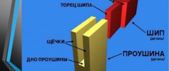
Spline joints include a shaft with teeth evenly distributed across the diameter and a mating sleeve with mating grooves.
The dimensions of the splines are determined by the internal diameter of the shaft, their number and shape. In a spline connection, several contact planes are formed. The ability to transmit high torque increases several times compared to keys.
The spline tooth is cut with cutters on gear cutting machines and by broaching. For moving units, subsequent grinding of the side surfaces is done. The length of the teeth can be any; for fixed spline joints it is equal to the height of the wheel hub. When the gear slides along the axis, the length of the cut protrusions on the shaft is determined by the size of the gear movement, its height and the technological allowance equal to the radius of the cutter for its exit during processing.
The diameter of the shaft along the outer surface is equal to the size of the sleeve along the depressions. The splined bushing exactly copies the shaft profile with its hole and fits tightly onto it. Spline grooves along the hole are cut on a slotting machine. The manufacturing technology is lengthy and requires great precision, which a cutter cannot provide, since the length of the cutter is large relative to its cross-section. When you try to speed up processing, make more entry and feed, the tool is pressed out, the size turns out to be minus.
When designing a unit and selecting pairs, the main parameter is the internal diameter of the splines. It is designed for torsion and bending. The splined bushing is subjected to less force. It is selected from the directory. The parts are made from medium-carbon low-alloy steels: St 45, St 40Х, St 40ХН. They have relatively high toughness and low brittleness in the normalized state and after volumetric hardening in air with a hardness of 320–350 HB.
The number of teeth during design can be determined using tables. They are divided for each internal diameter into 3 groups according to loads:
- light;
- average;
- heavy.
The more torque you need to transmit, the higher the spline itself and the greater their number. Due to this, the contact area increases.
Gear connections are calculated taking into account manufacturing errors. There is a connection gap between the surfaces of the mating parts. When the driving part is rotated, it moves in the opposite direction from the direction of the force. Ideally, all surfaces are in contact and loaded equally. In fact, gear joints are manufactured with an error of 0.01–0.03 mm, depending on the size and processing method. The coupling touches more with one plane and less with others. When calculating strength, a correction factor is selected from the table, which allows you to calculate the parameters of parts for strength, taking into account uneven load forces.
The gap in the connection determines the size of the idle stroke. Starting to move, the leading part first selects a gap between the working planes, then the force action and rotation of the driven part and the entire assembly begins.
Table of contents
1 Initial contour and shape of teeth
2 Nominal diameters, modules and numbers of teeth
3 Limit deviations from parallelism of the sides of the teeth of the shaft and sleeve
4 Nominal sizes and measured values
5 Tolerances and fits
6 Conventions
7 Control methods
Appendix 1 Selection of parameter values for spline connections HF and hf depending on the type of tool used
Appendix 3 Tolerances and fits when centering along the internal diameter
Appendix 4 Calculation of maximum deviations and control dimensions
×
| Date of introduction: | 01.01.1982 |
| Added to the database: | 01.09.2013 |
| Update: | 01.01.2019 |
This GOST is located in:
Section: Ecology
Subsection: 21 MECHANICAL SYSTEMS AND GENERAL PURPOSE DEVICES
Subsection: 21.120 Shafts and couplings
Subsection: 21.120.30 Keys, keyways, splines
Section: Electricity
Subsection: 21 MECHANICAL SYSTEMS AND GENERAL PURPOSE DEVICES
Subsection: 21.120 Shafts and couplings
Subsection: 21.120.30 Keys, keyways, splines
Read also: DIY hydraulic press from a jack video
Classification
The details of the spline units are normalized - there is a specific list of standard sizes, with corresponding pairs. Tools are made for them and equipment is adjusted. Depending on operating conditions and loads, spline connections are divided into several groups. They are characterized by:
- tooth shape;
- base surfaces;
- possibility of displacement along the axis.
The shape of the protrusion is determined by the spline shaft. The bushing has only corresponding cutouts - grooves. The characteristics are determined by the types of splines:
- straight or straight-sided;
- involute;
- triangular.
The classification is made by the shape of the tooth in cross-section across the joint.
Straight-sided - straight-toothed
In straight-sided spline joints, the tooth in cross section is a rectangle. The width is the same throughout the entire height. They are most often found in mechanisms, since production is relatively simple. Straight-toothed spline connections are distinguished by load size: low, medium, high.
Depending on the method of movement along the axis, the types of connections are distinguished:
- one-piece;
- movable without load;
- movable under load.
One-piece ones are used in gearboxes and other components when transmitting rotation between a permanent pair of parts.
An example of moving joints without load are machine tool gearboxes. When switching, the shaft moves and another pair engages. The gear ratio and rotation speed of the chuck or spindle changes.
The car's gearbox does not require a complete stop to shift. The bushing moves relative to the axis of rotation without stopping, under load.
The classification of spline joints also includes the method of alignment. He can be:
- by internal diameter – d;
- by outer diameter – D;
- on the sides, tooth width – b.
When centering along the inner diameter, minimum manufacturing tolerances are given for the size of the shaft along the cavity and the inner diameter of the sleeve. A gap is formed between the top of the tooth on the shaft and the bottom of the spline. The accuracy of the connection is achieved by grinding the sleeve hole on an internal grinding machine. Processing of a smaller diameter on the shaft is carried out with an abrasive wheel along the axis.
When centering along the outer diameter, a tight fit occurs along the top of the protrusion on the shaft and the diameter along the depression on the sleeve. In this case, external grinding of the shaft and finishing are performed - slotting, bushings.
Centering, or more precisely, landing on the side surfaces, is possible only for permanent connections, when it is necessary to eliminate idling at the beginning of movement.
The splines are manufactured with high precision according to the width of the tooth and its location relative to the axis. The sleeve is pressed onto the shaft. There are gaps along both diameters.
The drawing shows a cross-section of the connection with one tooth and the diameters in dotted lines. The sleeve is shaded. In the main view, straight-toothed spline connections are indicated by the extension of a line with characteristics. The decoding includes the letter designation of the alignment method, the number and width of the splines, the size of the internal and external diameters, indicating the accuracy class and finish of all surfaces.
Involute
The connection got its name from the shape of the side surface in the form of an involute, like a cylindrical gear. The large contact area and wide tooth at the base allows for the transmission of enormous force. The tooth has high bending strength.
Spline shafts are made on gear hobbing machines. High accuracy is obtained using standard equipment. Centering is done along the outer diameter for mechanisms operating with high precision, and along the side surface for heavily loaded units. The connection is fixed. With lateral displacement, a large friction force occurs.
The drawing shows one tooth and its shape, by analogy with spur gears. In addition to the diameters and processing class, the GOST according to which the splines were manufactured is indicated under the extension line.
Triangular profile
To transmit rotation through thin-walled hubs, spline connections with a triangular profile are made. They are connected motionlessly and are used for low-power forces that require high precision rotation transmission.
The tooth is manufactured according to industry standards with an angle of 30°, 36° and 45°. The teeth are small, the number is large, ranging from 20 to 70 pcs. Centering is carried out only on the side surfaces.
They are located on the windshield wiper drive in cars, torsion shafts of trimmers.
Other GOSTs
GOST 25096-82 Basic standards of interchangeability. The thread is persistent. Tolerances GOST 10177-82 Basic standards of interchangeability. The thread is persistent. Profile and main dimensions GOST 11708-82 Basic norms of interchangeability. Thread. Terms and definitions GOST ISO 965-5-2015 Basic standards of interchangeability. Metric ISO threads for general purpose. Tolerances. Limit dimensions of internal threads mating with hot-dip galvanized external threads corresponding to tolerance fields with basic deviations up to h inclusive before coating GOST 24071-97 Basic standards of interchangeability. Segment keys and keyways GOST 25307-82 Basic norms of interchangeability. System of tolerances and fits for conical joints GOST 1139-80 Basic standards of interchangeability. Straight-sided spline connections. Dimensions and tolerances GOST 24070-80 Basic standards of interchangeability. Keyed connections with tangential reinforced keys. Dimensions of sections of keys and grooves. Tolerances and landings GOST 24069-80 Basic standards of interchangeability. Keyed connections with tangential normal keys. Dimensions of sections of keys and grooves. Tolerances and landings GOST 24071-80 Basic standards of interchangeability. Keyed connections with segment keys. Dimensions of keys and groove sections. Tolerances and landings GOST 23360-78 Basic standards of interchangeability. Keyed connections with parallel keys. Dimensions of keys and groove sections. Tolerances and landings GOST 8790-79 Basic standards of interchangeability. Keyed connections with prismatic guide keys secured to the shaft. Dimensions of keys and groove sections. Tolerances and landings GOST 10748-79 Basic standards of interchangeability. Keyed connections with prismatic high keys. Dimensions of keys and groove sections. Tolerances and landings GOST 24068-80 Basic standards of interchangeability. Keyed connections with wedge keys. Dimensions of keys and groove sections. Tolerances and landings
Advantages and disadvantages
When designing mechanisms that transmit rotation with high loads, they most often choose a splined connection. It has enormous advantages in certain cases and can replace several keyed joints. There are also disadvantages. It is necessary to weigh all the arguments for and against when choosing a connection method.
Compared to keys, the advantages of spline connections include:
- reliability under shock loads and vibration;
- possibility to reduce the length of the hub;
- small radial clearances;
- increase in service life;
- no shear load and low bending load due to the large contact patch;
- several lines of application of forces, the ability to transmit large forces by shafts with a small diameter;
- axial movement;
- there are only 2 parts in the connection;
- compactness;
- precise alignment.
The splines are manufactured in accordance with GOST and Standards, have strictly standardized dimensions and the parts for the connection are easy to select. Simplified assembly of components and fitting of parts.
The disadvantages of spline connections include:
- high cost of parts;
- complex manufacturing technology;
- use of special equipment and tools.
When overloaded, the key is simply cut off, preventing the transfer of increased load to the working mechanism and preventing its breakage. The part is simple and cheap, easy to change.
In spline joints, in an emergency, a tooth or the entire machine may break. Replacing parts is difficult and expensive.
Application
The need to use gear connections arises when it is necessary to transmit large torque and high demands are placed on the alignment of the driving and driven parts and the accuracy of movement. Splines allow the bushing to move along the axis, changing the gear ratio without stopping the mechanism. Due to this, they are used in gearboxes of cars, machine tools, and loading units.
The purpose of the spline, like the key, is to transmit torque at a given angular velocity.
The load distribution relative to the axis of rotation is uniform, according to the number of teeth, radial runout is eliminated. This is used in precision instruments where precision is required.
Rotation using triangular teeth is found in household appliances and power tools:
- mixers;
- lawnmowers;
- drills;
- robot vacuum cleaners.
In all areas of mechanical engineering, machine tool construction, machines and other vehicles, a compact and powerful rotation transmission unit is used.
