Classification of calibers
Gauges are means of measurement control designed to verify compliance of the actual dimensions, shape and arrangement of surfaces of parts with the specified requirements.
Gauges are used to control parts in mass and serial production.
Normal caliber is an unambiguous measure that reproduces the average value (the value of the middle of the tolerance field) of the controlled size. When using a normal gauge, the suitability of the part is judged, for example, by the gaps between the surfaces of the part and the gauge, or by the “tightness” of the resulting interface between the controlled part and the normal gauge.
Limit gauge - a measure or set of measures that ensures control of the geometric parameters of parts according to the highest and lowest limit values. Limit gauges are made to check the dimensions of smooth cylindrical and conical surfaces, the depth and height of ledges, and the parameters of threaded and splined surfaces of parts. Gauges are also made to control the location of surfaces of parts, standardized by positional tolerances, alignment tolerances, etc.
When testing by limit gauges, a part is considered suitable if the pass gauge passes under the influence of gravity, and the non-go gauge does not pass through the controlled element of the part.
According to their technological purpose, gauges are divided into working gauges used to control products during the manufacturing and acceptance of finished products and control gauges (counter gauges) to check working gauges.
Based on the number of controlled elements , a distinction is made between complex gauges, which simultaneously control several elements of a product (for example, a threaded pass gauge) and simple (elemental) gauges, which check one element (size) of a product.
Based on the nature of contact with the product, calibers are distinguished with surface contact (plug), with linear contact (clip) and point contact (bore gauge).
Based on their design characteristics, they distinguish between single-limit gauges with separate execution of pass-through and non-go-through gauges, and double-limit (one-sided and double-sided) gauges, which represent a constructive combination of pass-through and non-go-through gauges.
Pass-through gauge (PR) , the nominal size of which is equal to the largest maximum shaft size or the smallest maximum hole size;
No-go gauge (NOT) , the nominal size of which is equal to the smallest limit shaft size or the largest limit hole size.
Gauge for inspection of small diameter holes and shafts
Cone inspection gauges
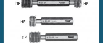
Thread inspection gauges
Templates
The design of smooth gauges is based on the Tylor principle or the principle of similarity, according to which the passage gauges should be a prototype of the mating part and comprehensively control all types of errors of a given surface (checking the diameter and shape errors, including deviations from the straightness of the hole axis).
This ensures the assembly of the compound. Non-go gauges must provide element-by-element control (control of the actual dimensions), therefore, the contact between the working surfaces of the gauges and the controlled surface must be point-like.
that fully complies with the Taylor principle for checking a hole must have a pass side in the form of a cylinder with a length equal to the length of the mating or controlled surface (full plug), and a non-pass side in the form of an incomplete plug in the form of a rod with spherical tips. The working gauge for shaft control must have a pass side in the form of a ring with a length equal to the length of the mating or controlled surface, and a non-pass side in the form of a bracket with knife surfaces.
Basic requirements for calibers:
- precision manufacturing;
- high rigidity with low weight;
- wear resistance;
- productivity and ease of control;
- constancy of working dimensions over time;
- corrosion resistance.
Calibers, types and purpose. Control of macrogeometry parameters of parts using gauges
Gauges are means of measurement control designed to verify compliance of the actual dimensions, shape and arrangement of surfaces of parts with the specified requirements.
Gauges are used to control parts in mass and serial production. Calibers are normal and extreme.
Normal caliber is an unambiguous measure that reproduces the average value (the value of the middle of the tolerance field) of the controlled size. When using a normal gauge, the suitability of the part is judged, for example, by the gaps between the surfaces of the part and the gauge, or by the “tightness” of the resulting interface between the controlled part and the normal gauge. Gap assessment, therefore, control results largely depend on the qualifications of the inspector and are subjective.
Limit gauges - a measure or set of measures that ensures control of the geometric parameters of parts according to the highest and lowest limit values. Limit gauges are made to check the dimensions of smooth cylindrical and conical surfaces, the depth and height of ledges, and the parameters of threaded and splined surfaces of parts. Gauges are also made to control the location of surfaces of parts, standardized by positional tolerances, alignment tolerances, etc.
When testing by limit gauges, a part is considered suitable if the pass gauge passes under the influence of gravity, and the non-go gauge does not pass through the controlled element of the part. The control results are practically independent of the operator’s qualifications.
By design, gauges are divided into plugs and staples. To control holes, plug gauges are used, and to control shafts, clamp gauges are used.
Based on their purpose, calibers are divided into working and control.
Working gauges are designed to control parts during their manufacture and acceptance. Such calibers are used at enterprises by workers and inspectors of technical control departments (QCD). Control gauges are used to control rigid working limit gauges or to adjust adjustable working gauges.
The set of working limit gauges for testing smooth cylindrical surfaces of parts includes:
— a pass-through gauge (PR), the nominal size of which is equal to the largest limit size of the shaft or the smallest limit size of the hole;
- no-go gauge (NOT), the nominal size of which is equal to the smallest maximum shaft size or the largest maximum hole size.
The design of smooth gauges is based on the Taylor principle or the principle of similarity, according to which the passage gauges should be a prototype of the mating part and comprehensively control all types of errors of a given surface (checking the diameter and shape errors, including deviations from the straightness of the hole axis). This ensures the assembly of the compound. Non-go gauges must provide element-by-element control (control of the actual dimensions), therefore, the contact between the working surfaces of the gauges and the controlled surface must be point-like.
that fully complies with the Taylor principle for checking a hole must have a pass side in the form of a cylinder with a length equal to the length of the mating or controlled surface (full plug), and a non-pass side in the form of an incomplete plug in the form of a rod with spherical tips. The working gauge for shaft control must have a pass side in the form of a ring with a length equal to the length of the mating or controlled surface, and a non-pass side in the form of a bracket with knife surfaces. In practice, due to the peculiarities of manufacturing and control technology, a violation of the Taylor principle is often observed, for example, gauges for testing small diameter holes are made in the form of full plugs, and for testing shafts - in the form of brackets.
Control of the size of the holes is usually carried out with go-through and no-go gauges-plugs inserted into a common handle (Fig. 3.77 a).
Calibers for shafts are usually made in the form of brackets with plane-parallel working surfaces (Fig. 3.77 b).
A
| b | V |
Rice. 3.77. Sketches of calibers
If the go and no-go gauges for checking holes are made in the form of full plugs, then the no-go plug has a shorter length than the go-through one. For holes of large diameters, gauges with working surfaces in the form of an incomplete plug are more often used, for example, a sheet plug with cylindrical working surfaces, and the length of the working surfaces of a non-go-through plug is significantly less than that of a go-through plug. Each plug controls several cross sections of the hole (at least two mutually perpendicular sections are controlled).
When inspecting shafts with a clamp gauge , the surface is checked in several sections along the length and in at least two mutually perpendicular directions of each section.
If the parts are suitable, then, in accordance with the name, go-through gauges (PG) should pass through the controlled surfaces under the influence of their own weight, and non-go-through gauges (NOT) should not pass through.
When inspecting smooth gauges , a number of rules must be followed, in particular, use only gauges intended for this case (workers, as a rule, use new pass gauges, quality control workers can use partially worn gauges). It is necessary to ensure the cleanliness of the measuring surfaces, do not try to push pass and no-go gauges by force, and in order to avoid heating, do not hold the gauges in your hands longer than necessary.
The types of smooth non-adjustable gauges for monitoring cylindrical holes and shafts are established by GOST 24851-81, in which their various design types are assigned numbers (1...12) and corresponding names.
There are three versions of smooth calibers:
1. Single-limit plugs or staples (go-through, marked PR, and non-go-through - NOT), used primarily for the control of relatively large sizes.
2. Double-limit double-sided gauges, which speed up control somewhat. They are designed for relatively small sizes: staple gauges up to 10 mm and plug gauges up to 50 mm.
3. Single-sided double-limit gauges, which are more compact and almost double the speed of control. These gauges are available for a wide range of sizes.
Single-sided staples , starting with sizes over 200 mm for controlling shafts up to the 8th grade inclusive, must be equipped with heat-insulating handles.
Structurally smooth gauges can be made adjustable or non-adjustable.
Calibers for sizes over 500 mm, according to GOST 24852-81, are used only for testing parts of 9...17 qualifications. These calibers have a single layout of tolerance fields.
The calculation of calibers comes down to determining the executive dimensions of the measuring surfaces, limiting the deviations of their shape and assigning the optimal roughness. The starting point for deviations for passing smooth gauges is the passing limit of the shaft or hole, for non-passing gauges - their non-passing limit. For pass-through gauges, in addition to the manufacturing permit, a permissible wear limit is also provided separately.
For productive and accurate control of the internal dimensions of the control gauges-clips during their finishing during manufacturing and for quickly determining the moment of complete wear, smooth control gauges are used (Fig. 3.77 c).
The set of control gauges includes three gauges made in the form of washers:
— control passage gauge (K-PR);
— control no-go gauge (K-NOT);
— gauge for monitoring the wear of the pass gauge (CI).
The control calibers K-PR and K-NE, due to the small tolerances of the working calibers for which they are intended to control, are made as normal, and not limiting calibers, and the suitability of the working calibers is determined using a subjective assessment of the compliance of the checked sizes with the control calibers.
The CI gauge is designed to control the permissible wear of the pass side and can be considered as a limit gauge that controls the limit of permissible wear.
Control gauges (for sizes up to 180 mm, blocks of gauge blocks can also be used) are designed to speed up checking the final dimensions of the pass and non-go sides when manufacturing non-adjustable or installing adjustable brackets (K-PR and K-NE), as well as to control the moment of complete wear of the pass-through staple gauges during their operation (CI).
Gauges for checking plug gauges are not manufactured. The dimensions of plug gauges are checked using universal measuring instruments, which is not difficult for external surfaces.
Manufacturing tolerances are established for all gauges, and for a pass gauge, which wears out more intensively when inspecting a part, a wear limit is additionally set.
Tolerances on the measuring surfaces of smooth gauges are established by GOST 24853-81 (for sizes up to 500 mm) and GOST 24852-81 (for sizes from 500 mm to 3150 mm). The tolerances of the working surfaces of the gauges are significantly less than the tolerances of the parts for which they are intended to control, and have been tested by many years of practice.
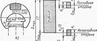
To construct layout diagrams of tolerance fields, it is necessary to determine the nominal dimensions of the gauges, which correspond to the maximum dimensions of the surface of the hole or shaft controlled by the gauge (Fig. 3.78).
The location of the caliber tolerance fields according to GOST 24853-81 depends on the nominal size of the part (the schemes differ for sizes up to 180 mm and over 180 mm and for qualifications 6, 7, 8 and from 9 to 17).
Rice. 3.78. To determine the nominal sizes of calibers
The standard establishes the following standards for calibers:
— N – tolerance for the manufacture of gauges for the hole;
— Нs – tolerance for the manufacture of gauges with spherical measuring surfaces (for a hole);
— H1 – tolerance for the manufacture of shaft gauges;
— Нр – approval for the manufacture of a control gauge for the staple.
The wear of pass-through gauges is limited to the following values:
— Y is the permissible deviation of the size of a worn-out pass gauge for a hole beyond the tolerance zone of the product;
— Y1 is the permissible deviation of the size of the worn-out pass-through gauge for the shaft beyond the tolerance zone of the product.
For all pass-through gauges, the tolerance fields are shifted inside the tolerance field of the part by the Z value for plug gauges and the Z1 value for staple gauges. This arrangement of the tolerance field of a pass-through gauge, subject to wear, makes it possible to increase its durability, although it increases the risk of rejection of suitable parts by a new gauge.
The executive size is the size of the caliber for which the caliber is made. When determining the executive size of a caliber, the nominal size is replaced: the maximum limit of the caliber material with the location of the tolerance field “into the body” of the part is taken as the “new” nominal size. In the drawings of working plug gauges and control gauges, the largest size with a negative deviation equal to the width of the tolerance field is indicated; for clamp gauges, the smallest size with a positive deviation.
Gauges are widely used for testing complex surfaces of parts, including spline and threaded surfaces. In this case, to design the working surfaces of calibers, the Taylor principle must be used.
For example , to control spline bushings, the working pass gauge is made in the form of a spline shaft, which allows you to simultaneously control the dimensions of the outer and inner diameters of the spline bushing, as well as the relative position of the outer and inner cylindrical surfaces of the bushing, the pitch and direction of the splines, and the width of the depressions. To control the no-go limits (limits for the minimum material of the part), a set of no-go gauges is used to check the actual dimensions of the spline bushing elements. The diameters are controlled by plugs, with an incomplete or full plug used for the internal diameter, and an incomplete plug used for the outer diameter of the spline bushing. The kit also includes a working gauge for checking the width of the slots.
To control the thread, use a working threaded plug with a full profile thread and a length equal to the length of the threaded mate. The set of no-go gauges includes a working no-go thread gauge with a shortened thread profile and reduced length of the threaded part, as well as smooth gauges for controlling the diameter of the protrusions. A no-go thread gauge should be screwed onto the mating piece by no more than one and a half turns.
Standardization of caliber accuracy standards
The nominal dimensions of the gauges must correspond to the maximum dimensions of the part. The executive dimensions of calibers are the maximum dimensions by which new calibers are made and the wear of calibers in service is checked.
For plugs, indicate the largest maximum size and manufacturing tolerance “minus”, and for staples - the smallest maximum size with a tolerance “plus”.
For working pass-through gauges, the maximum size of the worn gauge is additionally indicated.
The executive dimensions of the calibers are determined by algebraically summing the maximum size of the product with the corresponding maximum deviation.
Depending on the degree of wear, calibers are divided into:
- new – working calibers;
- partially worn – controller calibers;
- worn to the established limit - acceptance gauges.
N – tolerance for the manufacture of gauges for holes;
Нs – tolerance for the manufacture of gauges with spherical measuring surfaces (for a hole);
H1 – tolerance for the manufacture of shaft gauges;
HP – approval for the manufacture of a control gauge for the staple.
Y – permissible output of the size of the worn-out pass gauge for the hole
Y1 – permissible output of the size of the worn-out pass-through gauge for the shaft.
About calibers
BASIC CONCEPTS CONSTRUCTION OF CALIBERS Sheet corks, incomplete and partial corks Smooth full corks Limit gauges Gauge for measuring shafts Gauge for changing lengths and heights Gauge for conical surfaces TOLERANCE SYSTEM FOR LIMIT GAUGE USE OF GAUGE
BASIC CONCEPTS
Calibers are those measuring instruments that are used to check the correctness of the dimensions and shape of products and with the help of which it is possible to establish that the manufactured products will fit together in an assembly and that this connection of products will be of the required quality.
Gauge gauges are designed primarily to measure one specific size. They do not allow you to measure the actual size of the product, but only make it possible to establish that the product has not gone beyond the boundaries indicated in the drawing - the tolerances for its manufacture.
Double-sided plug gauges
Calibers are normal and extreme. Normal calibers have one size, the one that is desirable to obtain on the product. The suitability of a product is determined by the inclusion of a caliber with a greater or lesser degree of density. The use of normal calibers requires great qualifications and experience of the worker and controller.
Limit gauges have two sizes: one gauge size is equal to the smallest limit size of the part, the second is equal to the largest. One end of the gauge must fit into the part, but the other must not. One of these sizes is called pass-through, the other non-pass-through, or larger and smaller. The use of extreme calibers ensures complete interchangeability of parts and does not require highly qualified workers and inspectors.
Interchangeability is the ability of parts to be assembled with each other with the required fit without fitting the parts in place.
Currently, mainly limit calibers are used. Normal calibers are used much less frequently. They are used only as control gauges, as well as for checking the profile surfaces of products. Smooth gauges are used to measure hole diameters, shaft diameters, lengths and heights.
Double-sided clamp gauge
Limit gauges for holes are called plug gauges and are a rod with two cylinders. One cylinder has the smallest maximum hole size and is called the go-through end, the second has the largest maximum size and is called the non-go-through end of the caliber.
The limit gauges for shafts are clamp gauges. One end of the bracket is passable, the other is non-passable. The size of the through side is equal to the largest maximum shaft size, the size of the non-through side is equal to the smallest maximum shaft size.
When measuring, go-through plug gauges should fit freely into the hole, while non-go-through gauges should not enter the hole completely, but only “bite”. If a no-go gauge fits into the hole, this means that a defect has been made. The pass-through brackets must be placed on the shaft under the influence of their own weight. No-go staples should not be put on the shaft. If a no-go staple is put on the shaft, the shaft is rejected.
The maximum dimensions of the products for which the gauges are intended are called the nominal sizes of the gauges.
The actual dimensions of the calibers differ from the nominal sizes because: 1) calibers cannot be manufactured with absolute precision; 2) during use they wear out and change their size; 3) their purpose is different: they are used either to control the product, or to control the calibers themselves.
Calibers for product control are called working gauges. The gauges used to control gauge sizes are called reference gauges or counter gauges. Types of calibers, tolerances for their manufacture and wear are established by state standards and are called the tolerance system for maximum calibers.
Caliber (French caliber, caliber limites) is a scale-free tool used for controlling the dimensions, shape and mutual adjustment of the surface of a part (threaded gauge-plug, threaded gauge-ring, smooth caliber-plug, calibers face).
Calibers are borderline and normal. A normal gauge (template) is used to check folding profiles. The boundary gauge has a passing and non-passing side (upper and lower division of the nominal size), which allows you to control the size within the tolerance field. Boundary gauges are designed for a variety of cylindrical, conical, threaded and splined surfaces. When designing boundary gauges, the Taylor principle must be followed, whereby the pass-through gauge is the prototype of the mating part and controls the size throughout the entire connection with the correction of shape errors. The non-passing gauge is required to control only the size of the part and therefore has little effort to eliminate the influx of shape defects.
Types of boundary gauges: clamp gauge, plug gauge, threaded plug gauge, threaded ring gauge, etc.
DESIGN OF CALIBERS
When developing and selecting gauge designs, one should proceed from the basic principle of designing measuring instruments - the principle of similarity. The essence of this principle is that the pass side of the gauge should be similar in shape to the mating part and limit all elements of the product, and the non-pass side should test individual limited sections or sections of the product being tested.
Based on this principle, for example, you should check the shaft with a ring and a no-go bracket, and the hole with a go-through cylindrical plug and a no-go incomplete plug.
Gauges for monitoring holes are made in the form of: 1) smooth full plugs; 2) incomplete sheet corks and incomplete corks; 3) spherical gauges and bore gauges; 4) conical plugs.
INCOMPLETE SHEET CORKS AND INCOMPLETE CORKS
Incomplete leaf plugs: a - one-sided; b - bilateral
Smooth sheet incomplete plugs and incomplete plugs are used to check holes of larger sizes. The measuring surfaces of sheet incomplete and incomplete plugs are part of a cylinder whose diameter is equal to the diameter of the gauge.
The non-passing sides of incomplete plugs are shorter than the passing ones.
Although the pass-through sides of such gauges are less reliable (the principle of similarity is violated), they are still preferable for large-sized products due to the lighter weight of the gauges.
SMOOTH FULL CORKS
Set of incomplete plug gauges
Smooth full plug gauges are either solid, that is, made from one piece of metal, or composite. Plugs for holes with a diameter of 1 to 50 mm are made in the form of conical inserts (plugs with conical shanks), for holes with a diameter of 30 to 100 mm in the form of cylindrical nozzles. Corks can be single-sided or double-sided. Single-sided plugs have one conical insert or one cylindrical nozzle. Double-sided plugs have two inserts or two nozzles.
The no-go plug is much shorter than the go-through plug, which allows the worker to accurately determine which side of the gauge to measure the part.
The plug is a combination of a full bore and an incomplete bore. The design of this set of plugs consistently follows the principle of similarity. The handle of the stopper is tube-shaped and made of steel or plastic.
LIMIT STIHMAS
Shtihmas
Limit gauges are cylindrical steel rods ending in spherical measuring surfaces with a radius significantly smaller than the radius of the surface being measured. To measure the hole, two gauges are made: a go-through and a non-go-through. To differentiate, one groove is made on the non-passable shtikmas, and two on the control shtikmas; The pass-through shtihmas has no grooves. To make it more convenient to use, a handle made of plastic or wood is put on the shtihmas.
Stichmas with measuring surfaces formed by a radius equal to half the size of the stichmas are called spherical bore gauges.
CALIBRES FOR SHAFT MEASUREMENT
Clip gauges are used to measure shafts. The staples are rigid and adjustable.
Rigid staples are made stamped, cast and sheet, as well as single-sided and double-sided.
Single-sided staples can be used to measure one or two extreme dimensions. If a one-sided bracket is designed to measure two extreme dimensions, then the dimensions are located one after the other in steps, separated from each other by a groove. Single-sided staples are available in measuring sizes up to 180 mm.
Double-sided stamped staple gauges are manufactured up to a size of 100 mm. The non-passing side of the jaws of double-sided staples is beveled at an angle of 45°. This bevel makes it easier to insert the non-go-through side of the staple into the product and helps to distinguish the non-go-through side of the staple from the go-through side by appearance.
Cast rigid staples are similar in appearance to stamped ones. They are made of malleable cast iron and have steel jaws secured with screws.
Sheet staple gauges: a - double-sided staple gauge; b - rectangular one-sided bracket; c - round one-sided bracket; g - sheet bracket for lengths; d - tubular bracket for lengths.
Sheet rigid staple gauges can be double-sided or single-sided. They are made from sheet steel with a thickness of 4 to 10 mm and can be made in any pattern workshop. The disadvantages of sheet staples are that they do not have sufficient rigidity when measuring.
Adjustable clamp gauges (GOST 2216-43) got their name because they can be set before measurement to the desired size with a certain accuracy and their working size can be restored as it wears out. The size of the gauge-clip is adjusted by rotating the screws located on its end surfaces and secured with screws located on the side plane.
Adjustable brackets are set to size according to control gauges or blocks of plane-parallel gauge blocks.
After installing the bracket to a certain fit and accuracy class, the heads of the set screws are filled with sealing wax or mastic and branded with a factory mark.
Adjustable brackets are manufactured for diameters up to 330 mm. Adjustable staples are not recommended for use as calibers of the first and second accuracy classes.
CALIBERS FOR MEASUREMENT OF LENGTHS AND HEIGHTS
Adjustable bracket
To measure lengths and heights, gauges made of sheet material are used.
When measuring with ledge gauges, depth gauges and altimeters, the correct size is determined by the light slit: in one case, a light slit should form at the surface being measured, in another case there should not be one. Under this condition, the product is considered to be manufactured within the specified tolerances. The sides of the gauges are called the major and minor sides. To measure grooves and grooves, gauges with marks are used.
GAUGES FOR CONICAL SURFACES
Gauges for conical surfaces
Conical surfaces are usually tested with extreme gauges in which the pass and non-pass sides are combined into one gauge. There are: ring gauge and plug gauge. When measuring with a ring gauge, the end of the product must lie between planes A and B; when measured with a stopper - between marks B and D.
With such gauges it is possible to determine only the diameter of the cone, but it is impossible to determine what the angle of this cone is. The cone angle of the product can be checked with this gauge only for paint.
TOLERANCE SYSTEM FOR LIMITED CALIBRES
As mentioned above, the actual dimensions of the calibers differ from their nominal dimensions and have their own manufacturing tolerances, as well as their wear during operation.
The values of these tolerances and their location in relation to the nominal sizes of calibers are established by the relevant state standards and are called the tolerance system for calibers.
Tolerances of maximum smooth gauges are established depending on the purpose of the gauges.
What is the purpose of the calibers used?
To check the product, the worker and the inspector use working gauges; passable and non-passable.
To accept products from the factory by the customer, receiving gauges are used. These calibers are working calibers worn to a certain extent. Receiving gauges are designated: P-PR (reception pass) and P-Ne (receive non-pass).
To control the calibers themselves, control calibers are used. The letter K is placed in front of their symbol, and the following letters repeat the name of the calibers for which they are intended. Thus, K-RP is a pass-through counter-caliber for a new working pass-through caliber; it is also called a fitting gauge for making the through side of the working gauge; K-Ne is a pass-through counter-caliber for a working non-go-through caliber, or a fitting gauge for making the non-go-through side of a working caliber. A bracket or ring is used to control the plug; a plug is used to control the bracket.
K-I is a non-pass counter-caliber for the passing side of working and receiving calibers. The letter I means that it controls wear. K-I finally rejects the passage side of the working and receiving gauges if they are worn out so much that they pass into the K-I gauge, i.e., they have gone beyond the limits of permissible wear.
KP - pass-through gauge for receiving pass-through gauge. If the counter-caliber of the gearbox enters the pass side of the working caliber, then this working caliber can be transferred to the receiving caliber, as if it has already been worn to the appropriate size.
The calibers are marked with designations of accuracy classes and fits according to OST and the above abbreviated letter designations of caliber types.
The tolerance system for maximum calibers establishes: the dimensions of new calibers and counter-calibers; tolerances for their manufacture; the dimensions at which the calibers must be rejected for wear, and the location of the tolerances relative to the nominal dimensions of the calibers, i.e., plus or minus. Tolerances for inaccuracy in the manufacture of gauges are usually set so that the body of the running side has an allowance for future wear.
The tolerance for inaccuracy in caliber manufacturing is the difference between its largest and smallest operational dimensions. The executive dimensions of a caliber are those dimensions within which it is permitted to be manufactured.
The difference between the smallest standard size of the gauge and the size of the worn gauge for plugs and the difference between the largest standard size and the size of the worn one for staples and rings is called the gauge wear tolerance.
Tolerances of smooth gauges
The figure on the right shows the location of tolerance fields for gauges and counter gauges according to OST. The shaded fields lengthwise show the location of wear tolerances, the obliquely shaded fields indicate manufacturing tolerances. As can be seen from this figure, manufacturing tolerances and most of the wear tolerances for working plug gauges checking holes are in plus of the nominal size of the gauge, i.e., the through side is made slightly larger than the smallest hole size. For gauge gauges that check shafts, they are located minus the nominal size of the gauge, i.e. the bracket is made slightly smaller than the largest size of the shaft. This arrangement of tolerances increases the durability of the calibers - with the smallest deviation from the nominal dimensions.
No wear tolerances are established for non-go gauges, since they do not fit into the part and do not wear out.
The nominal sizes of calibers can be determined according to OST 1010-1017, 1021-1027, 1041-1043 and 1069.
Numerical values of tolerances for wear and manufacture of gauges are given in tables OST 1201-1221.
The tolerance system for maximum sheet gauges for bench depths and heights is established by GOST 2534-44. The side of these gauges corresponding to the largest maximum size of the product is designated by the letter B (large), corresponding to the smallest maximum size by the letter M (smaller).
Tolerances of sheet gauges
The tolerance fields for manufacturing and wear are located symmetrically relative to the maximum dimensions of the product. The tolerance fields indicated in this figure by the letters A-B and A-M serve as the tolerances of the calibers used in controversial cases caused by discrepancies in the sizes of the calibers. Such calibers are called arbitration calibers.
The maximum deviations of new and worn gauges are selected from GOST 2534-44 depending on the size of the product and the tolerance for its manufacture.
GOST 2534-44 covers product tolerances from the fourth to the ninth accuracy classes.
GOST also gives maximum deviations of counter-calibers or workings, designated respectively K-B (larger counter-caliber) and K-M (smaller counter-caliber).
The maximum deviations of the counter-calibers depend on the nominal sizes of the calibers and the magnitude of the maximum deviations for their manufacture.
USING CALIBERS
Calibers are precise and expensive instruments. The slightest carelessness in handling leads to damage to their surfaces, loss of accuracy during measurement and defective products.
The following are the rules for using calibers:
- Never use force when using calibers; They should not be inserted into the product with blows or strong pressure.
- The pass side of the caliber should, under the influence of its weight, easily enter the product without pressure. Non-passable side - should not enter or, in extreme cases, can only bite the product. With excessive force, the caliber springs, loses its size and wears out quickly.
- The product being checked by calibers must be cleaned of dust, dirt, burrs and wiped dry. Testing lubricated products or products with lubricated gauges leads to errors in estimating the size of the product.
- It is prohibited to check rotating products with gauges.
- Do not check heated products. The product must be cooled to caliber temperature. Checking heated products leads to errors in determining the size of the product and damage to the caliber.
- Calibers must be presented to technical control authorities for inspection within a strictly established time frame.
- Calibers should be stored in the workplace and in the pantry on wooden pads. Their measuring surfaces must not come into contact with metal objects. The caliber should not be struck or dropped on the floor.