Converter design
Before you begin directly checking a pulse transformer (IT), it is advisable to know how it works, understand the principle of operation and distinguish between existing types. Such a pulse device is used not only as part of a power supply, it is used when constructing protection against short circuits in idle mode and as a stabilizing element.
A pulse transformer is used to convert the magnitude of current and voltage without changing their shape. That is, it can change the amplitude and polarity of various types of pulses, coordinate various electronic cascades with each other, and create reliable and stable feedback. Therefore, the main requirement for it is to preserve the shape of the pulse.
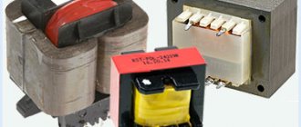
This is achieved by reducing parasitic quantities, such as interturn capacitance and inductance, by using small cores, the arrangement of turns, and reducing the number of windings. The main characteristics of the transformer are: power and operating voltage. Structurally, the device can be made in the following form:
- rod - the magnetic circuit of such a transformer is made of U-shaped plates wrapped around windings;
- armored - W-shaped plates are used, and the windings are located in coils, forming a kind of armor;
- toroidal - its appearance resembles the geometric figure of a torus, while it does not have coils, and the winding is wound on the core;
- mixed (armored rod) - assembled from four coils and a combined type magnetic circuit.
The magnetic core in the transformer is made of electrical steel plates, except for the toroidal form, in which it is made of rolled or ferromagnetic material. The coil frames are placed on insulators, and only copper wires are used. The thickness of the plates is selected depending on the frequency.
The arrangement of the windings can be made in a spiral, conical and cylindrical form. A feature of the first type is the use not of wire, but of a wide thin foil tape. Secondly, they are made with different insulation thicknesses, which affects the voltage between the primary and secondary windings. The third type is a structure with wire wound around a rod in a spiral.
FBTest v1.1 - device for testing transformers: review and testing
"FBTest v1.1", a device for detecting short-circuited turns.
Introduction.
A repairman has such a concept - intuition, a very important indicator, which in fact is simply the equivalent of the number of similar repairs carried out. Therefore, with a high degree of probability, a specialist can identify a faulty HF transformer by indirect signs, by winding resistance, by the nature of the fault, or intuitively. If there is no extensive repair experience, it can be quite difficult even for a specialist to determine a faulty HF transformer, only by replacing the piping of the transformer elements and PWM. The problem, although labor-intensive, rarely arises, so the issue of checking the RF transformer in switching power supplies did not arise until industrial switching power supplies began to be repaired.
| For reference. The cost of repairing a commercial switching power supply starts from 500 rubles. while the power supply itself costs from 250 rubles. It is quite clear why there is no point in repairing a commercial switching power supply. With industrial power supplies the situation is different, with the cost of a power supply being 4.5 tr - 20 tr. checking an HF transformer with a 100% guarantee if the power switch fails at the initial diagnostic stage becomes very important. |
The most unpleasant thing about diagnosing a faulty transformer is the fact that the conclusion about its malfunction is made after replacing the elements of the primary and secondary circuits.
A little theory.
Simplified circuit diagram for connecting the flyback power supply RF transformer
To understand the need to check the serviceability of the HF transformer, it is enough to consider the connection of the HF transformer. When the power switch fails, until the driver and current sensor fail, a significant direct current flows through the primary winding.
A failed current sensor indicates a significant current flow and strong heating of the resistors
This operating mode, although short-term, is still associated with significant heating of the primary winding; alternatively, short-circuited turns may appear due to damage to the wire insulation as a result of overheating. Accordingly, in this case, replacing only the power switch, driver, current sensor, generator will be ineffective; replacement of the HF transformer is required. Therefore, diagnosing the serviceability of an HF transformer makes diagnostics much cheaper and faster.
A little practice.
This is not to say that there is no way to test an RF transformer, in fact there are many. The most common is to connect an RF transformer to a switching power supply; if the power supply goes out of mode, the transformer has a short-circuited turn. To do this, the secondary winding of the tested HF transformer is connected to the secondary winding of the HF transformer of the working switching power supply. Attention should be paid to the fact that too long wires to the transformer being tested can disrupt the operation of the power supply if there is no fault in the transformer being tested.
Red dots mark the connection points of the SECONDARY winding of the transformer being tested
This method requires certain skill and experience, and also requires preliminary dismantling of the transformer being tested.
"FBTest v1.1", a device for detecting short-circuited turns.
It is much easier to use a ready-made/homemade device to detect short-circuited turns. Such devices operate on the principle of a sharp drop in the quality factor of the oscillatory circuit when the turns are short-circuited.
Oscillatory circuit with high (top) and low (bottom) quality factor.
If you count the number of oscillations until complete damping, you can definitely draw conclusions about the presence of short-circuited turns based on the quality factor of the coil.
| Historical reference. The method used to test transformers was still known in the Middle Ages. When making a blade, after forging, hardening and molding, blacksmiths checked the workpiece for hidden cracks before removing the bevels. The blade blank was hung on a string and hit with a metal rod; if the metal blank rang for a long time, it means there were no cracks in it. In modern conditions, crystal dishes and glass chandelier shades are checked in a similar way when selling. |
“FBTest v1.1” is a device that can be classified as a series of ready-made functional products, that is, it has a housing and is ready for use immediately after purchase. The device itself is made in a laconic style, on a body the size of a matchbox, and there are no controls at all. The task of the device is to count and display the number of pulses before attenuation; attenuation is considered to be a pulse amplitude of less than 15% of the initial one.
The dimensions of “FBTest v1.1” can be described as minimal.
The device is turned on by closing the probes, and turns off automatically. The number of counted oscillations is displayed in hexadecimal, since there are no more than 16 oscillations, a display with one familiarity is sufficient. The display itself is made on an LCD, so the device has minimal power consumption of up to 5 mA in peak mode. The LCD display is protected from damage by a transparent plastic window, so you can safely throw it into a bag with tools without fear of crushing the display. The main advantages of the device include not only its ultra-small dimensions, but also the range of the input measuring pulse of 0.5V; in practice, this means that measuring the health of the transformer can be carried out without desoldering, since the measuring pulse, in principle, will not be able to open the PN junction of the active elements.
The body of the device is opened with a fingernail, under the cover we see an ATmega48 board and an AA AA battery.
“FBTest v1.1” meter board, view from the parts side
“FBTest v1.1” meter board, view from the display side
It's not very clear in the photo, but the board has an interface for in-circuit programming, which is covered by a beeper. Despite the abundance of inscriptions, the battery terminals are not labeled; for orientation, the black probe sits on the minus of the battery, which is also the contact with the spring.
Using the device.
Since the main HF transformers found in our workshop are transformers for switching power supplies and power supplies for CCFL lamps in monitor inverters, we will only consider them. Judging by the name FBTtest, the device was originally intended to test flyback transformers (FBT), which had a tendency to fail, and at the same time have a high price tag in order to keep such spare parts for replacement. A modern commercial switching power supply has a design that ensures a high service life of the RF transformer, so the possibility of transformer output directly depends on the failure of the power switch or neck. A different picture is observed in an industrial switching power supply; exposure to aggressive environments, high humidity, sudden temperature changes make the transformer the weak point, which in turn damages the power switch. Most often, HF transformers in battery chargers and welding inverters, which are stored in garages and on balconies, are affected. In this regard, during repairs, the device is relevant when repairing industrial switching power supplies. For diagnosing commercial versions of power supplies, it is a convenient but not necessary tool; the point is not that their transformers do not often fail, but that rewinding a transformer is labor-intensive and therefore expensive. Some repair shops do not rewind transformers during repairs, and it is not always possible to buy a new one. Transformers in inverter LCD monitors have a higher probability of failure in relation to transformers in power supplies, we can’t say for sure what this is due to, but we had to wind HF transformers, a process more complicated than winding an HF transformer for a power supply.
It is much easier to check ignition transformers for CCFL lamps; for the most part, these are transformers with clearly defined windings, in which the device can only check the primary winding (from the side of the power switches), the device does not detect the secondary winding (from the side of CCFL lamps), the pulse voltage is too low . The measurement results confirm the practice.
Faulty CCFL lamp inverter transformer
The same faulty transformer, we short-circuit the winding in the break.
The same faulty transformer, we short-circuit the winding, which rings as 1280 ohms.
Serviceable CCFL lamp inverter transformer
With pulse power supply transformers, everything is somewhat more complicated, there are a large number of windings, at least one primary, one secondary (maybe more), one for PWM power supply. It makes sense to check only the primary winding, since the rest show complete nonsense, regardless of whether the transformer is soldered or desoldered. It was not possible to find a faulty transformer, so we emulate a short-circuited turn with a jumper.
Serviceable pulse power supply transformer
Faulty pulse power supply transformer
If you don’t have enough skills to determine the primary winding, check all the windings; if at least one gives a number greater than 4, then the HF transformer is working.
Unfortunately, the device cannot detect short-circuited turns on low-frequency transformers; transformers made of permalloy (a set of W-shaped thin plates) are not available for diagnostics.
Measurements that we cannot explain.
An example of a transformer that is known to be faulty, which, oddly enough, is determined to be working.
FBTest v1.1 readings, on a obviously faulty transformer
Right winding resistance
Left winding resistance
How the device works
The operating principle of IT is based on the occurrence of electromagnetic induction. So, if voltage is applied to the primary winding, then alternating current will begin to flow through it. Its appearance will lead to the emergence of a magnetic flux that is variable in magnitude. Thus, this coil is a kind of source of magnetic field. This flux is transmitted through the short-circuited core to the secondary winding, inducing an electromotive force (EMF) on it.
The magnitude of the output voltage depends on the ratio of the number of turns between the primary and secondary windings, and the maximum current depends on the cross-section of the wire used. When connecting a powerful load to the output, current consumption increases, which, with a small wire cross-section, leads to overheating of the transformer, damage to the insulation and burnout.
The operation of IT also depends on the frequency of the signal that is supplied to the primary winding. The higher this frequency is, the smaller losses will occur during energy transformation. Therefore, at a high speed of pulses supplied, the dimensions of the device can be smaller. This is achieved by operating the magnetic circuit in saturation mode, and to reduce the residual induction, a small air gap is used. This principle is used in the construction of IT, to which a signal is supplied with a duration of only a few microseconds.
Preparation and testing
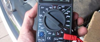
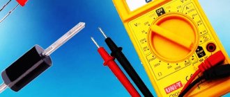
To check the operation of a pulse transformer, you can use both an analog and digital multimeter. The use of the second is preferable due to its ease of use. The essence of preparing a digital tester comes down to checking the battery and test leads. At the same time, the pointer-type device is additionally adjusted to this.
The analog device is configured by switching the operating mode to the area of measuring the minimum possible resistance. Afterwards, two wires are inserted into the tester sockets and short-circuited. Using a special construction handle, the position of the arrow is set opposite zero. If the arrow cannot be set to zero, then this indicates discharged batteries that will need to be replaced.
It's easier with a digital multimeter. Its design uses an analyzer that monitors the condition of the battery and, if its parameters deteriorate, displays a message on the tester screen indicating that it needs to be replaced.
When checking transformer parameters, two fundamentally different approaches are used. The first is to assess the serviceability directly in the circuit, and the second - autonomously from it. But it is important to understand that if the IT is not removed from the circuit, or at least a number of pins are not disconnected, then the measurement error can be very large. This is due to other radioelements that shunt the input and output of the device.
Procedure for identifying defects
An important step in checking a transformer with a multimeter is identifying the windings. However, their direction does not play a significant role. This can be done using the markings on the device. Usually a certain code is indicated on the transformer.
In some cases, a diagram of the location of the windings or even their conclusions may be marked on the IT. If the transformer is installed in the device, then a circuit diagram or specification will help in finding the pinout. Also often the designations of the windings, namely the voltage and the common terminal, are signed on the PCB itself near the connectors to which the device is connected.
Once the conclusions have been determined, you can proceed directly to testing the transformer. The list of malfunctions that may occur in the device is limited to four points:
- core damage;
- burnt out contact;
- insulation breakdown leading to an interturn or frame short circuit;
- wire break.
The verification sequence is reduced to an initial external inspection of the transformer. It is carefully checked for blackening, chips, and odor. If no obvious damage is detected, then proceed to measurement with a multimeter.
Investigation for open circuit and short circuit
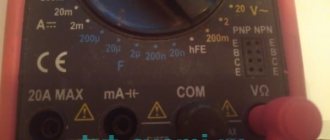
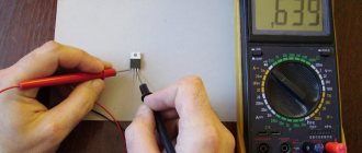
To check the integrity of the windings, it is best to use a digital tester, but you can also examine them using a pointer tester. In the first case, the diode testing mode is used, indicated on the multimeter by the symbol -|>| —))). To determine a break, test leads are connected to the digital device. One is inserted into the connectors marked V/Ω, and the second is inserted into COM. The roller switch is moved to the dialing area. The measuring probes are sequentially touched to each winding, red to one of its terminals, and black to the other. If it is intact, the multimeter will beep.
An analog tester performs the test in resistance measurement mode. To do this, the tester selects the smallest resistance measurement range. This can be implemented through buttons or a switch. The probes of the device, as in the case of a digital multimeter, touch the beginning and end of the winding. If it is damaged, the arrow will remain in place and will not deviate.
The same procedure is used to check for short circuits. A short circuit may occur due to an insulation breakdown. As a result, the winding resistance will decrease, which will lead to redistribution of the magnetic flux in the device. To carry out testing, the multimeter switches to resistance testing mode. By touching the windings with probes, they look at the result on a digital display or on a scale (arrow deflection). This result should not be less than 10 ohms.
To make sure that there is no short circuit on the magnetic circuit, touch the “hardware” of the transformer with one probe, and touch the second one sequentially to each winding. There should be no deviation of the arrow or appearance of a sound signal. It is worth noting that the interturn short circuit can only be measured with a tester in an approximate form, since the error of the device is quite high.
Voltage and current measurements
If a transformer is suspected of malfunctioning, testing can be carried out without completely disconnecting it from the circuit. This testing method is called direct, but is associated with the risk of electric shock. The essence of current measurement is to perform the following steps:
- one of the legs of the secondary winding is unsoldered from the circuit;
- the black wire is inserted into the COM socket of the multimeter, and the red wire is connected to the connector marked with the letter A;
- The device switch is moved to the position corresponding to the ACA zone.
- The probe connected to the red wire touches the free leg, and the black wire touches the place to which it was soldered.
When voltage is applied, if the transformer is operational, a current will begin to flow through it, the value of which can be seen on the tester screen. If IT has several secondary windings, then the current strength is checked on each of them.
The voltage measurement is as follows. The circuit with the transformer installed is connected to the power source, and then the tester switches to the ACV (alternating signal) region. The wire plugs are inserted into the V/Ω and COM sockets and touch the beginning and end of the winding. If the IT is normal, the result will be displayed on the screen.
Removing characteristics
To be able to check a transformer with a multimeter using this method, its current-voltage characteristic is necessary. This graph shows the relationship between the potential difference at the terminals of the secondary windings and the current strength leading to their magnetization.
The essence of the method is as follows: the transformer is removed from the circuit, and pulses of different sizes are applied to its secondary winding using a generator. The power supplied to the coil must be sufficient to saturate the magnetic circuit. Each time the pulse changes, the current in the coil and the voltage at the output of the source are measured, and the magnetic circuit is demagnetized. To do this, after removing the voltage, the current in the winding increases in several approaches, after which it decreases to zero.
As the current-voltage characteristic is taken, its real characteristic is compared with the reference one. A decrease in its slope indicates the appearance of an interturn short circuit in the transformer. It is important to note that to plot the current-voltage characteristic it is necessary to use a multimeter with an electrodynamic head (pointer).
Thus, using a regular multimeter, you can with a high degree of probability determine the performance of IT , but for this it is best to perform a set of measurements. Although, to correctly interpret the result, you should understand the operating principle of the device and imagine what processes occur in it, but in principle, for successful measurement it is enough just to be able to switch the device to different modes.
How to test a pulse transformer with a multimeter
To check the pulse transformer, you can use both an analog device and a digital multimeter. The use of the second is preferable due to its ease of use. The essence of preparing a digital tester comes down to checking the battery and test leads. At the same time, the pointer-type device is additionally adjusted to this.
Method of testing with an analogue (pointer) measuring device
- The analog device is configured by switching the operating mode to the area of measuring the minimum possible resistance.
- Afterwards, two wires are inserted into the tester sockets and short-circuited.
- Using a special construction handle, the position of the arrow is set opposite zero. If the arrow cannot be set to zero, then this indicates discharged batteries that will need to be replaced.
Procedure for identifying defects
An important step in checking a transformer with a multimeter is identifying the windings. However, their direction does not play a significant role. This can be done using the markings on the device. Usually a certain code is indicated on the transformer.
In some cases, a diagram of the location of the windings or even their conclusions may be marked on the IT. If the transformer is installed in the device, then a circuit diagram or specification will help in finding the pinout. Also often the designations of the windings, namely the voltage and the common terminal, are signed on the PCB itself near the connectors to which the device is connected.
Once the conclusions have been determined, you can proceed directly to testing the transformer. The list of malfunctions that may occur in the device is limited to four points:
- core damage;
- burnt out contact;
- insulation breakdown leading to an interturn or frame short circuit;
- wire break.
The verification sequence is reduced to an initial external inspection of the transformer. It is carefully checked for blackening, chips, and odor. If no obvious damage is detected, then proceed to measurement with a multimeter.

