The power supply circuits of many modern devices contain voltage stabilizers. Usually these are 7805, 7812 and others. They are needed in order to maintain a stable output voltage, receiving a higher one at the input.
The output voltage rating can often be determined by the markings on the housing of the radio component, for example, 7805 - 5 V, 7812 - 12 V, and 17-33 - 3.3 V. In order to test the voltage stabilizer, you need to apply a voltage of a certain nominal value to the input and measure the voltage at the exit. In this article I will check the serviceability of the L7812AB2T and 17-33G stabilizers I have.
L7815cv specifications wiring diagram
A voltage stabilizer is the most important radio element of modern radio-electronic devices. It provides a constant voltage at the output of the circuit, which is almost independent of the load.
Stabilizers of the LM family
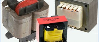
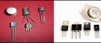
In our article we will look at voltage stabilizers of the LM78XX family. The 78XX series is produced in metal cases TO-3 (left) and in plastic cases TO-220 (right). Such stabilizers have three terminals: input, ground (common) and output.
Instead of “XX”, manufacturers indicate the stabilization voltage that this stabilizer will give us. For example, a 7805 stabilizer will produce 5 Volts at the output, 7812 will produce 12 Volts, and 7815 will produce 15 Volts. Everything is very simple.
Connection diagram
And here is the connection diagram for such stabilizers. This circuit is suitable for all stabilizers of the 78XX family.
In the diagram we see two capacitors that are sealed on each side. These are the minimum values of capacitors; it is possible, and even desirable, to supply a higher value. This is required to reduce ripple at both the input and output. For those who have forgotten what ripple is, you can look at the article on how to obtain a constant voltage from an alternating voltage.
Characteristics of LM stabilizers
What voltage should be supplied for the stabilizer to work as it should? To do this, we are looking for a datasheet for stabilizers and studying it carefully. We are interested in these characteristics:
Output voltage – output voltage
Input voltage – input voltage
We are looking for our 7805. It gives us an output voltage of 5 Volts. Manufacturers noted a voltage of 10 volts as the desired input voltage. But it happens that the output stabilized voltage is sometimes either slightly underestimated or slightly overestimated.
For electronic trinkets, fractions of volts are not felt, but for precision (accurate) equipment it is better to assemble your own circuits. Here we see that the 7805 stabilizer can give us one of the voltages in the range of 4.75 - 5.25 Volts, but the conditions must be met that the output current in the load will not exceed 1 Ampere. An unstabilized DC voltage can “fluctuate” in the range from 7.5 to 20 Volts, while the output will always be 5 Volts.
The power dissipation on the stabilizer can reach up to 15 Watts - this is a decent value for such a small radio component. Therefore, if the load at the output of such a stabilizer consumes a decent current, I think it’s worth thinking about cooling the stabilizer. To do this, it must be placed on the radiator through KPT paste. The greater the current at the output of the stabilizer, the larger the radiator should be. It would be generally ideal if the radiator was also blown by a fan.
LM work in practice
Let's look at our ward, namely the LM7805 stabilizer. As you already understand, at the output we should get 5 Volts of stabilized voltage.
We take our Breadboard and quickly assemble the connection diagram suggested above. The two yellow ones are capacitors, although it is not necessary to install them.
So, wires 1,2 - here we drive the unstabilized input DC voltage, remove 5 Volts from wires 3 and 2.
On the Power Supply we set the voltage in the range of 7.5 Volts and up to 20 Volts. In this case, I set the voltage to 8.52 Volts.
And what did we get at the output of this stabilizer? 5.04 Volts! This is the value we will get at the output of this stabilizer if we supply voltage in the range from 7.5 to 20 Volts. Works great!
Let's check one more of our stabilizers. I think you have already guessed how many volts it is.
We assemble it according to the diagram above and measure the input voltage. According to the datasheet, you can supply it with an input voltage from 14.5 to 27 Volts. We set 15 Volts with kopecks.
And here is the output voltage. Damn, some 0.3 Volts is not enough for 12 Volts. For radio equipment operating on 12 Volts this is not critical.
How to make a power supply for 5, 9.12 Volts?
How to make a simple and highly stable power supply for 5, 9 or even 12 Volts? Yes, very simple. To do this, you need to read this article and install a stabilizer on the radiator at the output! That's all! The circuit will be approximately like this for a 5 Volt power supply:
Two electrolytic capacitors to eliminate ripple and a highly stable 5 volt power supply at your service! To get a power supply for a higher voltage, we also need to get a higher voltage at the output of the transformer. Aim for the voltage on capacitor C1 to be no less than in the datasheet for the stabilizer being described.
To ensure that the voltage stabilizer does not overheat, apply the minimum voltage specified in the datasheet to the input. For example, for the 7805 stabilizer this voltage is 7.5 Volts, and for the 7812 stabilizer the desired input voltage can be considered a voltage of 14.5 Volts. This is due to the fact that the voltage difference, and therefore the power, the stabilizer will dissipate on itself.
As you remember, the power formula is P=IU, where U is voltage and I is current. Consequently, the higher the input voltage of the stabilizer, the greater the power consumed by it. And excess power is heating. As a result of heating, such a stabilizer may overheat and enter a protection state, in which further operation of the stabilizer stops or even burn out.
Bearing dimensions and characteristics
The main components of the roller bearing article number 7815 (30615) are a removable outer ring and an inner race on which the rolling element assembly is assembled. In the transport position, these parts are connected with wire; it must be removed before installation.
Diagram of a tapered roller bearing with tapered rollers
| Characteristic | Meaning |
| Angular contact roller bearing with tapered rollers | |
| Designation GOST 520-2011 (27365-87) | 6-7815 (6-7815A) |
| Designation ISO 355, DIN 720 | 30615 |
| Withstands load | angular contact |
| Outer diameter (D), mm | 135 |
| Inner diameter (d), mm | 75 |
| Outer ring width (B), mm | 45 |
| Inner ring width (C), mm | 35 |
| Overall width (T), mm | 44.25 |
| Weight, g | 2570 |
| Static load capacity, H | 320000 |
| Dynamic load capacity, H | 215000 |
| Rotation speed in grease, rpm | 2000 |
| Rotation speed in liquid lubricant, rpm | 3200 |
| Roller dimensions, mm | 12.85/14.87x33 |
| Number of rollers, pcs | 21 |
| steel grade | SHH-15 |
The dimensions of roller bearing 7815 (30615) in the working position are 75x135x44.5 mm. Weight does not exceed 2.57 kg. The delivery set includes the product itself, a cardboard box and a small manufacturer's instructions.
The calculated impact on bearing 7815 (30615) is radial and one-sided axial. Its total value in statics should not exceed 320 kN, in dynamics – 215 kN.
The rotation speed is affected by the type and characteristics of lubricants used in the unit. In oil, the maximum speed can reach 3,200 rpm. Grease significantly reduces this value.
Basic information about the bearing is located on the side faces of its cages. In addition to the mark of the factory and the country of production, there is a marking, its decoding complies with current standards. In the case of domestic product 6-7815:
- 6 – normal accuracy;
- 7 – tapered roller bearing;
- 8 – wide series;
- 15 – code designation of the internal diameter.
Attention! There are Russian roller bearings marked 2B6-7815. This is also a part of normal accuracy, but made taking into account additional requirements for waviness and deviation from roundness of surfaces.
Domestic analogue 7815
L7805-CV Linear DC Voltage Regulator
L7805-CV - for almost any radio amateur, assembling a power supply with a stabilizing output voltage on the 7805 microcircuit and similar ones from this series is not difficult at all. It is this linear input DC voltage regulator that will be discussed in this material.
The figure above shows a typical L7805 linear regulator with a positive polarity of 5v and a rated operating current of 1.5A. These microcircuits have become so famous that most of the world's companies have taken up their production. But in the picture below, the circuit is slightly improved, by increasing the capacitance of capacitors C1-C2.
As a rule, between radio engineers and electronics engineers this chip is called abbreviated, without naming the letters in front indicating the manufacturer. After all, it is already clear to everyone that this is a stabilizer, the last digit of which indicates its output voltage.
For those who have not yet encountered these electronic components in practice and know little about them, here is a short video on how to assemble the circuit for clarity:
Voltage stabilizer 5v! On the L7805CV chip
One of the important conditions is high quality components
In fact, when purchasing components, the manufacturer plays a significant role. When you purchase any electronic components, always pay attention to the brand of the part, and also ask who supplies it. Personally, I am satisfied with the products, a manufacturer of microelectronic components.
Unnamed stabilizers or from little-known companies, as a rule, always cost less than similar ones from well-known brands. But the quality of such parts is not always at the proper level; their operation is especially affected by a significant variation in the output voltage.
In practice, many times I came across L7805 microcircuits that produced an output voltage within 4.6v, instead of 5v, while others from the same series gave, on the contrary, more - 5.3v. In addition, such samples can often create a decent background and increased power consumption.
Current source circuit made on microcircuits from the L78xx series
The output current value is determined by a constant resistor R* connected in parallel with a 0.1uF capacitor, it is this resistance that in turn creates a load for the L7805 . Moreover, the stabilizer does not have grounding. Only one output of the load resistance Rн goes to ground. The operating principle of such a switching circuit obliges the L7805-CV to supply a certain amount of current to the load by regulating the output voltage.
The magnitude of the current at the output of the source L78хх
An unpleasant moment that can be observed in the circuit is the summation of the quiescent current Id with the output current. The quiescent current parameters are indicated in the documentation for the microcircuit. Basically, such stabilizers have a constant quiescent current of 8 mA. This value is the smallest current of the chip's output circuit. Therefore, if you try to create a current source whose value is less than 8mA, it will not work.
Here you can download documentation for the L78xx chip L78_DataSheet.pdf
At best, you can get output currents ranging from 8mA to 1A from the L7805. However, when operating at currents exceeding 750-850 mA, we strongly recommend installing the microcircuit on a radiator. But working at such currents is still not justified. The current indicated in the documentation is 1A - this is its maximum value. In actual conditions, the chip will most likely fail due to overheating. Therefore, the optimal output operating current should be between 20 mA and 750 mA.
Correct output current and voltage value
At the same time, the non-constant quiescent current is formed as Δ >
Optimal load resistance
At the same time, the value of the load resistance must be taken into account. Everything is simple here, that is, using Ohm's law you can calculate everything. For example:
Based on these simple calculations, we found out what the voltage should be across a load with a resistance of 100 Ohms in order to create an output current of 100 mA. According to these calculations, it turns out that the best option would be to use a 7812 or 7815 microcircuit, designed for 12v and 15v, in order to have a reserve.
Conclusion
Naturally, in such a current source circuit there are limiting points. Although it can be useful for a large number of solutions in which high accuracy does not play a special role. The absence of any complexity in the circuit makes it possible to manufacture a current source in almost any conditions, especially since it is not difficult to purchase components for it.
Bearings at wholesale prices
Do you need bearings at low prices?
Send us applications, we will offer the best prices We have:
- Your own Russian brand
- If necessary, we also supply quality without a brand.
- Fully complies with GOST
- All products have passports and certificates
We are waiting for your applications by mail:
[email protected] A typical example of a product of this class is GOST 7815. This is a bearing of a wide series, which indicates its high load-carrying capacity. This designation corresponds to domestic products; products from foreign manufacturers are marked ISO 30615.
Connection diagram for stabilizer L7805CV, description of characteristics
The L7805 CV integrated stabilizer is a conventional three-terminal 5V positive voltage regulator.
Produced by STMircoelectronics, approximate price is about $1. Made in a standard TO-220 package (see figure), in which many transistors are made, however, its purpose is completely different. In the marking of the 78XX series, the last two digits indicate the rating of the stabilized voltage, for example:
- 7805 - 5 V stabilization;
- 7812 - 12 V stabilization;
- 7815 - stabilization at 15 V, etc.
The 79 series is designed for negative output voltage.
Used to stabilize voltage in various low-voltage circuits. It is very convenient to use when it is necessary to ensure the accuracy of the supplied voltage; there is no need to install complex stabilization circuits, and all this can be replaced with one microcircuit and a couple of capacitors.
Diameter and number of rollers
The inner race of roller bearing 7815 (30615) has the shape of a cone, along the side surface of which a groove is machined. It contains 21 rollers. The dimensions of each of them are 12.85/14.87x33.11 mm.
The roller cage can be made of different materials. The most commonly used is carbon steel. Such products are distinguished by their low price and good performance characteristics. There are analogues in which this element is brass or cast from reinforced polyamide.
Connection diagram L7805CV
The connection diagram for the L 7805 CV is quite simple; to operate it is necessary, according to the datasheet, to place capacitors at the input of 0.33 μF and at the output of 0.1 μF.
It is important during installation or design to place the capacitors as close as possible to the terminals of the microcircuit. This is done to ensure the maximum level of stabilization and reduce interference. According to the characteristics, the L7805CV stabilizer is operational when supplying an input DC voltage ranging from 7.5 to 25 V. The output of the microcircuit will be a stable DC voltage of 5 Volts. This is the beauty of the L7805CV chip.
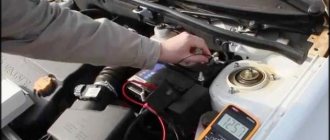
Checking the functionality of the L7805CV
How to check the functionality of the microcircuit?
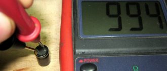
To begin with, you can simply ring the terminals with a multimeter; if in at least one case a short is observed, then this clearly indicates a malfunction of the element. If you have a power source of 7 V or higher, you can assemble a circuit according to the datasheet given above and apply power to the input; at the output, use a multimeter to record the voltage at 5 V, so the element is absolutely operational. The third method is more labor-intensive if you do not have a power source. However, in this case, you will also receive a 5 V power supply in parallel. It is necessary to assemble a circuit with a rectifier bridge according to the figure presented below. To check, you need a step-down transformer with a transformation ratio of 18 - 20 and a rectifier bridge, a further standard kit, two capacitors for the stabilizer and that’s it, the 5 V power supply is ready. The capacitor values here are overestimated in relation to the L7805 connection diagram in the datasheet, this is due to the fact that it is better to smooth out voltage ripples after the rectifier bridge. For safer operation, it is advisable to add an indication to visualize the device being turned on. Then the diagram will look like this:
If there are a lot of capacitors or any other capacitive load on the load, you can protect the stabilizer with a reverse diode to prevent the element from burning out when the capacitors are discharged.
The big advantage of the microcircuit is its fairly lightweight design and ease of use, if you need power of one value. Circuits sensitive to voltage values must be equipped with such stabilizers to protect elements sensitive to voltage surges.
Analogs and modifications
If the imported bearing 30615 is produced in one version, but with different types of cages, then its domestic analogue is offered in two modifications. The basic type product does not have additional options. notation. The marking of the reinforced version is 7815A.
| Modification | Add. Marking |
| Pressed cage made of non-hardened steel | J, J1, J2 |
| the same as without A | A (GOST) |
| Polyamide separator | TVH, TV, TN9 and TNG |
| With improved internal geometry and super-finish surface treatment | Q |
| Dimensions fully comply with ISO standard | X |
| Accuracy class (default 6 or P6). The lower the number, the more accurate and more expensive it is. | 4-, 5-, 6- (GOST) and P4, P5, P6 (ISO) |
Both Russian modifications are interchangeable, they have identical dimensions and weight. At the same time, the reinforced bearing has a high load-carrying capacity and therefore will last longer.
Characteristics of the L7805CV stabilizer, its analogues
Main parameters of the L7805CV stabilizer:
- Input voltage - from 7 to 25 V;
- Power dissipation - 15 W;
- Output voltage - 4.75...5.25 V;
- Output current - up to 1.5 A.
The characteristics of the microcircuit are given in the table below; these values are valid provided that certain conditions are met.
Namely, the temperature of the microcircuit is in the range from 0 to 125 degrees Celsius, the input voltage is 10 V, the output current is 500 mA (unless otherwise specified in the conditions, the Test conditions column), and the standard body kit with capacitors at the input is 0.33 μF and at the output 0 ,1 µF. The table shows that the stabilizer behaves perfectly when powered at the input from 7 to 20 V and the output will stably output from 4.75 to 5.25 V. On the other hand, supplying higher values leads to a more significant spread of output values , therefore, above 25 V is not recommended, and a decrease in input less than 7 V will generally lead to a lack of voltage at the output of the stabilizer.
When operating at heavy loads , more than 5 W, it is necessary to install a radiator on the chip to avoid overheating of the stabilizer; the design allows this to be done without any questions. Naturally, such a stabilizer is not suitable for more precise (precision) equipment, because has a significant spread in the rated voltage when the input voltage changes.
Since the stabilizer is linear, it makes no sense to use it in powerful circuits; stabilization based on pulse-width modeling will be required, but for powering small devices such as phones, children's toys, radio tape recorders and other gadgets. The domestic analogue is KR142EN5A or in common parlance “KRENKA”. In terms of cost, the analogue is also in the same category.
Applicability
Tapered roller bearings 7815 (30615) are used in the equipment of mining and processing plants, but are more often found in components of heavy vehicles.
Foreign analogue 30615
First of all, this is a hub part for domestic trucks. These roller bearings work in wheel units of almost all models of KamAZ, ZIL and PAZ buses.