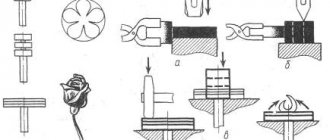
Laboratory autotransformer - LATR is one of the types of voltage regulators. Along with this device is RNO - a single-phase voltage regulator, used in single-phase networks, and RNT - a three-phase voltage regulator, designed to work with three-phase networks. These devices are structurally similar to a laboratory transformer, but differ from it in higher power. LATR itself is used for carrying out various tests, as well as measurements at sites and in laboratory conditions.
Operating principle of an autotransformer
And now, for a better understanding of the basic operating principle of autotransformers, let’s consider the processes that occur in them.
As an example, we will take an autotransformer, which can either increase the output voltage or decrease it relative to the initial one. For ease of calculation, the total number of turns of copper wire is 20; it looks like this:
As you can see, this model already has four connection points to the common winding: A1, a2, a3 and X.
A source of alternating electric current is connected to contacts A1 and N, for example, the power supply from a standard city electrical network, with voltage (U1), in our case it is standard 220V. There are a total of 18 turns of copper wire between these points; this section of the spiral is designated as W1; it is considered the primary winding of the autotransformer.
Operating principle of an autotransformer
Despite the structural features of the winding part of the unit, its operating principle is very similar to the operation of a conventional transformer. By the same principle, during the circulation of alternating current, a magnetic flux occurs in the core. Its effect on the winding is characterized by the appearance of an equal electromotive force on each individual turn. The total EMF on a section of the winding is equal to the sum of the current values of all individual turns.
A special feature is that a primary current also circulates through the winding, which is in antiphase to the induction flow. The resulting values of these currents in the section of the winding intended for the consumer are less (for a step-down winding) than the parameters of the incoming electricity.
Step-down autotransformer circuit
The ratio of the EMF values is expressed by the formula: E1/E2 = w1/w2 = k, where E is the EMF, w is the number of turns, k is the transformation ratio.
Considering that the voltage drop in the transformer windings is small, it can be ignored. In this case, the equalities are: U1 = E1; U2 = E2 can be considered fair. Thus, the above formula takes the form: U1/U2 = w1/w2 = k, that is, the ratio of voltage to the number of turns is the same as for a conventional transformer.
Without going into details, we note that the ratio of the upper coil current to the load current, as for a conventional transformer, is expressed by the formula: I1/I2 = w2/w1 = 1/k. It follows that since in a step-down transformer w2 < w1, then I2 < I1. In other words, the output current is significantly less than the input current. Thus, less energy is spent heating the wire, which allows the use of wires of smaller cross-section.
It is noteworthy that the load power is formed by currents of electromagnetic induction and the electrical component. Electrical power (P = U2*I1) is quite noticeable in comparison with the induction component entering the secondary circuit. Therefore, in order to obtain the required power, smaller cross-sections for magnetic cores are used.
Types of autotransformers
Single-phase - can only be used to connect to a single-phase 220 V network. The output voltage adjustment range is from 0 to 300 V.
Three-phase - designed for a 380 V network. They can regulate the output voltage from 0 to 430 V.
Show more ArticlesVideo 02/10/2017 LATR: what is a laboratory autotransformer for? In our country, two types of electrical networks are common - single-phase (with a voltage of 220 V) and three-phase (with a voltage of 380 V). Consequently, most electrical appliances, machinery and equipment are designed to work with such parameters. But they are not suitable for electronics and household appliances imported from the USA or Japan, because in these countries household electrical networks have a voltage of 110 V. What to do, for example, when repairing automotive electronic equipment requires a supply voltage of 12-13 V ? To adjust the voltage there are special devices - transformers. Review: Autotransformer Resanta LATR TDGC2-0.5 Autotransformers LATR Review of laboratory autotransformers SUNTEK
It will be interesting➡ Capacitor charge
Types of LATRs
Single-phase
This type of LATR produces single-phase alternating regulated voltage. It is very often used by radio amateurs, as it allows you to select any low-voltage alternating voltage.
Three-phase
This type of LATR is used in industrial electronics. A three-phase voltage is supplied to its input, and at the output we get the same three phases, but with a smaller amplitude. This LATR allows you to change the voltage amplitude of all three phases simultaneously . Roughly speaking, these are three single-phase LATRs, which are located in the same housing and which change the voltage equally.
Design and operating principle
An autotransformer is used to adjust line voltages to either change the value or keep it constant. If the adjustment is made by a small amount, then the transformation ratio is also small, and the currents in the primary and secondary windings are almost the same. Therefore, the part of the winding that causes the difference between the two currents can be made of a much smaller conductor.
The control range, leakage inductance value and overall size (due to the fact that there is no second winding) of the autotransformer with the required amount of reactive or active power is less than that of transformers that have a double winding.
Both windings - primary and secondary - are connected to each other both electrically and magnetically, and also have a common magnetic circuit. Part of the primary winding is connected to the AC power supply. Thus, by simply reversing the connections, supply voltages can be easily increased or decreased.
When the original current flows through one winding in one direction, the current in the secondary winding moves in the opposite direction. The autotransformer has several potential tapping points along the winding.
Design of a single-phase autotransformer
About the principle of operation of devices
An adjustable laboratory autotransformer, abbreviated LATR, is a device based on a magnetic core with a copper winding, where an electrical connection occurs. A carbon brush moves along the winding, thereby creating contact with the connected electrical consumer. Depending on the position of the brush, the transformation ratio changes, which, in turn, affects the value of the output voltage. Thanks to the rotary regulator, which changes the position of the brush, you can adjust the value of the current voltage supplied to the load on a scale.
Electrical consumers are connected to the laboratory autotransformer through the output terminals, in turn, the device itself is connected to the central electrical network either through the input terminals or by connecting the electrical plug to the socket.
The main difference between laboratory autotransformers and conventional ones is that the movable contact in the winding allows you to change the number of turns connected to the circuit and thereby makes it possible to set the voltage in a wide range, for example, in a single-phase network - from 0 to 250 V, in a three-phase network - from 0 up to 430 V. The number of turns changes smoothly, so it is possible to obtain the most accurate voltage values and a pure sine wave at the output. In addition, this device is lighter and more compact than analogues made according to the traditional design, and has a much higher efficiency (up to 98%). To monitor operation, there is a voltmeter on the control panel, and ventilation grilles in the case promote natural cooling of the device and prevent overheating.
LATR scheme
As mentioned above, all LATRs are classified as autotransformers and have insignificant power. At the same time, they do not require registration as a measuring instrument in the State Register of SI and, accordingly, they do not need to be verified (by metrological examination).
LATR is used on both single-phase (230/50V) and three-phase (380/50V) AC networks and consists of the following components:
- Toroidal steel core.
- Winding, which is made in the form of a single circuit (primary).
Moreover, its certain number of turns often also acts as a secondary winding and can be adjusted depending on the required U output. In order to reduce or increase the number of turns of the secondary winding, the LATR is equipped with a manual control (handle), the rotation of which causes the carbon brush to slide and move from one turn to another. Thus, the transformation ratio changes, which causes a different output U.
Important selection options
First of all, you need to determine what the autotransformer will be used for. For example, to test the performance of power equipment at a factory, you will need one model; to provide power supply when repairing car radios, you will need a completely different one. To make it easier to formulate requirements for the device, consider the following parameters:
Power. You can select an LATR with a power from 0.45 to 10 W (and even more), but first you need to calculate the load of all connected electrical consumers. Their total power should not exceed the power of the autotransformer.
Voltage adjustment range. It depends on how the device operates - to lower or increase voltage parameters. Most models are of the step-down type, especially single-phase; their operating range can be from 0 to 250 V or from 160 to 220 V. Depending on what voltage value is needed to operate the equipment, choose an LATR with the appropriate range. Three-phase models have a wider range: the lower limit can be at a level of 200-220 V. A laboratory autotransformer with a wide operating range is not always needed, for example, if the voltage in the network drops to 180 V (not higher or lower), then you can buy transformer with adjustment within 180-220 V.
Supply voltage. If you plan to connect the device to a single-phase network, then you need to buy a 220 V model, if to a three-phase network - 380 V (in this case, the adjustment range for such a model can go far beyond the nominal values of a three-phase network, for example, it can be from 0 to 430 IN).
So, have you already decided to buy a laboratory autotransformer? With this device, you yourself can adjust the voltage in the network and set the values that are necessary for a specific type of energy consumer. You can quickly select and order suitable equipment on our website. Don't delay your purchase - take control of your stress!
Operating modes
- In autotransformer modes (a), it is possible to transfer rated power from the HV winding to the LV winding or vice versa. In both modes, the series and common windings are loaded with typical power, which is acceptable.
- In transformer modes, it is possible to transfer power from the LV winding to the MV or HV winding, and the LV winding can be loaded to no more than Stype. In these modes, the AT is underloaded, which is acceptable, but uneconomical.
- In combined mode (b), it is possible to transfer power of no more than S type from the LV network to the HV network and at the same time (Snom Stype) by autotransformer from the MV network to the HV network. This mode is acceptable and economical, because the load of the common winding can, in the limit, be equal to 0, and through the AT the total is transmitted Snom.
Choosing the optimal operating mode is important for three-phase devices. They are used for continuous parameter adjustment with low losses. This component provides users with the best possible adjustment accuracy with minimal losses and therefore reduced heat generation. For three-phase current, this effect is achieved using mechanical connections of three control transformers. The sliding current collectors are designed in such a way as to ensure reliable output contact and, when triggered, simultaneous cleaning of the contact track. Carbon brushes are used that can rotate or move back and forth.
A variable autotransformer has multiple primary windings to create a secondary voltage that is regulated in the range of a few volts to fractions of volts per revolution. This is achieved by placing a carbon brush or slider in contact with one or more turns of the primary winding. Since the turns of the primary coil are evenly distributed along its length, the output value is proportional to the angular rotation of the brush.
What is an autotransformer?
From a school physics course we know that the simplest transformer consists of two coils wound on iron cores.
The magnetic field of alternating current, powered through the terminals of the primary windings, excites electromagnetic oscillations in the second coil, with a similar frequency. When a load is connected to the terminals of the working winding, it forms a secondary circuit in which an electric current arises. In this case, the voltage in the formed electrical circuit is directly proportional to the number of turns of the windings. That is: U1/U2 = w1/w2, where U1, U2 are voltages, and w1, w2 are the number of full turns in the corresponding coils.
Figure 1. Diagram of a conventional transformer and autotransformer
The autotransformer is designed a little differently. It essentially consists of one winding, from which one or more taps are made, forming secondary turns. In this case, all windings form not only an electrical, but also a magnetic connection with each other. Therefore, when electrical energy is supplied to the input of the autotransformer, a magnetic flux arises, under the influence of which an emf is induced in the load winding. The magnitude of the electromotive force is directly proportional to the number of turns forming the load winding from which the voltage is removed.
Thus, the formula given above is also valid for an autotransformer.
A large number of leads can be drawn from the main winding, which allows you to create combinations for removing voltages of different magnitudes. This is very convenient in practice, since voltage reduction is often required to power several units of electrical appliances using different voltages.
The difference between an autotransformer and a conventional transformer
As can be seen from the description of the autotransformer, its main difference from a conventional transformer is the absence of a second coil with a core. The role of secondary windings is performed by separate groups of turns having a galvanic connection. These groups do not require separate electrical insulation.
This device has certain advantages:
- the consumption of non-ferrous metals used for the manufacture of such equipment has been reduced;
- energy transfer is carried out by the influence of the electromagnetic field of the input current, and thanks to the electrical connection between the windings. Consequently, energy loss is lower, which is why autotransformers have higher efficiencies;
- light weight and compact dimensions.
Despite the design differences, the operating principle of these two types of products remains unchanged. The choice of transformer type depends, first of all, on the goals and tasks that have to be solved in electrical engineering.
Types of autotransformers
Depending on which networks (single-phase or three-phase) the voltage needs to be changed, the appropriate type of autotransformer is used. They are single-phase or three-phase. To transform current from three phases, you can install three autotransformers designed for operation in single-phase networks, connecting their terminals with a triangle or an asterisk.
Transformer winding connection diagram
There are types of laboratory autotransformers that allow you to smoothly change the output voltage values. This effect is achieved by moving a slider along the surface of the open part of a single-layer winding, similar to the operating principle of a rheostat. Turns of wire are applied around a ring-shaped ferromagnetic core, along the circumference of which the contact slider moves.
Autotransformers of this type were widely used throughout the USSR during the era of mass distribution of tube televisions. At that time, the network voltage was unstable, which caused image distortion. Users of this imperfect technology had to adjust the voltage to 220 V from time to time.
Before the advent of voltage stabilizers, the only way to achieve optimal power parameters for household appliances of that time was the use of LATR. This type of autotransformer is still used today in various laboratories and educational institutions. With their help, electrical equipment is adjusted, highly sensitive equipment is tested, and other tasks are performed.
In special equipment where the loads are insignificant, DATR autotransformer models are used.
Autotransformer LATR
There are also autotransformers:
- low power, for operation in circuits up to 1 kV;
- medium-power units (more than 1 kV);
- high-voltage autotransformers.
It should be noted that for safety reasons, the use of autotransformers as power transformers to reduce voltages exceeding 6 kV to 380 V is limited. This is due to the presence of a galvanic connection between the windings, which is not safe for the end user. In case of accidents, it is possible that high voltage will reach the powered equipment, which is fraught with unpredictable consequences. This is the main disadvantage of autotransformers.
Designation on diagrams
It is very easy to distinguish the autotransformer in the diagram from the image of a conventional transformer. A sign is the presence of a single winding connected to one core, indicated by a thick line in the diagrams. Windings are shown schematically on one or both sides of this line, but in an autotransformer they are all connected to each other. If the turns are shown autonomously in the diagram, then we are talking about a regular transformer.
Safety precautions when working with LATR
I would also like to add a few words about safety precautions. There are LATRs with non-galvanic isolation. This means that the phase wire from the network goes directly to the output of such a LATR. The LATR circuit without galvanic isolation looks like this:
In this case, a network voltage of 220 Volts may appear at the output terminal of the LATR with a probability of 50/50. It all depends on how you plug the LATR mains plug into a 220 Volt socket.
If you look closely at the circuit diagram on the front panel of the LATR Resanta, you can see that the “X” and “x” terminals (the two bottom ones) are connected to each other by a conductor.
That is, if there is a phase on the “X” terminal, then there will also be a phase on the “x” terminal! You won’t measure the phase in the socket every time to insert the plug correctly, will you? Therefore, BE extremely CAREFUL! Try not to touch the LATR output terminals with your bare hands!
In principle, I touched it and nothing like that happened to me. The problem turned out to be that I have a wooden floor, which is almost a dielectric. I measured the voltage between me and the phase - about 40 Volts came out. That's why I didn't feel these 40 Volts. If I grabbed the battery with one hand or stood with my bare feet on the ground, and with the other hand grabbed the output “x” of the LATR, then I would be shaken very, very hard, since all the full 220 Volts would pass through me.
How LATR works in practice
Let's conduct experiments with a 95 Watt 220 Volt incandescent light bulb. To do this, connect it to the output terminals on the right.
I wonder at what voltage the light bulb filament will start to glow? Let's find out! We turn the regulator until we notice a faint glow of the light bulb.
We look at the regulator scale. 35 Volts!
Did you know that in the USA the mains voltage is 110 Volts? I wonder how our light bulb would glow then? We set it to 110 Volts.
It glows, as they say, at full incandescence.
Now compare how it glows at 220 V
There is no point in increasing the voltage further. The light bulb may burn out.
If you want to set the voltage with great accuracy, then, of course, you can’t do without a multimeter. To do this, set the multimeter knob to the AC voltage measuring position.
We cling and measure the alternating voltage. At the same time, we adjust it using the LATR regulator. Exactly 110 Volts!
Isolation transformer and LATR
There are also safer types of LATRs. They include an isolating transformer. The diagram of such a LATR looks something like this:
As we can see, the phase wire is isolated from the output terminals of such a LATR, thanks to a transformer, the operating principle of which you can read in this article. In this case, we may be shaken if we set a high voltage at the output of the LATR using a twister and grab two output wires of the LATR at once. That is, there is a typical galvanic isolation here.
It will be interesting➡ Useful power
Description of the work of LATRA RESANTA
Let's look at a single-phase LATR manufactured in Latvia RESANTA (read in Russian) brand TDGC2-0.5 kVA.
From above our LATR looks like this:
We see a regulator with which we can set the voltage we need.
On the front side we see some kind of alternating voltage voltmeter. We apply voltage from the 220 V network to the terminals on the left, and from the terminals on the right - the voltage that we currently require.
Main pros and cons
Due to its design features, the autotransformer has advantages and disadvantages compared to conventional devices.
Advantages of an autotransformer, manifested at Ktr0.5-2:
- less weight and dimensions;
- higher efficiency associated with reduced losses in the windings and magnetic core.
In addition to advantages, these devices have disadvantages:
- Increased short-circuit current. This is due to the fact that the load current is limited not by the saturation of the magnetic circuit, but by the resistance of several turns of the secondary winding.
- Electrical connection between the primary and secondary windings. This makes it impossible to use these devices as separation devices and for powering low-voltage devices in hazardous conditions that require low voltage according to the Electrical Regulations.
Advantages and disadvantages
To the advantages described above, we can add the low cost of products, due to the reduction in the cost of non-ferrous metals used and the cost of transformer steel. Autotransformers are characterized by insignificant energy losses of currents circulating through the windings and cores, which makes it possible to achieve efficiency levels of up to 99%.
To the disadvantages should be added the need for solid neutral grounding equipment. Due to the existing probability of a short circuit and the possibility of transmitting high voltage through the network, there are certain restrictions on the use of autotransformers.
Due to the galvanic connection of the windings, there is a danger of atmospheric overvoltages passing between them. However, despite their disadvantages, autotransformers still find wide application in a wide variety of fields.
Homemade device
Normal battery voltage when disconnected from the vehicle is between 12.5 V and 15 V. Therefore, the charger must produce the same voltage. The charge current should be approximately 0.1 of the capacity, it can be less, but this will increase the charging time. For a standard battery with a capacity of 70-80 Ah, the current should be 5-10 amperes, depending on the specific battery. Our homemade battery charger must meet these parameters. To assemble a charger for a car battery, we need the following elements:
Transformer. Any old electrical appliance or one purchased on the market with an overall power of about 150 watts is suitable for us, more is possible, but not less, otherwise it will get very hot and may fail. It’s great if the voltage of its output windings is 12.5-15 V and the current is about 5-10 amperes. You can view these parameters in the documentation for your part. If the required secondary winding is not available, then it will be necessary to rewind the transformer to a different output voltage. For this:
- Remove all unnecessary secondary windings, leaving only the primary.
- Calculate the required number of turns and wire cross-section for the appropriate voltage and current. For this there are special calculators and formulas from the physics course. The required wire diameter is calculated according to the table below. The wire must be in varnish insulation. And the number of turns is determined by the ratio: U1/U2=N1/N2. It follows that if your primary winding consists of 480 turns, then to obtain 13 Volts at the output you need to wind only 26 turns, since the network voltage is 220 Volts.
- After this, lay the wire on the base, turn to turn, insulating between the layers with paper or electrical tape in several layers. Bring out the end and beginning of the windings and securely fasten them to the body. To solder wires to them, strip the insulation with a knife.
- To reduce noise and vibration, as well as improve insulation, you can impregnate the device with paraffin.
Thus, we found or assembled the ideal transformer to make our own battery charger.
We will also need:
- 4 diodes. Any diodes with a current of at least 10 amperes will do. Some of the most popular: imported - 10A10, domestic - D242A, 2D203A, KD213B. Or diode bridges, for example: KVRS1001, KVRS1002 and their analogues.
- 4 radiators for diodes. You can, of course, do without them at low currents of the order of 3-5 Amperes. But this can lead to their rapid failure, so radiators with an area of 32 square meters are required. cm or 128 sq. cm for diode bridge. They can be made from sheet aluminum or use coolers from computers and motherboards.
- Demountable electrical plug or power cord.
- Copper wires with a cross-section of at least 2.5 square meters. mm.
- Fuses for 0.5A and 10A.
- Heat shrink tubing or electrical tape.
- A dielectric plate, or even better, a casing, such as plywood or plastic.
- A piece of nichrome wire from an electric stove.
- Multimeter or voltmeter with ammeter.
- Soldering iron, solder and flux (rosin or LTI-120).
- A few more radio components if we want to make a device with protection and automatic shutdown.
Having prepared all the materials, you can proceed to the process of assembling the car charger itself.
To make a charger for a car battery with your own hands, you need to follow the step-by-step instructions:
- We create a homemade battery charging circuit. In our case it will look like this:
- We use transformer TS-180-2. It has several primary and secondary windings. To work with it, you need to connect two primary and two secondary windings in series to obtain the desired voltage and current at the output.
- Using a copper wire we connect pins 9 and 9'.
- On a fiberglass plate we assemble a diode bridge from diodes and radiators (as shown in the photo).
- We connect pins 10 and 10' to the diode bridge.
- We install a jumper between pins 1 and 1'.
- Using a soldering iron, attach a power cord with a plug to pins 2 and 2'.
- We connect a 0.5 A fuse to the primary circuit, and a 10-amp fuse to the secondary circuit, respectively.
- We connect an ammeter and a piece of nichrome wire into the gap between the diode bridge and the battery. One end of which is fixed, and the other must provide a moving contact, thus the resistance will change and the current supplied to the battery will be limited.
- We insulate all connections with heat shrink or electrical tape and place the device in the housing. This is necessary to avoid electric shock.
- We install a moving contact at the end of the wire so that its length and, accordingly, the resistance are maximum. And connect the battery. By decreasing or increasing the length of the wire, you need to set the desired current value for your battery (0.1 of its capacity).
- During the charging process, the current supplied to the battery will itself decrease and when it reaches 1 ampere, we can say that the battery is charged. It is also advisable to directly monitor the voltage on the battery, but to do this it must be disconnected from the charger, since when charging it will be slightly higher than the actual values.
It will be interesting➡ Voltage control relay
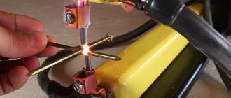
The first start-up of the assembled circuit of any power source or charger is always carried out through an incandescent lamp, if it lights up at full intensity - either there is an error somewhere, or the primary winding is short-circuited! An incandescent lamp is installed in the gap of the phase or neutral wire feeding the primary winding.
This circuit of a homemade battery charger has one big drawback - it does not know how to independently disconnect the battery from charging after reaching the required voltage. Therefore, you will have to constantly monitor the readings of the voltmeter and ammeter. There is a design that does not have this drawback, but its assembly will require additional parts and more effort.
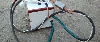
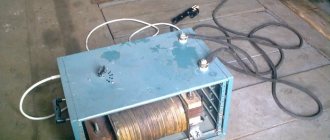
A visual example of the finished product
Peculiarities
Considering what LATR is, it should be noted that this is a type of autotransformer. It is characterized by low power and does not require a state register. The operating principle of a laboratory regulating autotransformer is to adjust the AC voltage of a single-phase (on the left in the photo) or three-phase network (on the right).
The LATR circuit includes a toroidal steel core. There is only one contour on it. This device does not have two separate windings. The contours are combined. One part can be classified as coils of the primary type, and the other - as coils of the secondary type. The LATR regulating autotransformer has a fairly simple circuit. The user can independently adjust the number of turns of the secondary winding. This distinguishes the presented type of units from other transformers. We wrote about how to assemble an LATR with your own hands here.
Device and design features
As noted above, an autotransformer consists of a single coil. It is wound on a regular or toroidal core.
Toroidal transformer
Due to its design features, it does not have galvanic isolation between the circuits, which can lead to high-voltage shock. Therefore, the step-down autotransformer, due to its increased danger, requires additional measures to protect against electric shock. Working with it is permitted subject to strict adherence to safety rules.
Necessary parameters when choosing LATR
The strength of the current passing through the windings of the autotransformer depends on two quantities: load power and output voltage.
That is, connecting this or that equipment (load) with different power consumption and adjusting the voltage at the output of the LATR using a rotary knob changes the current value. This means that in order not to exceed the maximum permissible current of the LATR, all manipulations with the device must be done consciously, understanding the meaning of each value and constantly monitoring the current according to the formula.
The main criterion for choosing a LATR model is the current that will pass through it. The passport indicates the maximum current for each model of voltage stabilizer. For example, model SUNTEK 5000, maximum current - 20 Amperes. That is, if the consumer will be used at a voltage of 250 Volts, then we multiply 250 by 20 and get the permitted power, 5000 Watts. But! If you want to use LATR at 100 Volts, the maximum current remains the same, 20 Amps and then the maximum power will be 100 times 20 for a total of 2000 Watts. This law must always be used so that LATR works for a long time and flawlessly.
What is a laboratory autotransformer (LATR)
Very often among electricians and electronics engineers the abbreviation LATR . Remember, we once looked at the power supply and even made it ourselves. The power supply gave us a constant voltage from zero to some final value, which, of course, depended on the steepness of the power supply. Agree, a very convenient thing. But there is one drawback - it only gives us constant voltage .
But, since there is a power supply for constant voltage, then there must be a power supply for alternating voltage . And such a power supply is called a laboratory autotransformer , or LATR . What is this thing and what is it eaten with?
LATR is the same transformer. It converts alternating voltage of one magnitude into alternating voltage of another magnitude . But the trick is that we can change the voltage at the LATR output if necessary.
Operating rules
The disadvantage of a homemade charger for a 12V battery is that after the battery is fully charged, the device does not automatically turn off. That is why you will have to periodically glance at the scoreboard in order to turn it off in time. Another important nuance is that checking the charger for spark is strictly prohibited.
Additional precautions to take include:
- when connecting the terminals, make sure not to confuse “+” and “-”, otherwise a simple homemade battery charger will fail;
- connection to the terminals should only be made in the off position;
- the multimeter must have a measurement scale greater than 10 A;
- When charging, you should unscrew the plugs on the battery to avoid its explosion due to boiling of the electrolyte.
Master class on creating a more complex model
That, in fact, is all I wanted to tell you about how to properly make a charger for a car battery with your own hands. We hope that the instructions were clear and useful for you, because... This option is one of the simplest types of homemade battery charging!
Also read:
- How to assemble a distribution board
- Connection diagram of a single-phase electric meter to the network
- Why does the RCD trip?
A visual example of the finished product
Master class on creating a more complex model
Application area
The features of the autotransformer allow it to be used in everyday life and various areas of industry.
Metallurgical production
Regulated autotransformers in metallurgy are used to check and adjust the protective equipment of rolling mills and transformer substations.
Utilities
Before the advent of automatic stabilizers, these devices were used to ensure the normal operation of televisions and other equipment. They consisted of a winding with a large number of taps and a switch. He switched the output of the coil, and the output voltage was controlled using a voltmeter.
Currently, autotransformers are used in relay voltage stabilizers.
Reference! In three-phase stabilizers, three single-phase autotransformers are installed, and adjustment is made in each phase separately.
Chemical and petroleum industry
In the chemical and petroleum industries, these devices are used to stabilize and regulate chemical reactions.
Production of equipment
In mechanical engineering, such devices are used to start electric motors of machine tools and control the rotation speed of additional drives.
Educational establishments
In schools, technical schools and institutes, LATRs are used to perform laboratory work and demonstrate the laws of electrical engineering, and experiments on electrolysis.