Information about the manufacturer of the vertical drilling machine 2A125
Manufacturer of vertical drilling machines models 2A125 , 2A135, 2A150, 2G175 - Sterlitamak Machine Tool Plant , founded in 1941.
The history of the Sterlitamak Machine Tool Plant begins on July 3, 1941, when the evacuation of the Odessa Machine Tool Plant to the city of Sterlitamak began.
Already on October 11, 1941, the Sterlitamak Machine Tool Plant began producing special modular machines for the defense industry.
Currently, the plant produces metalworking equipment, including CNC lathes and milling machines, multifunctional machining centers.
Products of the Sterlitamak Machine Tool Plant
- 2135
— universal vertical drilling machine, Ø 35 - 2A125
- universal vertical drilling machine, Ø 25 - 2A135
- universal vertical drilling machine, Ø 35 - 2A150
- universal vertical drilling machine, Ø 50 - 2G175
- universal vertical drilling machine, Ø 75 - 2N125
- universal vertical drilling machine, Ø 25 - 2N135
- universal vertical drilling machine, Ø 35 - 2N150
- universal vertical drilling machine, Ø 50 - 2R135F2
- CNC vertical drilling machine, Ø 35 - 2С50
- universal vertical drilling machine, Ø 50 - 2S125, 2S125-1 (2S125-01), 2S125-04
- universal vertical drilling machine, Ø 25 - 2S132, 2S132K
- universal vertical drilling machine, Ø 32 - 2С150ПМФ4
- vertical drilling-milling-boring machine with CNC and ASI, 500 x 1000 - 2С550А
– radial drilling machine, Ø 36 - 400V
- vertical drilling-milling-boring machine with CNC and ASI, 400 x 900 - 500V (STC F55)
- vertical milling center, 630 x 1200 - SF-16, SF-16-02, SF-16-05
- tabletop milling and drilling machine, Ø 16
2A150 universal vertical drilling machine. Passport, diagrams, characteristics, description
The manufacturer of drilling machines models 2A125, 2A135, 2A150, 2G175 is Sterlitamak Machine Tool Plant, LLC NPO Stankostroyeniye, founded in 1941.
The history of the Sterlitamak Machine Tool Plant begins on July 3, 1941, when the evacuation of the Odessa Machine Tool Plant to the city of Sterlitamak began.
Already on October 11, 1941, the Sterlitamak Machine Tool Plant began producing special modular machines for the defense industry.
Currently, the plant produces metalworking equipment, including CNC lathes and milling machines, multifunctional machining centers, metalworking and cutting tools.
Products of the Sterlitamak Machine Tool Plant
Universal vertical drilling machines 2A150 with a nominal drilling diameter of 35, 50 mm, respectively, are used in enterprises with single and small-scale production and are designed to perform the following operations: drilling, reaming, countersinking, countersinking, reaming and trimming ends with knives.
The limits of spindle speeds and feeds make it possible to process various types of holes using rational cutting conditions.
The universal vertical drilling machine, model 2A150, is designed for work in repair and tool shops, as well as in production shops with small-scale production; a machine equipped with accessories can be used in mass production.
Chronology of the plant's production of vertical drilling machines of the 2150 series with drilling diameters up to 50 mm:
- 2150 - the first model of a series of vertical drilling machines, produced from 1945 to 1950.
- 2A150 - the next models in the series, produced from 1950 to 1965.
- 2N150 - the most popular and widespread model of the series, produced from 1965 to the early 90s
- 2S150 - the latest models in the series. Discontinued in 2014
The presence on the machine of a nine-speed gearbox with a control range of 68-100-140-195-175-400-530-750-1100 rpm, an 11-speed feed box with a control range of 0.115 to 1.6 mm per revolution and electric reverse provides selection of standard cutting modes for hole diameters up to 35 mm when drilling, reaming, countersinking, countersinking, reaming, threading, and also allows the use of cutting tools equipped with carbide.
The presence of mechanical spindle feed on machines, with manual control of work cycles.
Allows processing of parts in a wide range of sizes from various materials using tools from high-carbon and high-speed steels and hard alloys.
The machines are equipped with a device for reversing the main motion electric motor, which allows them to cut threads using machine taps while manually feeding the spindle.
Placement category 4 according to GOST 15150-69.
Analogues of vertical drilling machines 2A135, currently produced:
- 2T125, 2T140, 2T150 - manufacturer: Gomel Machine Unit Plant
- 2AS132, 2AS132-01 - manufacturer: Astrakhan Machine Tool Plant
- 2L125, 2L132, 2L135, LS25, LS35 - manufacturer: Lipetsk Machine Tool Enterprise (PJSC STP-LSP)
- MN25L, MN25N-01 - manufacturer: Molodechno Machine Tool Plant
Overall dimensions of vertical drilling machine 2A150
Overall dimensions of vertical drilling machine 2A150
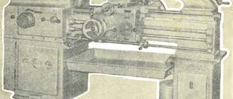
General view of the drilling machine 2A150
Photo of vertical drilling machine 2A150
Location of the components of the drilling machine 2A150
Location of the components of the drilling machine 2A150
List of components of the drilling machine 2A150
- plate;
- table;
- spindle;
- gearbox;
- spindle head;
- electric motor;
- handwheel for manual spindle feed;
- bed;
- handle for vertical movement of the table.
A box-shaped column 8 is mounted on the foundation slab 1. In its upper part there is a spindle head 5, which carries an electric motor 6 and a spindle 3 with a tool. A spindle head 4 is installed on the vertical guides of the column, inside which there is a feed mechanism that carries out the vertical movement of the spindle. The spindle can be raised and lowered mechanically or manually, using the steering wheel 7. To install and secure the device with workpieces being processed, there is a table 2. It is installed at different heights, depending on the size of the workpieces.
Kinematic diagram of the drilling machine 2A150
Kinematic diagram of the drilling machine 2A150
Kinematic diagram of a vertical drilling machine 2A150. View enlarged
In Fig. Figure 26 shows a kinematic diagram of a vertical drilling machine 2A150 (2N150).
The spindle speed is changed using a gearbox. The receiving shaft I rotates from the electric motor 46 through a belt drive 1-2. The movement of shaft II is transmitted by one of four pairs of gears 3-4, 5-6, 7-8 and 9-10. Further rotation is transmitted by one of the kinematic chains: 11-15, 16-17 or 13-14, 16-17 or 13-14, 18-19. Wheels 17 and 19 rotate the bushing 20, and with it the spindle V, connected to the bushing by a spline connection. As a result, the spindle has 12 different rotation speeds. The reversal of the spindle, necessary during thread-cutting operations, is carried out by switching the poles of the electric motor.
The working feed of the spindle is carried out using a rack and pinion transmission. The rack wheel 42 is in engagement with the quill rack 43. When the wheel rotates, the quill moves vertically along with the spindle. The described machine has nine feeds, carried out from the spindle through cylindrical gears 21-22, 23-24 and a feed box. Rotation is transmitted to shaft VIII by one of three gears 25-26, 27-28 or 21-30 and then to shaft X by one of three chains of gears 30-31, 32-33 or 30-31, 31-34 or 47-35 , 31-34. Gears 36-37 and a worm pair 40-41 impart rotation to the rack and pinion wheel 42.
Electrical equipment and electrical circuit of the drilling machine 2A150
Electrical diagram of drilling machine 2A150
Main technical characteristics of the machine 2A125, 2A150
Parameter name 2A125 2A135 2A150
| Basic machine parameters | |||
| The largest drilling diameter in steel is 45, mm | 25 | 35 | 50 |
| The smallest and largest distance from the end of the spindle to the table, mm | 0…700 | 0…750 | 0…800 |
| The smallest and largest distance from the end of the spindle to the plate, mm | 750…1125 | 705…1130 | 650…1200 |
| Distance from the axis of the vertical spindle to the rack guides (overhang), mm | 250 | 300 | 350 |
| Desktop | |||
| Maximum load on the table (center), kg | |||
| Dimensions of the working surface of the table, mm | 500 x 375 | 450 x 500 | 500 x 600 |
| Number of T-slots Dimensions of T-slots | 3 | 3 | 3 |
| Maximum vertical movement of the table (Z axis), mm | 325 | 325 | 325 |
| Spindle | |||
| Maximum movement of the spindle slide, mm | 200 | 200 | 250 |
| Maximum movement (stroke) of the spindle, mm | 175 | 225 | 300 |
| Spindle speed, rpm | 97…1360 | 68…1100 | 32…1400 |
| Number of spindle speeds | 9 | 9 | |
| Maximum permissible torque, kg*m | 250 | 400 | |
| Spindle taper | Morse 3 | Morse 4 | Morse 5 |
| Machine mechanics | |||
| Number of working feed stages | 9 | 11 | |
| Limits of vertical working feeds per spindle revolution, mm | 0,1…0,81 | 0,115…1,6 | |
| Maximum feed force, kg | 900 | 1600 | |
| Dynamic spindle braking | Eat | Eat | Eat |
| Electrical equipment and machine drive | |||
| Main motion drive electric motor, kW | 2,8 | 4,5 | 7,5 |
| Electric coolant pump Type | X14-22M | X14-22M | X14-22M |
| Dimensions and weight of the machine | |||
| Machine dimensions (length x width x height), mm | 980 x 825 x 2300 | 1240 x 810 x 2500 | 1550 x 970 x 2865 |
| Machine weight, kg | 870 | 1300 | 2250 |
Related Links
Catalog directory of metal-cutting drilling machines
Passports for metal-cutting drilling machines and equipment
Directory of woodworking machines
KPO Directory
Buy a catalog, directory, database: Price list of information publications
stanki-katalog.ru
2A125 vertical drilling machine. Purpose and scope
The vertical drilling machine 2A125 replaced the outdated model 2125
and was replaced by a more advanced model
2N125
.
The universal vertical drilling machine, model 2A125 , is designed for work in repair and tool shops, as well as in production shops with small-scale production of products; a machine equipped with accessories can be used in mass production.
Vertical drilling machine 2A125 , with a nominal drilling diameter of 25 mm, is used in enterprises with single and small-scale production and is designed to perform the following operations: drilling, reaming, countersinking, countersinking, reaming, threading and trimming ends with knives.
The machine allows a feed force of 900 kg, a torque of 2500 kgcm and comes with a 2.8 kW electric motor.
Drilling operations on machine 2a125
Operating principle and design features of the machine
The spindle of the 2A125 has nine rotation speeds with a control range of 97..1360 rpm from a mechanical gearbox.
The spindle feeds have both manual and mechanical drives from a 9-speed feed box with a control range of 0.1..0.81 mm per revolution.
The machine is equipped with a device for reversing the main movement electric motor, which makes it possible to cut threads using machine taps to a given depth with manual spindle feed.
Allows processing of parts in a wide range of sizes from various materials using tools from high-carbon and high-speed steels and hard alloys.
Placement category 4 according to GOST 15150-69.
Chronology of the plant's production of vertical drilling machines 2125 series with drilling diameters up to 25 mm:
- 2125 - the first model of a series of vertical drilling machines, produced from 1945 to 1950.
- 2A125, 2A125A, 2A125K - the next models in the series, produced from 1950 to 1965.
- 2N125, 2N125A, 2N125K, 2N125F2 - the most popular and widespread model of the series, produced from 1965 to the early 90s
- 2S125, 2S125-01, 2S125-04 are the latest models in the series. Discontinued in 2014
Analogs of vertical drilling machines 2A125 currently produced:
- 2T125, 2T140, 2T150 - manufacturer: Gomel Machine Unit Plant
- 2AS132, 2AS132-01 - manufacturer: Astrakhan Machine Tool Plant
- 2L125, 2L132, 2L135, LS25, LS35 - manufacturer: Lipetsk Machine Tool Enterprise (PJSC STP-LSP)
- MN25L, MN25N-01 - manufacturer: Molodechno Machine Tool Plant
Operations Performed
Using a vertical drilling machine model 2a125, it is easy to perform the following operations of the production cycle:
- Drilling holes up to 25 mm in diameter.
- Increasing the diameters of holes made using forging, stamping or casting.
- Reaming to produce holes with low roughness and more accurate dimensions and surface shape compared to drilling.
- Thread cutting on a vertical type 2a125 drilling machine differs from previous operations in the absence of forced tool feed.
- Countersinking is performed instead of drilling and is characterized by higher processing accuracy (up to 11th grade) and high productivity.
The unit meets all technical requirements, special or regulatory documents, questionnaires, and also has the necessary quality certificates. The accuracy of the equipment is confirmed by many companies; the machine performs fine processing of even small products made of different materials.
Photo of drilling machine 2A125
Photo of drilling machine 2A125
Photo of drilling machine 2A125
Photo of drilling machine 2A125
Machine equipment
Performing the listed operations, which require a lot of attention from craftsmen, using a 2a125 drilling machine, ensures the interaction of the following equipment elements:
- Bed – a stove and a table are mounted on it.
- A mechanism that ensures vertical supply of the working tool to the part.
- Speed boxes.
- Feed boxes.
- Cooling systems.
- Spindle for tool mounting.
And electrical equipment - it includes an electric motor capable of creating torque on the gearbox through a belt drive and an electric reverse mechanism.
To be allowed to work with this unit, a specialist must undergo training, testing for knowledge of safety rules, as well as regular medical examination. The equipment is not special or specialized, but the functionality of the unit is increased; not every master will be able to operate it correctly.
Working on such a unit requires high-quality lighting; the master must see the thread, its direction and the clarity of the work of the structural parts. Ventilation is suitable both natural and forced. The second option is required in large workshops.
Description of the kinematic diagram of the drilling machine 2A125
The kinematic chain (diagram in Fig. 2) serves for rotation and vertical movement (feed) of the spindle. The machine mechanisms are driven from an electric motor by means of an A1000 type V-belt transmission through pulleys 1 and 2. Pulley 2 sits on the first shaft of the gearbox, on which there is a movable triple block of gears 3, 4, 5, which transmits rotation to the second shaft through gears 6 fixedly mounted on it, 7 and gear 9 of the second triple block. A triple block of gears 8, 9 and 10 sliding along the second shaft through gears 11, 12 and 13 transmits rotation to the output shaft, which is a hollow sleeve (see Fig. 5). The splined end of the spindle moves freely along the splined hole of this shaft.
The feed mechanism receives movement along the following chain:
- from gear 14, sitting on the splined part of the spindle, through gears 15, 16 and 17, rotation is transmitted to a hollow roller, on which gears 18, 19 and 20 rotate freely, constantly meshed with gears 21, 22 and 23.
- Gears 23, 24 and 25 are constantly meshed with gears 26, 27 and 28, which rotate freely on the second hollow shaft. Inside both hollow rollers, pull keys move, blocking gears 18, 19, 20, 26, 27 and 28.
- From the second hollow roller through the cam clutch 29, rotation is transmitted to the worm 30 and the worm wheel 31, sitting on the same shaft with gear 32; the latter is engaged with a 33 rail, cut directly onto the spindle sleeve.
Thus, the rotational movement of the entire mechanism is converted into translational movement of the spindle. The spindle can also be moved by hand using a steering wheel mounted on a horizontal shaft. A gear 43 sits on a horizontal shaft, meshed with an internal gear 34 by a dial for setting the drilling depth.
The bracket is lifted by rotating the handle through the worm 38, the worm gear 37 and the rack gear 36, which engages with the rack 35 mounted on the column of the machine.
The table is raised by rotating the handle through bevel gears 40 and 39, screw 42 and nut 41.
Brief description of individual components of the 2A125 vertical drilling machine
Gearbox of vertical drilling machine 2A125
Kinematic diagram of the drilling machine 2A125
The gearbox is a cast iron housing, inside of which there is a spindle gear reducer and a gear shift mechanism.
The gearbox is driven by a vertically located electric motor through a V-belt drive. The electric motor is mounted on a bracket that can move along the axis of the box, which ensures belt tension. The bracket is clamped in any position by tightening two bolts 1.
By moving the two triple blocks of gears 2 and 3, nine different spindle speeds are obtained. Switching is carried out using forks controlled by two handles located on the left cover of the gearbox housing (Table 1).
Shaft 4 of the gearbox is a hollow sleeve, the spline hole of which transmits rotation to the machine spindle.
The rest of the box rollers are splined, which greatly simplifies assembly. The entire gearbox mechanism is lubricated by a special pump located under casing 5.
The gearbox housing is mounted on a special cast iron stand.
Feed box for vertical drilling machine 2A125
Feed box for vertical drilling machine 2A125
The feed box (Fig. 5) is installed in the feed mechanism housing. The feed box is driven by gear 1, which sits directly on the spindle splines and meshes with double gear 2, sitting on the axis. Gear 2 transmits rotation through gear 3 to a double cone 4 with draw keys.
The draw keys are controlled by handles placed on the front part of the bracket. Roller 5 of the second cone has end cams that engage with a jaw clutch sitting on the worm of the feed mechanism.
The feed box carries out nine feeds within the range of 0.1..0.81 mm per spindle revolution (Table 2).
Feed mechanism
Feed box for vertical drilling machine 2A125
The feed mechanism housing is a rigid cast iron casting, inside of which, in addition to the feed mechanism, there is a spindle and a feed box mechanism.
The feed mechanism is driven by the feed box through the cam clutch 1, which serves to turn off the mechanical feed from the cam 18 installed on the limb 19. The same clutch plays the role of a safety device in case of overload.
Using screw 2 and spring 3, the clutch is adjusted to disengage (click) at a feed force exceeding the rated force by 10%, i.e. at a force of 1000 kg.
The mechanical feed can be turned off at any time by rotating the steering wheel 4 in the opposite direction, i.e., away from you.
To adjust the drilling depth, the end of the drill is manually brought into contact with the part, and the edge of the cam 22 is aligned with the division of the dial 19, corresponding to the drilling depth.
The operating principle of the feed mechanism is as follows: by rotating the steering wheel 4 towards ourselves, we will rotate the coupling connected to it by 20° relative to the shaft. The angle of 20° is limited by the slot on the coupling and pin 6.
In this case, the teeth of the coupling 5, due to the bevel, shift the cage 7 in the axial direction and, entering the end face onto the end of the teeth of the cage, fix this displacement. A double-sided ratchet disk 8 sits on the holder, connected to the holder by spring pawls 9.
When the cage is displaced, the teeth of the disk enter the teeth of the second disk 10, attached to the worm wheel 11.
Since the chain is closed by the ends of the teeth of the coupling 5 and the cage 7, the rotation of the worm wheel 11 is transmitted to the shaft 12. With further rotation of the steering wheel 4 with the feed turned on, the pawls 9 sitting in the cage 7 slip over the teeth of the inner side of the disk 8, and thus the mechanical feed is manually advanced.
When manually turning off the feed by turning the steering wheel 4 in the opposite direction by 20° relative to the shaft 14, we install the tooth of the coupling 5 against the cavity of the holder 7. The holder 7, due to the axial force arising due to the inclination of the teeth of the disks 8 and 10 and the special spring 13, moves to the right and disengages the disks. Mechanical feed stops.
The feed mechanism allows manual feeding of the spindle with a steering wheel directly through the rack and pinion gear 14 and the spindle sleeve 15, for which it is necessary to turn off the mechanical feed with the steering wheel 4, and then move the ring 16 along the axis of the shaft 12 away from you, while the pin 17 blocks the pin 16.
Thus, the rotation of the steering wheel 4 is transmitted directly to the horizontal shaft 12. Since when the feed is turned off by the cam 22 through the clutch 1 on the worm 20, the horizontal shaft 12 is not released, the rotating tool does not move away from the part and cleans the surface being processed, which is especially important during trimming work .
Thanks to the presence of an electric reverse, controlled both manually and automatically, it is possible to cut threads by manually approaching and retracting the tap.
When, by manually controlling the reverse, the required cutting depth is obtained using handle 21, we switch the direction of rotation of the spindle and remove the tap. With automatic reverse, the cutting depth is adjusted by Cam 18 located on dial 19, which switches when the required depth is obtained.
When cutting threads, a safety chuck should be used.
The bracket can be easily moved along the column guides manually using a crank handle, thanks to the worm and rack pairs.
If it is necessary to move the bracket along the guides, the wedge of the bracket must be pre-pressed.
The bracket is clamped in any position using a wedge and a key.
Work on the machine should be carried out after completely tightening all the bolts of the bracket wedge.
The feed mechanism and feed box are lubricated by a special pump installed in the feed box.
Spindle
Spindle of vertical drilling machine 2A125
The spindle with bearings (Fig. 7) is mounted in a sleeve, which in turn is guided by bracket bushings.
Spindle 1 rotates in ball bearings 2. The axial feed force is perceived by thrust bearing 3 mounted in cup 4.
The bearings are adjusted by tightening the nut through the window located on the front part of the bracket.
The spindle is balanced by a weight placed in the machine column.
The spindle bearings are lubricated with a wick from the cavity of the feed box.
The oil supply should be one drop per minute.
Spindle bearings for drilling machine 2A125
The spindle of the 2A125 machine is mounted on 3 bearings:
- 2. Lower bearing No. 206 single-row radial ball bearing, accuracy class B(5), size 30x62x16 mm
- 3. Bearing No. 8306 thrust ball, accuracy class N(0), 30x60x21
- 2. Upper bearing No. 206 single-row radial ball bearing, accuracy class H(0), size 30x62x16 mm
Technical characteristics of bearing No. 206
Bearing 206 is an open type single row deep groove ball bearing.
Designed to withstand radial loads at high rotation speeds. This type of bearing is used everywhere in all industries and agriculture. In terms of the number of units sold, this bearing is only inferior to exactly the same one, but one size smaller - 205. Basically, such a bearing is bought as a closed type - 180206, and it is this bearing that is produced in large volumes at bearing factories. The design - radial ball - is designed to absorb radial loads and, to a very small extent, axial loads.
In addition to these two modifications, there are 80206 (closed on both sides with metal washers), 60206 (closed on one side) and 50206 - with a groove along the outer ring for a retaining ring (the latter type is used quite rarely). Bearings are produced mainly of class 6 precision, they are intended for the mass consumer. For the needs of individual industries, various modifications are produced with additional operating requirements (requirements for noise, accuracy, resistance to temperature or chemical influences), increased load capacity (indicated by the letter A to the right of the main designation).
The main manufacturing plants in our country are JSC SPZ (Saratov, 3 GPP), VBF (Vologda, 23 GPP), LLC SPZ-4 (Samara) and 2 GPP (Moscow). The last two factories assemble bearings from Chinese components, produced with quality control from normal metal (unlike brands such as CRAFT, SZPK, hb and others), which makes them lower in price with decent performance characteristics. Bearings for the mass consumer are produced in accordance with GOST 520-2002, special modifications are made in accordance with TU and ETU and are supplied directly from one plant to another, bypassing the dealer network.
You can buy bearings of this type at minimal prices from official dealers of factories.
The approximate price of the product depends very much on the manufacturer and ranges from 34 - 35 (China) to 280 - 300 rubles (SKF). Bearings with protective washers and plugs are slightly more expensive than open ones. Russian bearings are closer in price to Chinese ones, but in quality they are much better.
Imported bearings of this standard size are designated as 6206 /Рх (where x is the accuracy class of the manufactured bearing and varies from 2 to 6) with additional designations of protective washers and plugs as Z, ZZ or 2RS. For example, 6206 2RS is the designation for bearing 180206 adopted by the manufacturer FAG.
Bearing 180206 (closed, analogue - 6206 2RS) is widely used in domestic automotive and agricultural equipment.
Dimensions and characteristics of bearing 206 (6206)
- Inner diameter (d): – 30 mm;
- Outer diameter (D): – 62 mm;
- Width (H): – 16 mm;
- Weight: – 0.21 kg;
- Number of balls in the bearing: - 9 mm;
- Ball diameter: - 9.525 pcs;
- Dynamic load capacity: - 19.5 kN;
- Static load capacity: - 11.2 kN;
- Maximum rated speed: - 7500 rpm.
Bearing diagram 206 (6206)
Machine lubrication
The oil used to lubricate the machine must be clean, acid-free, and free of water and solid particles.
It is recommended to use industrial oil grade “20” (spindle “3”) GOST 1707-51.
The gearbox mechanisms are lubricated by a special pump that supplies oil from an oil reservoir in the gearbox support.
During operation of the machine, oil is sprayed by rapidly rotating gears, due to which it gets onto all working surfaces of the gearbox mechanism.
The gears of the feed box and feed mechanism are lubricated by a pump installed in the feed box, which supplies oil from the lower cavity of the bracket housing.
The guide columns, the surface of the cup and the splined part of the spindle are lubricated daily on top. To fill the gearbox with oil, 3 liters are required, and for the bracket - 1.5 liters of oil.
The oil should be changed the first time after 12-15 days, the second time after 20-25 days, then once every 3 months. The oil is drained through the drain holes provided in the gearbox and in the bracket.
When changing oil, the mechanisms must be washed with clean kerosene. Before filling, the oil should be filtered. During operation, it is necessary to monitor the operation of the gearbox and feed rate oil pumps, as well as the oil supply to the spindle bearings.
Adjusting and setting up the machine
After installing the machine at the workplace, cleaning, filling with oil and lubricant, connecting to the electrical network, checking operation at all speeds and feeds, no additional adjustment is required.
Setting up the machine consists of installing the table and bracket in the positions required for operation, clamping the bracket wedge and setting the speed and feed rates.
The clearances in the spindle bearings are selected through a window on the front wall of the bracket, closed with a lid. To carry out adjustment, it is necessary to turn the spindle so that the adjusting nut screw is in the window; then, loosening the screw, tighten the nut and tighten the screw again.
The drilling depth is set using a dial as follows (see Fig. 6): by rotating the cross steering wheel towards you, lower the spindle until it comes into contact with the workpiece. We unscrew the screw of the feed cut-off cam 22 and the cam 18, turn the cam 22 until its edge coincides with the division of the dial corresponding to the drilling depth, and tighten the screws again.
In this case, the division on the dial corresponds to the full drilling depth, including the conical part of the drill sharpening.
Cam 18 is used to configure automatic reversal of the spindle direction when cutting threads. The installation of this cam is similar to the installation of the mechanical feed switching cam. In this case, the feed cut-off cam is moved back 10 mm.
The spindle rotation direction is changed by reversing the electric motor.
The knurled cap, located in the center of the cross wheel, is used to turn off the mechanical feed when it is necessary to perform drilling or cutting with manual feed. To turn on manual feeding, the cap must be pressed away from you until it stops.
The belts are tensioned by moving the bracket with the electric motor installed on it using tension screws placed on the side wall of the bracket.
To tighten the spring of the safety clutch, which turns off the feed when overloaded, use a special screw with an internal hexagonal hole, located under the cap of the upper cover of the bracket. Normally, the spring is adjusted to turn off the feed when an axial force exceeds the rated feed force by 10%, i.e., at a force of 1000 kg.
Characteristics
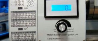
The vertical drilling machine 2S125 has a reversible AC motor with an industrial frequency of 50 Hz, which increases the capabilities of material processing, especially when cutting threads with machine taps. The main technical characteristics are as follows:
- rotation speed – from 90 to 2800 rpm;
- number of speeds – 9;
- limits of hole diameters in steels of low and medium hardness – from 3 to 31 mm;
- thread cutting limits – from M3 to M22;
- maximum workpiece height – 900 mm;
- the distance from the spindle axis to the column is 320 mm.
General view of the vertical drilling machine 2S125
Model 2C125 has a three-phase electric motor designed for connection to an industrial three-phase electrical network of 380 V. Depending on customer requirements, the manufacturer can install a working electric motor with a power of 1.1 or 1.3 kW with a rotor speed of 1110 or 1360 rpm, respectively.
For ease of operation, the vertical column has a rectangular table, which can either rotate around the column or move vertically along it using a rack and pinion gear. When placing a workpiece on a table, its maximum height size is limited to 500 mm. The maximum weight of the workpiece placed on the table should not exceed 100 kg.
The table and base of the device each have three T-shaped fastening grooves for installing fastening devices. The width of the groove is 14H12. The distance between the grooves is 80 mm.
The spindle has a manual feed, with a maximum travel height of 150 mm. The height is controlled by the drill depth indicator on the front of the drill head. To prevent spontaneous lowering of the spindle, the machine is equipped with a spring counterweight.
To fasten the working tool, this model is equipped with an internal Morse taper 3. This allows you to quickly change the working tool for various technological operations.
General view of the vertical drilling machine 2S125
Machine 2S125 - side view
Machine 2S125 - front view
The modification of the 2C125-04 model has the ability to automatically feed the spindle, which is important when cutting threads in holes with machine taps.
Electrical equipment and electrical circuit of the drilling machine 2A125
Electrical diagram of a vertical drilling machine
List of elements of the electric vertical drilling machine 2A125
- Drive motor A42-4
- Thermal relay
- Fuse HE-27
- Input switch VP-25
- Light switch VT-1
- Lighting lamp
- Step-down transformer TPV-50
- Microswitch MP-1
- Microswitch MP-1
- Microswitch MP-1
- Coolant pump switch VPZ-10
- Electric coolant pump PD-22
1K, 2K — Magnetic starters MPKO-111
Electrical equipment of a vertical drilling machine 2A125. General information
Electrical equipment of the machine (Fig. consists of the following components:
- three-phase squirrel-cage asynchronous electric motor on feet type A 42/4 with a power of 2.8 kW, used for spindle rotation and tool feed
- electric pump PD-22 with a power of 0.125 kW
- starting and protective equipment built into the niche of the machine column
- command equipment, consisting of three microswitches controlled from the handle
- switching wires running mainly along the internal cavities of the column
Description of the electrical circuit of the vertical drilling machine 2A125
- By turning on the input switch 4, voltage is supplied to the starting and control equipment. Switch 11 of the pump is used to turn on the cooling
- In the initial (middle) position of the handle, the pin acts through a spring on microswitch 10, the contacts of which (a and b) are open and the control circuit is de-energized
- To start the machine, the control handle is moved down, while contacts a and b of microswitch 10 and contacts b and c of microswitch 9 are closed, starter 1K and electric motor 1 are turned on. When the handle is lowered, contacts b and c open, the coil of starter 1K is powered through circuit a - b - g - c - g.
- If the machine was configured for drilling, then at the end of processing, depending on the setting, the feed is turned off without turning off the rotation. The spindle is retracted manually.
- If the machine was configured for thread cutting, then upon completion of cutting, the cam mounted on the limb, through a special mechanism, acts on the microswitch 8, the contacts b and d of which open and the 1K starter is turned off, closing contacts b and d, as a result of which the reversing starter 2K is turned on . The engine is reversed, the tap is unscrewed from the product. When the tap is removed, contacts b and d of the microswitch open, and the 2K starter is powered through the block contacts along the circuit a - b - f - d - h
- For the next operation, it is necessary to press the control handle to the “right” position, turning off the 2K starter; the power circuit is opened at points b and e and the 1K starter is turned on along the circuit a - b - c - g
- At any time, the machine can be turned off by moving the handle to the middle position, and the engine can be reversed manually by moving the handle up
Protection of electrical equipment of a vertical drilling machine 2A125
The circuit provides protection against short circuit, overload and zero protection.
The bracket is grounded by an additional conductor.
The machine must be grounded, for which there is a special bolt.
Maintenance of electrical equipment is carried out according to standard instructions.
Main technical characteristics of the 2A125 machine
| Parameter name | 2A125 | 2A135 | 2A150 |
| Basic machine parameters | |||
| The largest drilling diameter in steel is 45, mm | 25 | 35 | 50 |
| The smallest and largest distance from the end of the spindle to the table, mm | 0… 700 | 0… 750 | 0… 800 |
| The smallest and largest distance from the end of the spindle to the plate, mm | 750… 1125 | 705… 1130 | 650… 1200 |
| Distance from the axis of the vertical spindle to the rack guides (overhang), mm | 250 | 300 | 350 |
| Desktop | |||
| Maximum load on the table (center), kg | |||
| Dimensions of the working surface of the table, mm | 500 x 375 | 450 x 500 | 500 x 600 |
| Number of T-slots Dimensions of T-slots | 3 | 3 | 3 |
| Maximum vertical movement of the table (Z axis), mm | 325 | 325 | 325 |
| Spindle | |||
| Maximum movement of the spindle headstock (spindle slide), mm | 200 | 200 | 250 |
| Maximum movement (stroke) of the spindle, mm | 175 | 225 | 300 |
| Spindle rotation speed, rpm (number of steps) | 97… 1360 (9) | 68… 1100 (9) | 32… 1400 (12) |
| Number of spindle speeds | 9 | 9 | 12 |
| Maximum permissible torque, N*m (kgf*m) | 250 | 400 | 800 |
| Spindle taper | Morse 3 | Morse 4 | Morse 5 |
| Machine mechanics | |||
| Number of working feed stages | 9 | 11 | 9 |
| Limits of vertical working feeds per spindle revolution, mm (number of steps) | 0,1… 0,81 (9) | 0,115… 1,6 (11) | 0,12… 2,64 (9) |
| Maximum feed force, N (kgf) | 9000 (900) | 16000 (1600) | 25000 (2500) |
| Dynamic spindle braking | Eat | Eat | Eat |
| Electrical equipment and machine drive | |||
| Main motion drive electric motor, kW | 2,8 | 4,5 | 7,5 |
| Electric coolant pump Type | X14-22M | X14-22M | X14-22M |
| Dimensions and weight of the machine | |||
| Machine dimensions (length x width x height), mm | 980 x 825 x 2300 | 1240 x 810 x 2500 | 1550 x 970 x 2865 |
| Machine weight, kg | 870 | 1300 | 2250 |
- Universal vertical drilling machine model 2A125. Description and service manual, 1960
- Barun V.A. Working on drilling machines, 1963
- Vinnikov I.Z., Frenkel M.I. Driller, 1971
- Vinnikov I.Z. Drilling machines and work on them, 1988
- Loskutov V.V Drilling and boring machines, 1981
- Panov F.S. Working on CNC machines, 1984
- Popov V.M., Gladilina I.I. Driller, 1958
- Sysoev V.I. Handbook for a Young Driller, 1962
- Tepinkichiev V.K. Metal cutting machines, 1973
Bibliography:
Related Links. Additional Information
- Classification and main characteristics of drilling-milling-boring group of machines
- Selecting the right metalworking machine
- Machine repair technology
- Methodology for checking and testing drilling machines for accuracy and rigidity
- Directory of drilling machines
- Manufacturers of drilling machines in Russia
- Manufacturers of metal-cutting machines
Home About the company News Articles Price list Contacts Reference information Interesting video KPO woodworking machines Manufacturers
Vertical drilling machine 2С125
Price as of January 27, 2018 - request price
| Buy | Add to comparison |
The 2S125 vertical drilling machine is designed for drilling, reaming, countersinking, countersinking, reaming and threading in various types of metal and non-metallic parts using high-speed and carbide tools.
- 9 spindle speeds
- 3 automatic spindle feeds for machine 2С125-04
- Overload clutch
- Work table with height adjustment mechanism based on rack feed 420x300mm
- Working surface base 320x320
Characteristics 2S125 2S125-04
| Nominal diameter of drilling in steel, mm | 25 | 25 |
| Largest drilling diameter in steel, mm | 31 | 31 |
| Range of threads to be cut | M5-M22 | M5-M22 |
| Working surface size, mm | 420×300 | 420×300 |
| Number of T-slots | 3 | 3 |
| Center groove width | 14h22 | 14h22 |
| Slab working surface size, mm | 320x320 | 320x320 |
| Number of T-slots | 3 | 3 |
| Center groove width | 14h22 | 14h22 |
| Maximum distance from the end of the spindle to the table, mm | 730 | 730 |
| Maximum distance from the end of the spindle to the plate, mm | 1210 | 1210 |
| Table lift, mm | 680 | 680 |
| Distance from spindle axis to column, mm | 320 | 320 |
| Spindle taper | Morse 3 | Morse 3 |
| Mechanical feed of spindle quill, mm | — | 0,05…0,1; 0,1; 0,2 (0,28; 0,56) * |
| Spindle quill movement, mm | 150 | 150 |
| Number of spindle speeds | 9 | 9 |
| Number of mechanical feeds of the spindle quill | — | 3 |
| Spindle speed range, rpm | 90-1400 (180-2800)* | |
| Main movement motor power, kW | 1,5 (1,1)* | 1,5 (1,1)* |
| Maximum weight of the workpiece, kg | 100 | 100 |
| Maximum height of the workpiece on the table, mm | 500 | 500 |
| Maximum height of the workpiece on the plate, mm | 900 | 900 |
| Weight 2S125 machine 2S125, kg (with packaging) | 585 | 585 |
| Weight of 2S125 machine, kg (without packaging) | 430 | 450 |
| Overall dimensions, mm (with packaging) | 1100x760x2260 | 1100x760x2260 |
| Overall dimensions, mm (without packaging) | 800x500x2050 | 800x500x2050 |
| *optional |
DELIVERY SET: — The machine is assembled;
— Key to electrical cabinet D73-72; — Handle for raising the table and drilling head; — Technical documentation (Operation Manual). ADDITIONAL EQUIPMENT (supplied at extra cost): — Drill chuck 6150-4029-03; — Adapter bushings according to Morse cones; — Fixed machine vice 7200-0209-02 (125 mm) or 7200-0214-02 (160 mm); — Rotary machine vice 7200-0210-02 (125 mm) or 7200-0215-02 (160 mm); — Thread-cutting chuck 6162-4003-01 (M3-M12); — Set of safety heads for thread-cutting chuck 6162-4003-01 (M3-M12); — head 6251-4002M-01 (M4); — head 6251-4002M-02 (M5); — head 6251-4002M-03 (M6-M8); - head 6251-4002M-04 (M8-M10); — head 6251-4002M-05 (M10); - head 6251-4002M-06 (M12); — Thread-cutting chuck 6162-4003-02 (M14-M24); — Set of safety heads for thread-cutting chuck 6162-4003-02: — head 6251-4002M-07 (M14); - head 6251-4002M-08 (M16); - head 6251-4002M-09 (M18-M20); - head 6251-4002M-10 (M22); — Fencing of the cutting zone; — Lighting; — Coolant supply system. rustan.ru