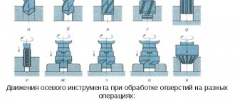
A vertical drilling machine is a technique necessary for creating blind and through holes, as well as for additional processing of holes obtained by other methods. It is often used for drilling holes that require maximum precision.
Also, units of this type demonstrate their effectiveness when cutting internal threads and when creating discs from solid sheet material. In other words, vertical machines are universal assistants that can be assigned to perform a number of difficult tasks.
Of course, the technological capabilities of the equipment are not limited to the above operations. The functionality of the technology is much wider than it might seem at first glance. This has become the reason for its widespread use in a variety of fields.
Such machines have gained particular popularity in small-scale production. They are ideal for performing private tasks. However, if the workshop is properly equipped, such units will become an indispensable tool in the field of mass production.
Information about the manufacturer of the vertical drilling machine 2Р135Ф2
The manufacturer of drilling machines models 2Р135Ф2, 2Р118Ф2, 2Н125, 2Н135, 2Н150, 2Г175 is the Sterlitamak Machine Tool Plant , founded in 1941.
The history of the Sterlitamak Machine Tool Plant begins on July 3, 1941, when the evacuation of the Odessa Machine Tool Plant to the city of Sterlitamak began.
Already on October 11, 1941, the Sterlitamak Machine Tool Plant began producing special modular machines for the defense industry.
Currently, the plant produces metalworking equipment, including CNC lathes and milling machines, multifunctional machining centers.
Products of the Sterlitamak Machine Tool Plant
- 2135
— universal vertical drilling machine, Ø 35 - 2A125
- universal vertical drilling machine, Ø 25 - 2A135
- universal vertical drilling machine, Ø 35 - 2A150
- universal vertical drilling machine, Ø 50 - 2G175
- universal vertical drilling machine, Ø 75 - 2N125
- universal vertical drilling machine, Ø 25 - 2N135
- universal vertical drilling machine, Ø 35 - 2N150
- universal vertical drilling machine, Ø 50 - 2R135F2
- CNC vertical drilling machine, Ø 35 - 2С50
- universal vertical drilling machine, Ø 50 - 2S125, 2S125-1 (2S125-01), 2S125-04
- universal vertical drilling machine, Ø 25 - 2S132, 2S132K
- universal vertical drilling machine, Ø 32 - 2С150ПМФ4
- vertical drilling-milling-boring machine with CNC and ASI, 500 x 1000 - 2С550А
– radial drilling machine, Ø 36 - 400V
- vertical drilling-milling-boring machine with CNC and ASI, 400 x 900 - 500V (STC F55)
- vertical milling center, 630 x 1200 - SF-16, SF-16-02, SF-16-05
- tabletop milling and drilling machine, Ø 16
Types of machines
A drilling machine is a table-top unit with mechanisms and manual controls, which has a vertical drilling movement of the head.
During operation, a floor-standing unit is more comfortable than a tabletop unit.
The radial drilling unit has the appearance of a massive apparatus and is mounted on a plate, and the sleeve is an important advantage of the machine.
A modern drilling machine with a CNC system is used in production with high precision processing, which carries out technological work. The CNC system will accurately calculate the entire trajectory of the nozzle and execute the programmed shape.
The cost of CNC equipment is significantly higher than without it.
2Р135Ф2 vertical drilling machine with CNC. Purpose and scope
Vertical drilling machine 2Р135Ф2 with a six-spindle turret head, with a cross table and numerical control (CNC) is designed for drilling, reaming, countersinking, reaming, threading and milling in small-scale and mass production of various industries.
2R135F2 drilling machine is used for processing body parts and parts such as “flange”, “cover”, “plate”, “lever”, “bracket”.
The electrical circuit and CNC make it possible to carry out the following technological operations on the machine:
- Drilling;
- End trimming (countering);
- Boring;
- Threading;
- Deep drilling;
- Milling.
Operating principle and design features of the machine
The presence on the machine of a six-spindle turret for automatic tool change, a cross table with program control allows for coordinate processing of parts such as covers, flanges, panels without preliminary marking and the use of jigs.
2R135F2 vertical drilling machine has large ranges of spindle speed and feed rates, which fully ensure the choice of standard cutting modes when processing various structural materials.
2R135F2 machines ensure the accuracy of the center distances of machined holes up to 0.10-0.15 mm and can operate in an automatic cycle (in this mode, multi-operational processing of parts with a large number of holes is performed).
Design of the machine 2Р135Ф2 . A column is mounted on the base of the machine, along the rectangular vertical guides of which the spindle head (support) carrying the turret moves. The gearbox and feed reducer are rigidly mounted on the column. The cross table has a base along which the slides carrying the table itself move in the transverse direction. The latter, in turn, can move in the longitudinal direction along the slide guides. The movement of the slide and table is carried out from the gearboxes.
Numerical control system . The machine model 2Р135Ф2 is equipped with a numerical control device “ Coordinate S70-3 ”, the machine model 2Р135Ф2-1 is equipped with a CNC device 2П32-3 , which ensure simultaneous movement of the table along the X and Y axes when positioning control of movement along the axis (from the coordinate), makes it possible to control by turning the turret, select the value of the working feed and spindle speed. The device has a digital display and allows for input of corrections for tool length.
The positional rectangular CNC system is closed; code converters are used as measuring devices. The positioning accuracy of the table and support is 0.05 mm, the discreteness of programming and digital display is 0.05 mm. Number of controlled coordinates: total - three; simultaneously - two.
The design organization is the Experimental Research Institute of Metal-Cutting Machine Tools (ENIMS) and the Sterlitamak Machine Tool Plant named after. V.I. Lenin.
2R135F2 machine was accepted for serial production in 1979.
The accuracy class of the machine is N according to GOST 8-77. The quality category is the highest.
Explanation of symbols
An alphanumeric designation is applied to the body of each model of a vertical drilling machine, indicating the characteristics of the equipment.
The first digit indicates whether the unit belongs to a certain group, the second indicates the type of mechanism, and the third and fourth indicate the dimensions. Sometimes a letter is placed after the first number. It informs you that this model has improved characteristics. If the letter appears after all the numbers, then the machine is improved on the basis of some unit. Depending on the parameters and characteristics, the price of a vertical drilling machine can fluctuate over a fairly wide range.
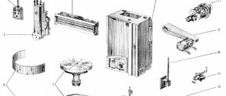
Location of the main parts of the drilling machine 2Р135Ф2
Location of the main components of the 2р135ф2 machine
Designation of the main parts of the drilling machine 2Р135Ф2
- Machine base
- Table slide
- Turret
- Spindle head (caliper)
- Gearbox
- Feed reducer
- Control pendant
- Cabinet with electrical control equipment
- Cabinet with CNC equipment
- Column
- Cross table
On the base (bed) 1 of the machine there are slides 2 of the cross table, which has telescopic protection for the guides. A spindle head moves along the vertical guides of the column, on which a six-spindle turret head is mounted, allowing automatic tool change according to a control program. To speed up manual tool replacement, a special pressing device is provided in the turret. The machine can be controlled from a pendant control panel.
Movements in the machine
- The main movement is the rotation of the spindle with the tool
- Movement along the machine axes:
- X-axis - longitudinal feed - longitudinal movement of the table along the slide guides
- Y axis - transverse feed - transverse movement of the slide along the bed guides
- Z axis - vertical feed - vertical movement of the spindle head (support) along the rack guides
To control table movements (X and Y coordinates) from a program recorded on punched tape, machines are equipped with various CNC devices (one of the most common is the CNC “Coordinate S-70”). Feed along the Z coordinate is carried out in cyclic control mode. For coordinate movements of the table, manual data input on the CNC console can also be used. The presence of a digital display allows you to visually monitor the position of the table, as well as monitor the correctness of the program recording on punched tape.
The machines provide feedback on the position of the working bodies on each of the two movements controlled by the punched tape. Circular electrical contact code converters are used as feedback sensors. Movements of the turret head during fast and working strokes in both directions are limited by adjustable cams acting on switches (electric stops).
Application and description of the drilling machine 2S132L:
for drilling work on metal, these are usually large and tall workpieces; a vice with a workpiece can be installed on the base of the machine or on a rotary tilting table. The rotation of the desktop is carried out by a round column. The 2S132L drilling machine can be used in workshops for small jobs and in industrial production for serial work. The drill feed is manual or mechanical, gear shifting is geared. Productivity can be single, when constant readjustment is required when changing workpieces, or serial, for this purpose the machine has automatic tool feeds into the processing zone.
Kinematic diagram of the drilling machine 2Р135Ф2-1
Kinematic diagram of the drilling machine 2р135ф2-1 with CNC 2П32-3
The kinematic diagram of the machine (Fig. 4.6) consists of the following independent kinematic chains: main movement drive (rotation of the turret spindles); cross table feed drive; caliper drive with turret head; turning the turret head; pressing tools out of spindles.
Main movement chain
Main movement chain: two-speed asynchronous electric motor M1 (N = 4/4.5 kW; n = 1470/990 rpm) - 29/41 gear transmission - shaft I - shaft II (through gears 24/48 and 36/36 at engaged couplings M1 and M2 or through gear 14/36 with engaged coupling M3) - shaft III (via gears 14/36 and 48/24 with engaged couplings M4 and M5) - shaft V through bevel gear 21/21 - to one of turret spindles through 35/42 gears; 31/49; 49/47; 47/35.
Cross table feed drive chain
The feed drive chain of the cross table has two gearboxes, one of which moves the table along the slide (X-axis), and the second drives the movement of the slide along the frame (Y-axis).
Kinematic chain of the slide drive
The kinematic chain of the slide drive ensures their fast, medium and slow movements. Fast movement (at a speed of 7000 mm/min): M4 electric motor (N=0.6 kW; p=1380 rpm) - 16/40 gears; 34/22; 22/52; 52/34 - ball screw.
Moving at medium speed (200 mm/min): M4 electric motor - 16/64 gears; 25/55; 25/55; 38/42; 22/52; 52/34 - ball screw. Slow movement (at a speed of 50 mm/min): M4 electric motor - 16/64 gears; 25/55; 25/55; 16/64; 22/52; 52/34 - ball screw. A feedback sensor is mounted on the ball screw.
The table moves along the slide from the M5 electric motor (N = 0.6 kW; n = 1380 rpm); the kinematic chain of the drive of this movement is similar to the kinematic chain of the drive of the slide movement.
Turret Caliper Drive Chain
Caliper drive chain with turret head: DC electric motor M2 (N = l.3 kW; n = 50..2600 rpm) - 13/86 gear (or 37/37 gear - 4/25 worm gear - lead screw, equipped with a brake clutch (preventing arbitrary lowering of the caliper when the electric motor is turned off) and a remote control feedback sensor.
Turret rotation drive chain
Turret head rotation drive chain: M3 electric motor (N=0.7/0.9 kW; n= 1400..2700 rpm) - 23/57 gear - 1/28 worm gear - 16/58 gear - turret body .
Pressing tools out of spindles
Pressing tools out of spindles: M3 electric motor - 18/52 gear (with the clutch engaged) - 1/28 worm gear - 21/21 gear - eccentric mounted in the groove of the turret head rotation axis and pressing tool.
Lubricating the turret support
Lubrication of the turret head support is carried out forcibly according to the following scheme: MZ electric motor - 18/52 gears; 52/75 - EZ eccentric, driving the plunger pump.
Gearbox lubrication
The gearbox is lubricated by a gear pump driven by the gearbox electric motor through a V-belt. The oil supplied by the pump enters the distribution chamber, where it is distributed to lubricate all moving parts of the gearbox and electromagnetic clutches, and then drained into the reservoir. The oil level is controlled by an oil indicator.
Lubrication of caliper feed gearboxes and cross table
Lubrication of the caliper feed gearboxes and the cross table is carried out by spraying oil onto the gears. The oil level is monitored visually using oil indicators.
Lubricating the guides and screw pairs of the cross table
The guides and screw pairs of the cross table are lubricated manually using a lubricator. The bearings of the turret spindles are lubricated with grease.
Coolant supply
The coolant is supplied from a centrifugal pump. To cool the tool in the cutting zone, an individual drive is provided, which allows you to direct a stream of coolant to the desired location. The supply of coolant in the automatic cycle begins when the caliper moves down (the beginning of the working feed) and stops when the caliper begins to return to its original position (in this case, the corresponding toggle switch must be turned on on the control panel).
Electrical equipment of the machine
The electrical equipment of the machine consists of a separate cabinet of relay automation and CNC, as well as elements installed directly on the machine. Electrical connections between the machine components and the CNC are made by harnesses in metal hoses ending with connectors.
The electrical circuit of the machine provides the following operating modes:
- commissioning;
- semi-automatic with task input from CNC switches;
- semi-automatic with task input from punched tape;
- automatic with task input from punched tape.
The mode is selected using switches located on the control panels of the machine and the CNC.
What to consider when choosing?
We have described more than one really good drill for the home; the rating of the best models for a workshop or enterprise also includes quite a few options. So which one will be the best choice? You should purchase a model that meets the following parameters:
- Power – if you plan to use the equipment frequently and get high performance from it, the power should be at least 600 W.
- Hole diameter - at home you hardly need to make it larger than 16 mm, but in factories and factories you often have to make sections of 50-60 mm.
- Ease of use - the more compact and lighter the machine, the more speeds it supports, the more ergonomic it is, the more convenient it is to use, but also the easier it is to troubleshoot.
- Security – make sure the option you like has a transparent screen and cannot be turned on by itself.
We hope you can now make your decision easily. And if you have any questions, contact us: we will tell you which domestic drill is better, Optima, ZUBR or DILD, which are the best American, German, Chinese models and give them to you at a competitive price.
Setting up the machine
Regardless of the position of the operating mode switch on the CNC console, the adjustment mode is turned on by switch 23 located on the machine control panel (Fig. 4.7). In the adjustment mode, carried out by means of controls located on the machine console, the following is performed: turning the turret to a given position; pressing out the tool; turning spindle rotation on and off; moving the table along the X and Y axes in accordance with the selected speed and direction; moving the turret support along the Z axis in accordance with the task.
Machine control panel 2р135ф2-1
Setting the working parts of the machine to the zero position
The working parts of the machine are set to the zero position automatically before the “Program Entry” command. When button 15 is pressed, the turret support quickly rises until the limit switch is activated along the Z coordinate. The table moves until the limit switches are activated along the X and Y coordinates, and at the same time commands are sent to the CNC about the initial position of the working parts. The installation cycle is complete.
Rotating the turret
To select the position of the turret head, switch 24 is set to the desired position. By pressing button 6, the cycle of turning the turret head to the position specified by switch 24 begins. When you press button 6 and there is no task, the head moves non-stop.
Turning on the spindle in the “Setup” mode
The spindle is turned on in the “Adjustment” mode for all operations (except for thread cutting) with button 21, and turned off with button 22 (when threading, buttons 21 and 22 do not work). The spindle rotation speed is set by switch 27.
Movement of working bodies along the X, Y, Z axes
Movement of working bodies along the X, Y, Z axes. The selection of the working axis is made by switch 4.
The selection of fast, medium or slow movement is made by switch 7, and the selection of the direction of movement is made by switch 5.
Setting the program start in the XY plane
To adjust the start of the program in the XY plane, catchers or center finders are used. In manual mode, the spindle axis is aligned with the beginning of the program, and the zero offset values along the X and Y axes are entered on the CNC control panel, which give zero readings on the digital display.
The machine is adjusted along the Z axis after installing the cutting tool in the turret spindle. In the initial position of the caliper, check that the turret head does not touch the device with the workpiece clamped in it when rotating.
Technical characteristics of the machine 2Р135Ф2
| Parameter name | 2Р135Ф2 |
| Basic machine parameters | |
| The largest drilling diameter in steel is 45, mm | 35 |
| The largest diameter of cut threads in steel is 45, mm | M24 |
| The smallest and largest distance from the end of the spindle to the table surface, mm | 40..600 |
| Distance from the axis of the vertical spindle to the rack guides (overhang), mm | 450 |
| Largest cutter diameter, mm | 100 |
| Maximum milling depth, mm | 2 |
| Maximum milling width, mm | 60 |
| Longitudinal movement of the table along the slide guides (X-Axis), mm | 630 |
| Transverse movement of the slide along the bed guides according to the program (Y-Axis), mm | 360 |
| Maximum movement of the spindle head according to the program (Z axis), mm | 560 |
| Caliper. Spindle head. Spindle | |
| Spindle speed, rpm | 45..2000 31..1400 |
| Number of spindle speeds | 12 |
| Speed of rapid movement of the support (spindle head), m/min | 4 |
| Number of caliper feeds along the Z axis, mm | 18 |
| Caliper feed, mm | 10..500 |
| Maximum permissible torque, Nm | 200 |
| Spindle taper | |
| Desktop | |
| Dimensions of the working surface of the table, mm | 400 x 710 |
| Maximum load on the table (center), kg | |
| Number of T-slots Dimensions of T-slots | 3 |
| Speed of rapid movement of the table and slide, m/min | 7 |
| Feed speed of table and slide during milling, m/min | 0,22 |
| Minimum table movement speed, m/min | 0,05 |
| Positioning accuracy of the table and slide along the stroke length, mm | 0,05 |
| CNC system 2P32-3 | |
| Number of controlled coordinates | 3 |
| Number of simultaneously controlled coordinates | 2 |
| Discreteness of setting the movement of the table, slide and support, mm | 0,01 |
| Electrical equipment, drive | |
| Main motion drive electric motor, kW | 3,7 |
| Electric motor for driving the spindle head (support), kW | 1,3 |
| Electric motor for moving the slide and table, kW | 1,1 |
| Electric motor for driving the turret head, kW | 0,75 |
| Electric coolant pump X14-22M, kW | 0,125 |
| Machine dimensions | |
| Machine dimensions, mm | 1800 x 2170 x 2700 |
| Machine weight, kg | 5390 |
- Vertical drilling machine with numerical control 2Р135Ф2-1. Operating manual 2Р135Ф2-1.00.000 РЭ, 1983
- Grachev L.N. Design and adjustment of computer-controlled machines and robotic complexes, 1986, p. 122
- Panov F.S. Working on CNC machines, 1984, p.163
- Barun V.A. Working on drilling machines, 1963
- Vinnikov I.Z., Frenkel M.I. Driller, 1971
- Vinnikov I.Z. Drilling machines and work on them, 1988
- Loskutov V.V Drilling and boring machines, 1981
- Panov F.S. Working on CNC machines, 1984
- Popov V.M., Gladilina I.I. Driller, 1958
- Sysoev V.I. Handbook for a Young Driller, 1962
- Tepinkichiev V.K. Metal cutting machines, 1973
Bibliography
Related Links. Additional Information
- Classification and main characteristics of drilling-milling-boring group of machines
- Selecting the right metalworking machine
- Machine repair technology
- Methodology for checking and testing drilling machines for accuracy and rigidity
- Directory of drilling machines
- Manufacturers of drilling machines in Russia
- Generations of CNC systems. Terms and concepts of CNC systems
- Russian manufacturers of modern CNC systems
- Review of Russian-made CNC systems
- Recommendations for choosing CNC devices
- Problems with modernized CNC machines: tips and tricks from professionals
- Requirements for ensuring stability and safety of machine control systems
Home About the company News Articles Price list Contacts Reference information Interesting video KPO woodworking machines Manufacturers
Exploitation
Drilling machines equipped with CNC must be operated in accordance with the following requirements:
- installation is allowed only inside heated rooms with an optimal humidity level;
- It is permissible to process workpieces that meet the requirements of the manufacturer of a particular model;
- all components and mechanisms must be kept clean, promptly lubricated, maintained, monitored, replaced, avoiding critical damage;
- Before performing work, you should make sure that all units are fully operational, check the presence of protective screens, and the ability of the machine to turn off in case of emergency;
- in case of detection of malfunctions, it is unacceptable to process the workpieces;
- It is unacceptable to drill parts made of materials that do not match the parameters of the installed drills;
- if the supply of coolant or oils for lubrication of mechanisms is interrupted, the operation of the machine must be stopped to troubleshoot;
- After starting the execution of the CNC program, it is prohibited to touch rotating or movable components.
Advantages and disadvantages
The advantages of drilling machines include:
- precise positioning of the drill above the surface of the part;
- multi-stage processing;
- adjustment of torque, rotation speed, drill stroke along the center line;
- drilling at different angles;
- ease of CNC programming, changing programs to perform various production tasks;
- automatic control of the current state of the machine;
- high reliability of mechanical parts;
- protection against drill overheating;
- high resource of components and mechanisms;
- many different models that allow you to move the spindle with the drill above the workbench or vice versa;
- ease of operation, maintenance, repair;
- high labor productivity;
- safety in operation due to the absence of contact with dangerous mechanical components.
Disadvantages of CNC drilling machines:
- high cost of equipment;
- large dimensions and weight;
- The work requires trained personnel - operators, adjusters.
High-quality manufacturing of parts
Manufacturers and cost
Models of CNC drilling machines are produced at the following enterprises:
- JSC "Astrakhan Machine Tool Plant";
- CJSC "ComTech-Plus";
- JSC Sterlitakam Machine Tool Plant;
- ;
- OJSC "Ryazan Machine Tool Plant";
- OJSC Kirov Machine Tool Plant.
The cost of machines depending on their types is as follows:
- professional radial drilling benchtops - from 120 thousand rubles;
- radial drilling for critical work - from 150 thousand rubles;
- heavy industrial - from 400 thousand rubles;
- radial drilling industrial with a support rotated by 3600 - from 1 million 100 thousand rubles.
Depending on the model, machines may differ in the specifics of operation, interaction with the operator, and also have other features. However, the basic principle of processing workpieces remains the same.