In practice, there is a fairly wide variety of electrical energy converters, both in terms of design features and operating principles. Among the devices for changing the voltage, there are armored, rod and toroidal transformers. The latter option is shaped like a donut, making it the most effective in terms of magnetic flux transmission. Its efficiency can approach 100% and is quite easy to wind, so many radio amateurs try to make a toroidal transformer with their own hands.
Differences between toroidal transformers
Michael Faraday is recognized as the author of toroidal transformers. It is possible to come across a utopian idea in Russian literature (especially in communist times): Yablochkov was the first to collect such a thing, comparing the indicated date - usually 1876 - with early experiments on electromagnetic induction (1830). The conclusion is: England is ahead of Russia by half a century. Those interested in details will be referred to the review of the Law of Electromagnetic Induction. Detailed information about the design of the world's first toroidal transformer is provided. The product is distinguished by the shape of the core. In addition to toroidal, it is customary to distinguish by shape:
- Armored. They are distinguished by the redundancy of the ferromagnetic alloy. To close the field lines (so that they pass inside the material), the yokes cover the windings from the outside. As a result, the input and output are wound around a common axis. One on top of the other or next to each other.
- Rod. The transformer core runs inside the winding turns. The entrance and exit are spatially separated. The yokes absorb a small part of the magnetic field lines passing outside the turns. Actually needed to connect the rods.
Toroidal transformer
It’s difficult for a beginner, it’s worth explaining in more detail. The core is the part of the core that runs inside the turns. Wire is wound around the frame. The yoke is the part of the core that connects the rods. We need to transmit magnetic field lines. The yokes close the core, forming a solid structure. Closedness is required for the free propagation of a magnetic field within the material.
The topic Magnetic induction shows that inside a ferromagnet the field is significantly enhanced. The effect forms the basis for the functioning of transformers.
The composition of the yoke core is minimal. In armored armor, it additionally covers the windings from the outside along the length, as if protecting. The name comes from the analogy. Michael Faraday chose the torus rather intuitively. Formally, it can be called a rod core, although the guide of the axis of symmetry of the windings runs in an arc.
The support for the first magnet (1824) was a horse's shoe. Perhaps this fact gave the direction of flight of the scientist’s creative thought the right azimuth. If Faraday used any other material, the experiment would end in failure.
The torus is wound with a single ribbon. Such cores are called spiral, in contrast to armor and rod cores, which appear in the literature under the term lamellar. This will be misleading. Once again it should be said: a toroidal core, being wound with separate plates, is called spiral. You have to break it in parts when there is no tape. This is due to purely economic reasons.
Let's summarize: in its original form, the Faraday toroidal transformer had a round core. Today the form is unprofitable; it is impossible to ensure mass production with the appropriate technology. Although the deformation of the wire at the bend angles clearly leads to a deterioration in the characteristics of the product. Mechanical stress increases the ohmic resistance of the winding.
Links[edit]
- Griffiths, David (1989), Introduction to Electrodynamics, Prentice-Hall, ISBN 0-13-481367-7
- Holliday; Resnik (1962), Physics, Part Two
, John Wiley & Sons - Haight, William (1989), Engineering Electromagnetics (5th ed.), McGraw-Hill, ISBN 0-07-027406-1
- Purcell, Edward M. (1965), Electricity and Magnetism, Berkeley Physics Course, II
, McGraw-Hill, ISBN 978-0-07-004859-1 - Reitz, John R.; Milford, Frederick J.; Christie, Robert W. (1993), Foundations of Electromagnetic Theory
, Addison-Wesley, ISBN 0-201-52624-7
Toroidal transformer cores
The toroidal transformer is named for the shape of its core. Michael Faraday made a donut using a single round piece of mild steel. The design is impractical at the present stage for several reasons. The main focus is on minimizing losses. A solid core is disadvantageous; eddy currents are induced, strongly heating the material. The result is an induction melting furnace that easily turns steel into liquid.
To avoid unnecessary waste of energy and heating of the transformer, the core is cut into strips. Each is isolated from its neighbor, for example, with varnish. In the case of toroidal cores, they are wound in a single spiral or in strips. Steel usually has an insulating coating on one side that is a unit of micrometer thick.
The mentioned steels are used to construct current transformers, which are often toroidal in design. Those interested can familiarize themselves with GOST 21427.2 and 21427.1. For cores (as the name of the documents suggests), today anisotropic cold-rolled sheet steel is more often used. The name implies: the magnetic properties of the material are not the same along different coordinate axes. The field flow vector must coincide with the direction of the rolling (in our case it moves in a circle). Previously, another metal was used. The cores of high-frequency transformers can be made of steel 1521. Within the site, the features of the materials used were discussed (see transformation ratio). Steel is marked in different ways; the designation includes the following information:
- The first place is given to the number characterizing the structure. For anisotropic steels, 3 is used.
- The second digit indicates the percentage of silicon:
- less than 0.8%.
- 0,8 – 1,8%.
- 1,8 – 2,8%.
- 2,8 – 3,8%.
- 3,8 – 4,8%.
- The third digit indicates the main characteristic. There may be specific losses, the magnitude of magnetic induction at a fixed field strength.
- Steel type. As the number increases, the specific losses are lower. Depends on metal production technology.
During transportation, the steel structure is inevitably damaged. We will eliminate defects by special annealing at the assembly site. This is mandatory for measuring current transformers, where the accuracy of readings is important. The core is wound in one piece or in cut strips onto a cylindrical or oval-shaped mandrel. If necessary, tapes can be cut from a single sheet (often economically impractical). The length of each must be at least six and a half winding radii. To achieve the required length, it is possible to connect individual strips by spot welding. Lashing (breaking into thin layers) eliminates the phenomenon of eddy currents. Magnetization reversal losses change little, making up a small fraction of the previously mentioned parasitic effect.
The relative position of the end and beginning of the tape loses its significance. To prevent the spiral from unwinding, the last turn is welded to the previous one by spot welding. Winding is carried out with tension; tapes assembled from several strips usually cannot be fitted tightly; the weld seam is overlapped. Sometimes the torus is cut into two parts (split core), but in practice this is required relatively rarely. The halves are pulled together with a bandage during assembly. During the manufacturing process, the finished toroidal core is cut with a tool, and the ends are ground. The coils of the spiral are held together with a binder to prevent it from unwinding.
Locked Core Transformer
Notes[edit]
- “What makes toroidal coil transformers different from other transformers? | Blog about custom reels". Custom Reels Blog
. Retrieved April 3, 2022. - "Toroidal Transformers - Agile Magnetics, Inc." . Agile Magnetics,
Inc. Retrieved April 3, 2022. - "How does a toroidal transformer work?" . The science
. Retrieved April 3, 2022. - ^ ab Griffiths (1989, p. 222)
- Jump up
↑ Reitz, Milford & Christy (1993, p. 244) - ^ ab Halliday and Resnick (1962, p. 859)
- Hayt (1989, p. 231)
- Feynman (1964, pp. 14_1-14_10) harvtxt error: no target: CITEREFFeynman1964 (help)
- Feynman (1964, pp. 15_1-15_16) harvtxt error: no target: CITEREFFeynman1964 (help)
- Feynman (1964, p. 15_11) harvtxt error: no target: CITEREFFeynman1964 (help)
- ^ab Feynman (1964, p. 15_15) harvtxt error: no target: CITEREFFeynman1964 (help)
- ↑
Purcell (1963, p.249) harvtxt error: no target: CITEREFPurcell1963 (help)
Winding of toroidal transformers
It is standard practice to additionally insulate the toroidal core from the windings, even if varnished wire is used. Electrical cardboard (GOST 2824) with a thickness of up to 0.8 mm is widely used (other options are possible). Common cases:
- The cardboard is wound with the previous turn captured on a toroidal core. The method is characterized as full overlap (half the width). The end is glued or secured with keeper tape.
- The ends of the core are protected by cardboard washers with cuts 10–20 mm deep, 20–35 mm in increments, covering the thickness of the torus. The outer and inner edges are covered with stripes. Technologically, the washers are the last to be assembled; the cut teeth are bent. A keeper tape is wound spirally on top.
- The cuts can be made on strips, then they are taken with a margin so that they are greater than the height of the torus, the rings are strictly in width, and are placed on top of the bends.
- Thin strips and rings of textolite are secured to the toroidal core with fiberglass tapes with a full overlap.
- Sometimes the rings are made of electrical plywood, getinax, thick (up to 8 mm) textolite with a margin of outer diameter of 1-2 mm. The outer and inner edges are protected with cardboard strips with a bend at the edges. There is an air gap between the first turns of the winding and the core. The gap under the cardboard is needed in case the edges under the wire fray. Then the current-carrying part will never touch the toroidal core. A keeper tape is wound on top. Sometimes the outer edge of the rings is smoothed so that the winding at the corners goes smoothly.
- There is a type of insulation similar to the previous one; on the inside, along the rings on the outer ribs, there are grooves to the core, where the strips are placed. The elements are made of textolite. A keeper tape is wound on top.
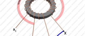
The windings are usually made concentric (one above the other), or alternating (as in the first experiment of Michael Faraday in 1831), sometimes called disk windings. In the latter case, a fairly large number of them can be wound through one, alternately: now high voltage, now low. Pure electrical copper (99.95%) with a resistivity of 17.24 - 17.54 nOhm m is used. Due to the high cost of the metal, refined aluminum is used for the manufacture of toroidal transformers of low and medium power. For other cases, restrictions on conductivity and plasticity affect.
In powerful transformers, the copper wire is of rectangular cross-section. This is done to save space. The core must be thick, allowing significant current to pass through, so as not to melt; a round cross-section will lead to excessive growth in size. The gain in uniformity of field distribution over the material would be reduced to zero. A thick rectangular wire is quite convenient to lay, which cannot be said about a thin one. Otherwise (according to design features), winding is carried out in exactly the same ways as in the case of a conventional transformer. Coils are made cylindrical, screw, single-layer, multi-layer.
Typical parameter calculation
Quite often, radio amateurs use a simplified method when calculating a transformer. It allows you to perform calculations at home without using quantities that are difficult to know. But it’s easier to use an online calculator ready for calculating a transformer. In order to use such a calculator, you will need to know some data, namely:
- voltage of the primary and secondary windings;
- core dimensions;
- plate thickness.
After entering them, you will need to click the “Calculate” button or something similar in name and wait for the result.
Rod type magnetic core
If it is not possible to calculate on a calculator, performing such an operation yourself is not difficult and manually. To do this, you will need to determine the voltage at the output of the secondary winding U2 and the required power Po. The calculation proceeds as follows:
- The load current is calculated: In=Po/U2, A.
- The value of the secondary winding current is calculated: I2 = 1.5*In, A.
- The power of the secondary winding is determined: P2 = U2*I2, W.
- The total power of the device is found: Pt = 1.25*P2, W.
- The current strength of the primary winding is calculated: I1 = Pt/U1, A.
- The required cross-section of the magnetic circuit is found: S = 1.3*√ Pt, cm².
It should be noted that if a device is designed with several terminals in the secondary winding, then in the fourth point all powers are summed up and their result is substituted instead of P2.
After the first stage is completed, proceed to the next stage of calculation. The number of turns in the primary winding is determined by the formula: K1 = 50*U1/S. And the number of turns of the secondary winding is determined by the expression K2= 55* U2/S, where:
- U1 - voltage of the primary winding, V.
- S—core area, cm².
- K1, K2 - number of turns in windings, pcs.
It remains to calculate the diameter of the wound wire. It is equal to D = 0.632*√ I, where:
- d — wire diameter, mm.
- I is the winding current of the calculated coil, A.
When selecting a magnetic core, you should maintain a ratio of 1 to 2 of the width of the core to its thickness. At the end of the calculation, the fillability is checked, i.e. whether the winding will fit on the frame. To do this, the window area is calculated using the formula: So = 50*Pt, mm2.
Autotransformer Features
Autotransformers are calculated similarly to simple transformers, only the core is determined not for the entire power, but for the power of the voltage difference.
For example, the power of the magnetic circuit is 250 W, the input is 220 volts, and the output needs to be 240 volts. The voltage difference is 20 V, with a power of 250 W the current will be 12.5 A. This current value corresponds to a power of 12.5 * 240 = 3000 W. The mains current consumption is 12.5+250/220=13.64A, which exactly corresponds to 3000W=220V*13.64A. The transformer has one 240 V winding with a 220 V tap, which is connected to the network. The section between the outlet and the outlet is wound with a wire rated at 12.5A.
Thus, an autotransformer allows you to obtain significantly more output power than a transformer with the same core with a low transmission coefficient.
Toroidal type transformer
Toroidal transformers have a number of advantages over other types: smaller size, lighter weight and, at the same time, higher efficiency. At the same time, they are easily wound and rewound. Using an online calculator to calculate a toroidal transformer allows you not only to reduce the manufacturing time of the product, but also to experiment on the fly with different input data. The following data is used:
- input winding voltage, V;
- output winding voltage, V;
- output winding current, A;
- outer diameter of the torus, mm;
- internal diameter of the torus, mm;
- torus height, mm.
It should be noted that almost all online programs do not demonstrate particular accuracy when calculating pulse transformers. To obtain high accuracy, you can use specially developed programs, for example, Lite-CalcIT, or calculate manually. For independent calculations, use the following formulas:
- Output winding power: P2=I2*U2, W.
- Overall power: Pg=P2/Q, W. Where Q is the coefficient taken from the reference book (0.76−0.96).
- The actual cross-section of the “iron” at the location of the coil: Sch= ((Dd)*h)/2, mm2.
- Calculated cross-section of the “iron” at the location of the coil: Sw =√Pq/1.2, mm2
- Torus window area: Sfh=d*s* π/4, mm2.
- The value of the operating current of the input winding: I1=P2/(U1*Q*cosφ), A, where cosφ is a reference value (from 0.85 to 0.94).
- The wire cross-section is found separately for each winding from the expression: Sp = I/J, mm2., where J is the current density taken from the reference book (from 3 to 5).
- The number of turns in the windings is calculated separately for each coil: Wn=45*Un*(1-Y/100)/Bm* Sch pcs., where Y is a table value that depends on the total power of the output windings.
- It remains to find the output power and the calculation of the toroidal power transformer is considered completed. Pout = Bm*J*Kok*Kct* Sch* Sfh /0.901, where: Bm - magnetic induction, Kok - wire filling coefficient, Kct - iron filling coefficient.
All coefficient values are taken from the radio equipment reference book (REA). Thus, it is not difficult to carry out calculations manually, but you will need accuracy and access to reference data, so it is much easier to use online services.
Definition of Toroidal Transformer Design
For those interested in the issue, we recommend studying the book by S.V. Kotenev, A.N. Evseev on calculating the optimization of toroidal transformers (Hot Line - Telecom publication, 2011). We remind you: the publication is protected by copyright law. Professionals will find the strength (means) to purchase a book if necessary. According to the chapters, the calculation begins by determining the idle speed parameters. It describes in detail how to find active and reactive currents and calculate key parameters.
The printed publication, despite some controversial presentation, simultaneously makes it clear why a transformer connected to the circuit, without a load, does not burn out (the current energy is consumed by magnetization). Although it would seem that the obvious outcome of the event was predicted.
The number of turns of the primary winding is selected from the condition that the magnetic induction does not exceed the maximum value (before entering the saturation mode, where the value does not change with increasing field strength). If the design is carried out for a 230 volt household network, a tolerance is taken in accordance with GOST 13109. In our case, this means an amplitude deviation within 10%. We remember: the entire industry switched to 230 volts in the 21st century (220 is not used, it is cited in the literature as a “legacy of a difficult past”).
The devil is in the details
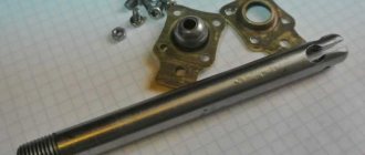
It is precisely in the case of asymmetrical transformers that the “zero” turn cannot be short-circuited. And since neither in nature nor in electronics are there two absolutely identical creatures, this rule must always be observed. It would seem - where does it even come from, this coil, and even one common for two transformers? This could be, for example, an axis on which both tori are “strung”, which together with the body forms a short-circuited coil. A very convenient design solution, and it can be used, you just need to break the chain by insulating one of the ends of the axis, for example, as in the picture:
Insulating washers made of fiberglass are placed under the nuts, and a PVC tube is put on the axis itself, where it passes through the aluminum corner.
Recommendations from experts
When the master has carefully studied the method of making a transformer with his own hands, he can safely proceed to the practical part. Since winding turns is considered a very complex process, you will need to be patient so that the final result meets all expectations. After all, the performance characteristics of the device depend on how well this stage is performed.
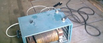
To simplify this task, you can use a special machine designed for winding toroidal transformers. The price of such a unit is considered affordable, and if desired, you can make it yourself.
Short description
Modern manufacturers are engaged in the industrial production of several types of magnetic cores for transformers - armored, rod, toroidal. If we compare their operational characteristics and areas of use, then the latter option can be considered more effective. The thing is that such a device has extremely positive parameters , due to which it is actively used in modern industry.
High performance and long service life have led to the fact that now the toroidal transformer is a basic element in lighting technology, voltage stabilizers, uninterruptible power supplies, radio engineering, as well as medical and diagnostic equipment.
The manufacturers themselves claim that such a unit is presented in the form of a single-phase installation, which can both reduce and increase power. For high-quality operation, the transformer is equipped with a powerful core with two or more windings. But the principle of its operation is no different from those models that are equipped with armor or rod winding.
Regardless of its operational characteristics, a transformer is a device whose main task is based on converting electricity from one quantity to another. However, even the most minimal changes in design can significantly change the final size and weight of the electrical installation. Thanks to this, technical and economic parameters will only increase.
External links [edit]
- Inductor and Transformer Design Guides - Magnets
- The approximate toroid inductance includes the formula but assumes a circular winding
- Design features of toroidal transformers Material for industrial research: Design of ferrite toroidal transformers
| vte Transformer themes | ||
| Themes |
| |
| Types |
| |
| Reels |
| |
| Manufacturers |
|