Despite the variety of electrical equipment on the market, not in all situations it is possible to find a suitable converter unit to solve a specific problem. Therefore, many ordinary people try to make a transformer with their own hands to obtain certain operating parameters. It is worth noting that anyone can wind a transformer, even without specialized equipment and special skills, but this process is quite labor-intensive and painstaking. Therefore, initially you will have to decide on the type and characteristics of the device.
What power will it have?
Once you can answer each of the questions listed, purchase the required materials. You can easily buy the necessary materials in specialized stores. You will need wires, premium quality tape insulation, and a core.
The transformer itself requires winding. For these purposes, a machine should be created, the manufacture of which is carried out from a board forty centimeters long and ten centimeters wide. Several bars need to be attached to the board using screws.
The distance between the bars should not be less than thirty centimeters. Then you should drill holes eight millimeters in diameter. In the created holes you need to insert special rods for the device’s coil.
A thread should be created on one side. By tightening the equipped washer, you will get its handle. The dimensions of the winding machine can be chosen at your own discretion. First of all, the right choice directly depends on the size of the core. With its ring-shaped form, the winding is created manually.
According to the diagram of the transformer device, the device can be equipped with a varied number of turns. The required quantity is calculated based on power. For example, if it is necessary to create a device up to 220 volts, the power should reach at least 150 watts.
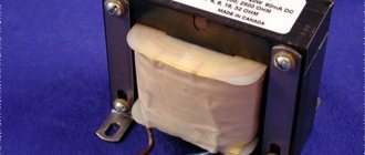
The shape of the magnetic wire should be O-shaped. You can make it out of a used TV. In this case, the cross section is determined using a certain formula.
Self-production
The design of the transformer is quite simple, so it is not difficult to make it yourself. But before proceeding directly to its manufacture, it is necessary not only to prepare the material and tools, but also to perform a preliminary calculation.
How to make a step-down transformer with your own hands can be considered using a specific example. Let the task be to manufacture a converter from 220 V to 12 V with an output current of 10 A.
It is unlikely that you can make the core yourself, so it is better to use an unnecessary transformer of any type. You will need to carefully disassemble it and remove the “hardware” from there.
The next step is to make the frame. You can use various materials, for example, fiberglass. To calculate it, you can use the Power Trans program. It is worth noting that although this application can also calculate the number of turns, it is better not to use it for these purposes, due to not entirely correct results.
In the program, you can select the type of core, as well as set the cross-section of the core, windows and power of the product. Then click on calculation and get a finished drawing with dimensions. Next, all that remains is to transfer the drawing onto the textolite and cut out the required number of parts. After all the elements are prepared they are assembled into a frame.
Now you can proceed to preparing the insulating gaskets. They will be necessary to isolate the layers from each other. They are cut into strips of varnished fabric, fluoroplastic, mylar, or even thick paper, for example, which is used for baking. It is important to note that the width of the strip is made a couple of millimeters larger, and it is not recommended to mark the cutting lines with a graphite pencil (graphite conducts current).
At the last stage, the wire is prepared. Since it will be necessary to wind a 220 V 12 V 10a transformer, that is, a step-down transformer, the secondary coil will be made with a thick wire, and the primary coil with a thin wire.
Design calculation
Design calculations begin by finding the power that the secondary winding must withstand. Substituting into the formula: P = U * I, the values given to the conditions b for the secondary coil, you get: P 2 = 12 * 10 = 120 W. Assuming that the efficiency of the product will be about 80% (the average value for all transformers), we can determine the primary power: P = P 2/0.8 = 120/0.8 = 150 W.
Based on the fact that power is transmitted through the core, the value of P1 will depend on the cross-section of the magnetic circuit. The cross section of the core is found from the expression: S = (P 1)½ = 150 = 12.2 cm2. Now you can find the required number of turns in the primary winding to produce one volt: W = 50/ S = 4.1. That is, for a voltage of 220 volts you will need to wind 917 turns, and for a secondary voltage - 48 turns.
You might be interested in: Electrician safety precautions when working with electricity
The current flowing through the primary coil will be equal to: I = P / U = 150/220 = 0.68 A. Hence the diameter of the primary winding wire is calculated by the formula: d = 0.8 * (I)½ will be 0.66 mm, and for the secondary - 2.5 mm. The cross-sectional area can be taken from reference tables or calculated using the formula: S = 0.8 * d 2. It will be 0.3 mm2 and 5 mm2, respectively.
If suddenly a wire of such a cross-section is difficult to get, then you can use several conductors connected to each other in parallel. In this case, their total cross-sectional area should be slightly larger than the calculated one.
Winding technique
To wind the product, the made frame must be clamped on the axis and centered . It is better to first wrap the wire around some cylindrical object. For example, a spool of thread or a piece of pipe. A coil of wire is placed opposite the clamped frame. The wire is placed on the base and made several turns around it. Then they begin to rotate the frame body. In this case, you should carefully ensure that each turn lies next to the other and does not intersect it. After each layer, two turns of insulation are applied.
Once the primary winding is wound, the wire must be brought out to the side to form a lead. The rest of the wire is cut off. Before applying the secondary winding, several layers of insulation are laid and the whole process is repeated, but with a wire of a thicker cross-section. Upon completion of the work, the free ends of the coils are soldered to the terminals. Using a tester, the coils are checked for breaking.
There are some nuances when winding that it is advisable to know. During winding, the wire may accidentally break. In this case, you will need to strip the broken ends, twist them and solder them. Carefully insulate the soldering area, for example, by placing two layers of insulating paper. When winding, to increase the electrical strength of the product, it is recommended to impregnate each layer. This prevents vibration of the wire. Epoxy or acrylic based varnishes are used as impregnation.
Now all that remains is to connect the transformer from 220 to 12 to the power source. The connection to it occurs in a parallel circuit. Using a multimeter you can check the output voltage. To do this, it switches to the AC signal measurement mode.
If in the future it is necessary to obtain a constant signal, then a diode bridge (rectifier) with an electrolytic capacitor (smoothing filter) is connected to the secondary winding of the transformer. But it should be taken into account that for a current of 10 amperes you will need a corresponding rectifier unit capable of withstanding such a current with a margin of about 15%.
Thus, even a novice radio amateur can make a step-down transformer on his own. The main thing is to perform the correct calculation. And the manufactured product will certainly find its application.
Arrangement of the reel housing
The body is made of high-quality cardboard paper. Its inner side is slightly larger compared to the core part of the core. When using an O-shaped core, several coils will be required. With a w-shaped core, it is enough to use only one coil.
When using a round core, it should be wrapped using insulation. Then you can carry out wire winding. Once you are done with the primary winding, it should be covered with several insulating layers. After this you need to wind the next layer. The ends of the existing windings are brought out to the outside.
When using magnetic wire, the transformer body is assembled step by step:
- A certain size of sleeve with the required cuffs is cut out.
- Cardboard cheeks are created.
- The main part of the coil is rolled up into a special box.
- Cheeks are placed on the sleeves.
Clarification of a number of technical parameters
However, before starting the practical part, you will need to give clear answers to a number of questions.
- How exactly should the future unit change the current: increase it or decrease it?
- What voltage will be supplied to the primary coil and removed from the secondary?
- What will be the operating frequency of this device?
- How much power should it have after assembly is completed?
Creating windings for a magnifying transformer
You should put the reel on a block of natural wood. It is necessary to drill a special hole in it for the winding rod.
One of the serious stages involves connecting the current. The part is inserted inside the machine and winding can be done:
- Varnished cloth is wound on top of the coil in several layers.
- The end of the existing wire is fixed to the equipped cheek, after which you can begin to rotate the handle.
- The coils are laid as tightly as possible.
- After winding, you should cut the wire for subsequent fastening on top of the cheek near the first one.
- It is necessary to attach an insulating tube to the existing terminals.
Purchase of components and consumables
After the schematic diagram has been fully prepared, you can begin purchasing the parts and consumables needed for assembly.
Usually, the necessary materials and accessories, including varnished wire and terminals, are easy to find in the first radio store you come across.
First you need to buy
- Electrical tape or heat-resistant tape;
- Core configuration corresponding to the project;
- Insulated wires.
Assembling a magnifying transformer
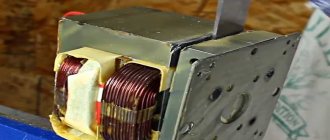
If you need to learn how to create a transformer yourself, use the instructions. To assemble the booster device, it is important to completely disassemble the core. When using separately placed plates, it is important to determine the batch thickness and calculate the sheets.
If noise is produced when the device is turned on, it is necessary to secure the existing fasteners as tightly as possible. Then you should check the device for functionality. For these purposes, it is connected to the network, after which a voltage of 12V should be displayed.
It is important to know that when turning on the device, it is important to leave it running for a couple of hours. In this case, the transformer must not overheat.
What is construction expertise?Selling a share in an apartment
- Certificate of conformity for equipment
Widest scope of application
The simplicity of assembly and high efficiency of transformers became the reason for their inclusion in the composition:
- Power supplies;
- TVs;
- Microwave ovens;
- Radio stations;
- Welding machines;
- Communication equipment;
- All kinds of automation
- Control and measuring equipment.
Tools
To make a transformer yourself, you should take tools, as well as certain materials:
- Lakotkan.
- A core for which a used TV is quite suitable.
- Thick cardboard paper.
- Boards and bars made of natural wood.
- Steel rod.
- Saw, special glue.
Making a transformer with your own hands, as in the photo, is not at all problematic. If you need to make a transformer designed for halogen light bulbs, then you can also use the tools listed above.
Do not forget that it is very important to adhere to the winding process. If you strictly follow the important rules, the device will serve you for more than a decade. These materials, as well as tools, will be enough for you to create a high-quality and practical transformer with your own hands.
Based on such a homemade product, you can create a transformer for recharging a machine battery, or create a step-up device for a laboratory power source, a wood burner, or another device that will satisfy the needs of a DIYer.
The benefits of a detailed drawing
After providing comprehensive answers to the above questions, a diagram of the transformer device can be drawn up on paper or on a computer. It is not superfluous to do this even with a clear understanding of all the parameters and features of the radio component.
Often a drawing allows you to significantly clarify
- Scheme of connecting and bringing out contact wires;
- Number of plates in the W-shaped core;
- Method of arrangement of primary and secondary coils.
Effect of power on the number of turns
A transformer made by yourself can be equipped with any number of turns.
The instructions on how to make a transformer indicate that the required number of turns is calculated based on the power of the intended device.
A guarantee of durability and reliability
In general, the winding and assembly process does not cause much difficulty. This method can produce devices for a range of applications, including halogen lamps.
In order for the result of all the efforts made to be a unit that is actually suitable for use, the winding technique described above must be carefully followed. This will guarantee not only the serviceability of the transformer, but also its uninterrupted operation for a very long time.
Winding wire and applying insulation
If a round core was chosen as the base, then it should first be wrapped with electrical tape. Next you can start winding the wire.
- After the application of the primary winding is completed, it is covered with dense insulation.
- Then it’s time to wrap the second layer.
- The ends of the windings are brought out, and contacts are soldered to them for interfacing with other equipment.
How to wind?
The core is covered with tape 5 times, the wire is placed in the groove, and winding-1 is wound. Both ends should be brought out to one side and insulated with Teflon tape or cambric. To fix the last turn, you can use regular thread, so it will not unwind.
4-5 circles of tape are laid on top of this, the rod is placed in the body of a syringe 3 cm long. It is also wrapped with tape twice and a secondary winding is performed, the width is one and a half centimeters. Each layer is insulated with tape or double fluoroplastic tape. The ends are brought out on different sides, three conclusions are made from one, and one from the second.
All this is again insulated with adhesive tape in five layers, flexible wires for output are soldered to it, and insulated again.
If a break occurs somewhere, the place is cleaned, twisted, soldered, isolated. Therefore, you can use the old wire, as long as it is properly soldered. To increase electrical strength, each layer of winding is impregnated with acrylic varnish or epoxy.
The turns are placed as close to each other as possible, parallel to the core if possible.
Computing application for Android
Mathematical expressions that can be found in specialized literature will provide reliable assistance in clarifying a number of parameters. Almost all of these formulas have already been included in computer programs, which in most cases makes it possible to minimize the calculation part.
You just need to specify some data about the future device in the program interface, and the smartphone application will display a comprehensive table with the requested information.
Code for microcontroller
Since in my case it was enough to detect the fact that the load was turned on, the code turned out to be very simple:
int measureCurrent(){ int i; const int cnt = 10; int minv = 1025; int maxv = -1; for(i = 0; i < cnt; i++) { int value = analogRead(A0); if (value > maxv) { maxv = value; } if (value < minv) { minv = value; } delay(2); } return maxv - minv; }
During one oscillation period, the maximum and minimum values on the ADC are measured and the current value is determined by the difference between them. When the pump is turned on, the function returns a value of more than 200 counts, and when it is turned off, it returns less than 10.
Graph of measureCurrent() function values versus time
Conclusion
The result was a fairly simple, reliable and cheap system for detecting submersible pump starts. It has been working continuously for 7 months and has not yet required any intervention.
Making your own current transformer turned out to be quite easy and quite interesting. I have tried to present the experience gained here in as much detail as possible. I hope this article will allow someone to quickly understand the operating principles of a current transformer and implement their own projects using this element.
UPD: The comments suggested a very cheap version of a ready-made current transformer - ZMCT103C, judging by its characteristics it could well be used to solve my problem.