When welding critical structures, much attention is paid to the leg of the weld. In factories and enterprises, this parameter is checked separately and the product may be considered unsuitable and sent for rework, which will entail loss of time and financial costs. Here we will look at what a seam leg is, how to correctly calculate and check it.
The leg of a seam is the two sides of a triangle diverging from a right angle. In fact, the leg here has the same definition as in school geometry. Ideally, such a triangle would be isosceles, then the same part of the deposited metal would fall on each side. This ensures the best part retention and joint strength.
The concept of weld leg is applicable to all types of welding. A certain leg can be achieved when connecting using a coated consumable electrode (MMA), a semi-automatic torch (MIG/MAG), a non-consumable tungsten rod and an argon welding torch (TIG). Since there are always two legs in a corner and T-joint (on the vertical and lower surface of the workpiece), when measuring, for convenience, they are sometimes designated as K1 and K2. In a good seam, K1 and K2 are equal.
Leg selection
The surface of the weld seam at corner joints is:
- Convex - the roller protrudes outward, sometimes exceeding the length of the leg itself. Externally, such a weld looks powerful, but an increased amount of deposited metal leads to the formation of internal stresses. Because of this, the product is prone to deformation, especially if its walls are 2-3 mm.
- Concave - the surface of the seam is curved inward and located below the height of the leg. To achieve this shape, you need to increase the current and move the electrode or torch faster. On a semi-automatic machine, it is worth increasing the inductance so that the drop separation process becomes smoother. This increases the penetration depth and promotes a concave weld surface.
- Flat - between the sides of the corner joint there is an almost flat, oblique plane of the seam surface. This happens less often, but is still possible. This option is more convenient for mechanical processing of joints - it is not enough to clean off the deposited metal and the grinding machine equipment immediately captures the entire surface.
In each case, the leg means the length (on the horizontal part of the workpiece) and height (on the vertical part of the workpiece) of the side of the triangle, starting from the root of the seam. In other words, this is the distance from the edge (outer border) of the seam to the surface of another part.
It seems that the more legs, the better, but this is not so. A large leg of the weld creates stress in the joint and leads to inversion of the structure. The heating area of the part increases. The product may lead to severe damage. A large leg always means excessive consumption of material (electrodes, welding or filler wire), and a time delay. Creating a high-height weld requires holding the arc in one place for a long time, which leads to burnout of alloying elements and faster corrosion. Therefore, the leg should be calculated correctly for each design.
How to measure
To check the quality of the work performed, it is necessary to measure its main parameters. Measurements are carried out using sets of specially calibrated plates - cathetometers. They are applied alternately perpendicular to the line of suture material until a complete fit is achieved.
Cathetometer
If a cathetometer is not at hand, measurements can be made using a caliper and a square. The square is applied to one of the parts so that its top rests against the top of the welding bead. The caliper probe is lowered from behind the square to the other top of the roller. The reach of the probe will be equal to the desired length.
The accuracy of such measurements will be somewhat lower, and it will take much more time to check the welded joint, especially a long one.
Calculation of the seam leg
Since a fillet weld is similar in cross-section to a triangle, you can find out the height and length of its sides using a geometric formula, using mathematical abilities. The calculation is made using the formula:
T=S*cos45º
The given components are deciphered as follows:
T is the size of the seam leg that we are trying to calculate
S - width of the roller (in geometry - the hypotenuse of the triangle)
cos45º is a standard value with a coefficient of 0.7
Let's calculate the leg of the weld in practice. For example, we have a corner connection with a bead width of 5 mm. We substitute this value into the formula and get 5*0.7=3.5 mm. This means the leg of the seam is 3.5 mm. This formula is applicable when the weld metal lies evenly on each side of the fillet joint.
The optimal parameters of the welding seam for each metal thickness were established experimentally. If you adhere to them, you will get a strong connection without wasting filler material. We present the characteristics of the weld in the table.
| Workpiece thickness, mm | Connection type | Minimum seam leg, mm |
| 4-5 | T-bar with double-sided penetration | 4 |
| 6-10 | T-bar with double-sided penetration | 4-5 |
| 11-16 | T-bar with double-sided penetration | 4-6 |
| 17-22 | T-bar with double-sided penetration | 5-7 |
| 23-32 | T-bar with double-sided penetration | 6-8 |
| 4-5 | T-shaped with one-sided penetration or corner with one-sided penetration | 5 |
| 6-10 | T-shaped with one-sided penetration or corner with one-sided penetration | 6 |
| 11-16 | T-shaped with one-sided penetration or corner with one-sided penetration | 7 |
| 17-22 | T-shaped with one-sided penetration or corner with one-sided penetration | 8 |
| 23-32 | T-shaped with one-sided penetration or corner with one-sided penetration | 9 |
As you can see, the size of the leg ranges from 30 to 100% of the thickness of the part - the thinner the workpiece, the closer the size of the leg is to its cross-section. When welding parts with different thicknesses, the leg is selected according to the larger indicator. For example, if you are welding workpieces with a cross-section of 5 and 10 mm with penetration on only one side, the leg of the weld should be 6 mm (taken from the calculation as if two sides were 10 mm thick). If you focus on the thin side, you will get weak reinforcement on thick metal and the connection will be unreliable. But in this case, it is important to choose the right amperage and cook with a certain arc technique.
Main types of fillet welds
Figure 529.2 . Main types of welded joints with fillet welds.
a) Frontal seams (2) when joining with an overlap;
b) Flank seams (3) when joining with an overlap;
c) Frontal and flank seams when joining butt joints with overlays (4);
d) Fillet welds when connecting v-tees (butt-to-end) without cutting and with cutting edges;
e) Shear plane (shear) of the flank seam
2.1. Geometric characteristics of fillet welds
One of the main geometric characteristics of a fillet weld, along with the seam length lw , is the seam leg kf . This is due to the fact that no matter what stress-strain state the structural element in question is in, tangential stresses will always act on one of the weld legs. And since shear (shear) resistance is always less than tensile or compression resistance, Table 530.2 considers only one type of stress-strain state - conditional shear.
In this regard, determining the weld leg when calculating fillet welds becomes of great importance. Figure 529.2.e) shows possible geometric shapes of fillet welds (sectional view). As can be seen from this figure, the smallest possible value is taken as the calculated value of the weld leg.
In addition, it is assumed that the destruction of the weld material can occur not along one of the legs, but in a section inclined to the legs at a certain angle or along the fusion boundary. Therefore, when calculating fillet welds, two sections are considered: along the weld metal (1) and along the fusion boundary (2):
Figure 529.3 . Design sections of fillet welds
Accordingly, to determine one of the dimensions of the section under consideration, the coefficients βf - when calculating along the weld metal and βz - when calculating along the fusion boundary. The value of these coefficients can be determined using the following table:
Table 529.1 (according to SP 16.13330.2011 “Steel structures”). Values of coefficients βf and βz for fillet welds
Note : In SNiP II-23-81* “Steel Structures” and in old reference books, the wording of the last paragraph (type of welding) was slightly different, namely: “Manual; semi-automatic (mechanized)…” and so on, which made it possible to easily determine the values of the coefficients for manual welding. Now the wording contains the conjunction “and”, which in my opinion is not entirely correct, since it allows us to consider further conditions as relating to both definitions. In addition, in the indicated sources, the values of the coefficients for manual welding were determined regardless of the position of the weld. Now we see a strange division that allows us to determine only βf when welding in a boat or βz for all other weld positions. In my opinion, this is a clear mistake by the editor, however, SP 16.13330.2011 “Steel Structures” is an updated version of the now defunct SNiP II-23-81* “Steel Structures” and when making calculations, one should be guided by the provisions of the SP. But I’ll still give the corresponding table from the old SNiP:
Consequences of incorrect leg calculations
We have already considered the negative consequences of a large leg. The second common mistake is that the seam leg is too small. Then there is little deposited metal on the sides, which reduces the strength of the connection. If it breaks or vibrates, the structure may not withstand the load and the seam will crack. Although the small leg saves consumables, it is only acceptable for non-essential connections (barbecue, table, etc.).
Another mistake welders make is an asymmetrical leg. Most often, the bottom flange of the seam is too wide, and the top flange is too short. This happens when the technique is incorrect or the welding mode is selected, because the molten metal flows down under the influence of gravity. The seam looks wide, but only slightly extends to the vertical side, so it holds weakly and is not designed for serious loads.
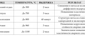
Welding zones
The fusion zone with partially melted grains is 0.1−0.4 mm of the main metal. When the metal in this zone warms up, its structure becomes needle-like with high fragility and low strength.
The thermal zone is divided into four sections:
- I - refers to the base metal heated to a temperature exceeding 1100 °C. The structure of this area is coarse-grained, and the grains in this area are approximately 12 times larger than standard. Due to overheating, the viscosity, ductility and other mechanical properties of the metal decrease, and rupture often occurs in the weakest area of the weld.
- II - section is the normalization zone, in which the main metal is heated to 900 °C. The grain structure here is much finer than in the previous case. This area occupies 1−4 mm.
- III - zone of incomplete crystallization, in which the main metal is heated to 750−900 °C. Both small and large grains are found here. Mechanical properties are reduced due to the uneven distribution of crystals.
- IV—recrystallization zone. It warms up to 450−750 °C and restores the shape of grains deformed due to past mechanical influences. Approximate width - 5−7 mm.
What affects the weld leg
The formation of the weld leg of corner and T joints is influenced by a number of factors:
- Directionality of the torch or electrode.
If you weld fillet welds while holding the electrode or torch at an angle of 45º, then the liquid metal will flow down to the bottom shelf under the influence of gravity, lowering the vertical leg. Experienced welders in this case change the angle by 20-30º, directing the end of the electrode to a vertical surface. This is how you can change the height of the leg and achieve an equilateral triangle in the cross-section of the seam. - Position of the product in space.
It is easier to obtain a uniform seam on a corner joint by placing the product “in a boat”. Then the surface of the weld pool is smooth, the metal does not flow anywhere and covers both sides being joined equally.
- Arc speed.
When carried out quickly, the seam turns out to be narrow, and the leg is often small. Welding with a delay leads to an increase in the height of the seam and the growth of the leg. The welding speed must be selected on the rough workpiece, having tried different options, and only then move on to welding the critical product.
- Current strength.
Low current strength facilitates the application of filler metal from above, without deep penetration. The leg turns out to be large, but the quality of the connection is poor. Too high a welding current leads to deep penetration, but increases the fluidity of the metal and promotes undercuts on the vertical side, which is also a defect.
- Inductance.
Determines the transfer rate of a drop of molten metal during semi-automatic welding. The correct settings help to warm up the part well, apply a neat seam, and reduce spattering.
- Characteristics of filler metal.
If the core of a consumable electrode or the wire of a semi-automatic machine has high-temperature additives, then the weld pool becomes thicker, which leads to the growth of the leg. Low-temperature alloys flow faster, reducing the height of the weld leg.
Welded joints, their advantages and disadvantages
Welding connection is one of the types of permanent connections of parts.
It is performed by intensely heating the joints to a temperature capable of melting parts or bringing the metal to a plastic state. This creates a molecular cohesive force that can hold different elements together.
The advantages include the high strength and reliability of such connections.
Disadvantages of welded joints:
- the presence of residual stress due to non-uniform heating and cooling of the parts being welded;
- warping of parts;
- the presence of hidden flaws in the form of cracks and lack of penetration, which reduce strength.