Metal structures welded from metal are in demand in various spheres of life. However, during welding work, various types of weld defects may occur. They shorten the possible service life of the connection and reduce the safety level of the finished product.
Types of weld defects
All tolerances on weld dimensions are regulated by GOST requirements for each type of welding. Any deviations of the readings from the approved standards are considered to be defects. They can be a consequence of errors in the process of both preparation and execution of welding work.
Most defects in a welded joint have a negative impact on its strength characteristics. All defects are divided into three groups:
- external _ The main indicators are irregular joint shape, cracks, sagging, craters, seam undercuts, burns and other visual signs that can be detected on the surface. They are visible upon careful visual inspection and only a few can be noticed at first glance;
- internal . Defects are incomplete or uneven fusion of metals, cracks or porosity in the structure, the presence of foreign inclusions - slag, oxide, non-metallic impurities; other flaws located inside the seam;
- end-to- end Cracks, undercuts, burns and other damage that are end-to-end and visible on both sides.
Any defects are grounds for rejection of the work and must be corrected. This rule is especially relevant for supporting metal structures - frames, frames, sheathing, etc. They must be welded flawlessly to withstand the expected loads. Otherwise, the structures may become a source of danger to others.
Devices for detecting pipeline damage
Extended corrosion damage to heating mains occurs due to the gradual filling of thermal chambers and channels with water. Detection of pipeline damage in heating networks is carried out using acoustic and correlation leak detectors. The essence of the search is to determine the location of the water leak by recording sound signals with a vibration sensor, which tracks the release of water along the controlled area. The violation coordinates are determined by the maximum value of the sound signal in a given frequency range. The correlation method involves the use of two vibration sensors located at a distance of several hundred meters from each other. The installation points of the device are determined by the staffing schedule.
The portable pipeline damage detector, brand DPP A, is designed to find points where the insulation of old and under construction gas networks has been damaged without excavating a pit under any type of road surface. Used to establish the location of pipes, power electrical cables. The maximum radius of action when searching for an existing pipeline is 500 m, for a newly constructed pipeline – 2 km.
The device allows only periodic monitoring. It records the nature of the voltage change along the path when current passes through the circuit: local oscillator - pipe - ground - local oscillator. The direction of the route and its depth are established based on the induction method.
The device is powered by a 9 V battery. It is connected to the UEC equipment at control points provided for by the project. The length of the tested section is 6 km, electrical protection class is II, current strength is 1.5 mA. The device can be operated at outdoor temperatures in the range - from -45 to +45°C and humidity - 45-75%.
The reliability of gas, water, and heat supply systems depends on the timely identification of the causes of damage to pipelines and the elimination of their consequences. It is laid at the stage of design, installation and during operation. To achieve this, parallel lines of distribution systems are constructed and looped sections of the network are created.
Classification of defects in welded joints
Not in every case is it possible to achieve ideal quality of the welded joint. If desired, you can find deviations from the established requirements. The full classification of welded joints is set out in paragraphs of GOST 30242-97. The document contains information about all possible flaws. Of these, we can highlight some that are most often encountered during control inspection of connecting joints.
Cracks
Cracks have the greatest negative impact on the quality of the weld. Potentially, they are the most dangerous, since they can cause rapid destruction of the entire structure, which in turn can lead to tragedy.
Cracks appear for various reasons:
- the joints are positioned incorrectly;
- the welding site was sharply cooled;
- incorrectly selected consumables;
- the metal crystallized due to excessively high temperature.
Based on the method of formation, cracks can be longitudinal, transverse or radial, and based on size, it is customary to distinguish between macro- and microcracks. Regardless of the type, causes and method of formation, a crack is an unacceptable defect.
Undercuts
Visually, the flaw is a longitudinal depression on the outer part of the seam. Due to the undercut, the cross-section of the seam is reduced and internal joint stress is generated. The strength of such a seam is highly questionable. The main reason for the formation of a defect is an overestimated welding current. Most often, undercuts are characteristic of horizontal seams.
Surges
Excess melt flows onto the surface of the workpiece, cools and forms a false bead. This is an influx that does not have strong fusion with the working surface. Most often, a defect is formed during horizontal welding of butt or fillet welds. The reason for their formation is insufficient heating of the base metal, due to excess filler material or scale on the edges of the mating surfaces.
Burns
A flaw is a through hole that is formed due to metal leaking out of the weld pool. As a rule, an influx forms from the reverse side. Burn-through is caused by too slow movement of the electrode along the joint line, too much current, insufficient thickness of the gasket or its loose fit, or a large gap between the parts.
Lack of penetration
If there are areas between the seams and the base metal where lack of fusion between them is visible, then this is a lack of fusion. That is, the base metal did not warm up properly to form a single whole with the melt. Such a defect greatly reduces the strength characteristics of the connection and the entire structure as a whole. The reason for lack of penetration may be too high a speed of movement of the electrode, poor preliminary preparation of the edges, the presence of scale, rust and other contaminants on the surface of the workpieces being joined.
Craters
Small depressions in the weld bead are formed as a result of a break in the welding arc. Defects lead to a reduction in the cross-section of the joint, which reduces its strength. The secondary danger of the crater is that its bottom may have additional loose inclusions, leading to the appearance of cracks.
Fistulas
Flaws are surface defects in the form of cavities. They reduce the strength of the joint and are additionally dangerous because they can provoke the formation of cracks. Fistulas are characterized by an arbitrary shape and can form both on the outside and on the inside.
Pores in the weld
Gas-filled pores may form during the welding process. The reason for their occurrence is various contaminants on the surface of the workpiece, high speed of electrode movement, and too high carbon content in the filler material.
Foreign inclusions
The quality of the weld is significantly reduced due to foreign inclusions - slag, flux, oxide, tungsten and others. The main reason that causes them is an incorrectly selected welding mode.
What is called a burn-through?
The defect occurs due to the leakage of weld pool metal through a hole in the seam formed as a result of through penetration. Sagging appears on the reverse side.
Reasons leading to burns:
- insufficient welding speed;
- increased power of the welding flame;
- loose connection of the lining to the main metal and its insufficient thickness;
- excessive welding current;
- increased gap between edges;
- power supply stop;
- welder's carelessness.
Causes of weld defects
Any defect is formed due to a certain factor. There are different reasons for the formation of weld defects:
- During the work, low-quality consumables were used;
- the technology for performing welding work was not followed;
- low quality metal used to create the welded structure;
- equipment malfunction or poor quality work;
- incorrectly selected welding mode;
- technological errors were made due to the low qualifications of the specialist.
To obtain a high-quality metal structure, strict adherence to technological parameters and welding standards is required, and specialists with a sufficient level of qualification are involved in the work.
Group 2. Pores
200 A Gas cavityen gas cavity
fr soufflure
A cavity of arbitrary shape formed by gases trapped in molten metal, which has no corners 2011 Aa Gas poreen gas pore
fr soufflure spheroidale
Gas cavity is usually spherical 2012 Uniformly distributed porosityen uniformly distributed porosity
fr souflures spheroidales
A group of gas pores distributed evenly in the weld metal. Should be distinguished from chain of pores (2014) 2013 Cluster of poresen localized (clustered)
fr nid de soufflures
A group of gas cavities (three or more), arranged in a cluster with a distance between them of less than three maximum sizes of the largest of the cavities 2014 Chain of poresen linear porosity
fr soufflures allignees
(ou en chapelet)
A series of gas pores arranged in a line, usually parallel to the axis of the weld, with a distance between them of less than three maximum dimensions of the largest of the pores 2015 A b Oblong cavityen elongated cavity
fr soufflure allongee
A discontinuity extended along the axis of the weld. The length of the discontinuity is at least twice the height 2016 Ab Fistulaen worm-hole
fr soufflure vermiculaire
A tubular cavity in the weld metal caused by the release of gas. The shape and position of the fistula are determined by the hardening mode and the gas source. Typically, fistulas are grouped into clusters and distributed in a herringbone pattern 2017 Superficial poreen surface pore
fr picure
Gas pore that breaks the continuity of the surface of the weld 202 R Shrinkage cavityen shrinkage
fr retassure
Cavity formed due to shrinkage during solidification 2024 K Crateren crater pipe
fr retassure de cratere
Shrinkage cavity at the end of the weld bead, not welded before or during subsequent passesDefect detection methods
Various methods are used to identify weld defects:
- joint measurements and visual inspection;
- checking connections for leaks;
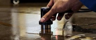
- searching for defects using special instruments;
- laboratory tests of samples for strength.
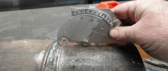
Visual determination of the quality of the weld is carried out only after thoroughly cleaning its surface from slag, eliminating various contaminants and frozen metal spatters. The dimensions, shape, and presence of defects are checked - burns, fistulas, cracks, craters and other flaws.
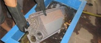
Thanks to leakage tests, it is possible to determine the presence or absence of pipeline defects - pores, cracks, lack of fusion. The tightness of the structure is checked in the following ways:
- air blowing;
- filling with water under pressure;
- kerosene treatment.
If a defect is detected, additional processing is required to eliminate it.
Group 1. Cracks
100 E Cracksen cracks
fr fissures
Discontinuity caused by local rupture of a weld, which may occur as a result of cooling or loads 1001 Microcracken microfissure (microcrack)
fr microfissure
A crack having microscopic dimensions, which is detected by physical methods at no less than fifty-fold magnification 101 Ea Longitudinal cracken longitudinal crack
fr fissure longitudinale
A crack oriented parallel to the axis of the weld.It can be located:
1011 in weld metal; 1012 at the fusion boundary; 1013 in the heat affected zone; 1014 in base metal 102 Eb Transverse cracken transverse crack
fr fissure transversale
A crack oriented transverse to the axis of the weld. It can be located: 1021 in the weld metal; 1023 in the heat affected zone; 1024 in base metal 103 E Radial cracksen radiation cracks
fr fissures rayonnates
Cracks that radiate from one point. They can be: 1031 in the weld metal; 1033 in the heat affected zone; 1034 in base metalNote—Cracks of this type, diverging in different directions, are known as star cracks.
104 Ec Crack in the crateren crater cracks
fr fissure de cratere
A crack in the weld crater, which can be: 1045 longitudinal; 1046 transverse; 1047 star-shaped 105 E Separate cracksen group of disconnected cracks
fr reseau de fissures marbrees
A group of cracks that can be located: 1051 in the weld metal; 1053 in the heat affected zone; 1054 in the base metal 106 E Branched cracksen branching cracks
fr fissure ramifiees
A group of cracks arising from a single crack.They can be located:
1061 in weld metal; 1063 in the heat affected zone; 1064 in base metalMethods for eliminating defects in welded joints
Regardless of the equipment involved - inverter, classic device, transformer, etc. - the formation of defects is not excluded. It is customary to distinguish between so-called acceptable and unacceptable welding defects. Depending on the type and complexity of the defects, the suitability of the finished product for use is determined.
Designs that are not approved for use are sent for revision. How the defect will be eliminated depends on the type of defect:
- the burn is welded after thoroughly cleaning the welded joint;
- undercuts are eliminated by applying a thin overlay along the entire length of their formation;
- the area with the crack is drilled out, the body of the seam is cut out, the surface is cleaned and degreased. After this, the recess is welded;
- incomplete brews are cut out and re-brewed;
- fistulas and craters are eliminated using the same scheme. First of all, everything is cut down to the base metal. After this, the joint is welded in a new way;
- the sagging should be carefully cut off, checking for any lack of penetration;
- deformed areas are leveled by heating or mechanically;
- any of the defects, implying the presence of foreign inclusions, is eliminated by cutting out the seam (section) and applying a new one.
If during the inspection process defects in the technological nature of pipe connections are discovered, correction is carried out using one of the following methods:
- mechanically without welding;
- mechanically in combination with welding of the defective area;
- cutting out a section of the pipeline containing a technological defect;
- the seam is completely removed and the joint is welded in a new way.
The strength and tightness of gas supply networks is restored by arc welding. The use of gas welding installations is not permitted.
Prevention of pipeline integrity violations
Defects in pipeline insulation are associated with a violation of passive or lack of active protection (cathodic, sacrificial, electrical drainage). The passive method isolates the route from contact with the surrounding soil and limits the penetration of stray currents. Bituminous coatings are applied to the surface of a round cross-section product with reinforcement made from fiberglass and polymer films. At the same time, the anti-corrosion coating performs the function of protecting pipeline insulation from mechanical damage. It must be continuous, chemically resistant, with increased mechanical strength and adhesion, elastic, and water-repellent.

