When welding critical structures, much attention is paid to the leg of the weld. In factories and enterprises, this parameter is checked separately and the product may be considered unsuitable and sent for rework, which will entail loss of time and financial costs. Here we will look at what a seam leg is, how to correctly calculate and check it.
The leg of a seam is the two sides of a triangle diverging from a right angle. In fact, the leg here has the same definition as in school geometry. Ideally, such a triangle would be isosceles, then the same part of the deposited metal would fall on each side. This ensures the best part retention and joint strength.
The concept of weld leg is applicable to all types of welding. A certain leg can be achieved when connecting using a coated consumable electrode (MMA), a semi-automatic torch (MIG/MAG), a non-consumable tungsten rod and an argon welding torch (TIG). Since there are always two legs in a corner and T-joint (on the vertical and lower surface of the workpiece), when measuring, for convenience, they are sometimes designated as K1 and K2. In a good seam, K1 and K2 are equal.
Leg selection
The surface of the weld seam at corner joints is:
- Convex - the roller protrudes outward, sometimes exceeding the length of the leg itself. Externally, such a weld looks powerful, but an increased amount of deposited metal leads to the formation of internal stresses. Because of this, the product is prone to deformation, especially if its walls are 2-3 mm.
- Concave - the surface of the seam is curved inward and located below the height of the leg. To achieve this shape, you need to increase the current and move the electrode or torch faster. On a semi-automatic machine, it is worth increasing the inductance so that the drop separation process becomes smoother. This increases the penetration depth and promotes a concave weld surface.
- Flat - between the sides of the corner joint there is an almost flat, oblique plane of the seam surface. This happens less often, but is still possible. This option is more convenient for mechanical processing of joints - it is not enough to clean off the deposited metal and the grinding machine equipment immediately captures the entire surface.
In each case, the leg means the length (on the horizontal part of the workpiece) and height (on the vertical part of the workpiece) of the side of the triangle, starting from the root of the seam. In other words, this is the distance from the edge (outer border) of the seam to the surface of another part.
It seems that the more legs, the better, but this is not so. A large leg of the weld creates stress in the joint and leads to inversion of the structure. The heating area of the part increases. The product may lead to severe damage. A large leg always means excessive consumption of material (electrodes, welding or filler wire), and a time delay. Creating a high-height weld requires holding the arc in one place for a long time, which leads to burnout of alloying elements and faster corrosion. Therefore, the leg should be calculated correctly for each design.
Types of seams and joint geometry
The connected parts are oriented relative to each other in different ways.
Depending on this, there are 3 types of seams:
- Stykova. The parts are located in the same plane, the ends of their walls abut one another.
- Overlapping. The seam is used with the same arrangement of parts, if their small thickness (less than 8 mm) does not allow the use of the butt option. The elements are placed one on top of the other with an overlap of 2 mm and welded on both sides along the edge.
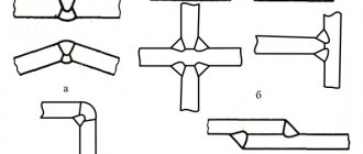
- Angular. It is used in cross-shaped, L- and T-shaped joints. Parts may be positioned at a deviation from a right angle, for example, a cross-shaped connection of the form “X” instead of “+”.
We recommend reading: How to calculate the strength of a weld
There are frontal and flank lap joints. The first is performed by welding the applied part along the end edge, the second - along the side edges on both sides.
Weld parameters.
In addition to the leg, the geometry of the weld is characterized by a number of parameters.
The main ones are:
- Width. Maximum horizontal size.
- Height. The same goes vertically.
- Convexity or concavity. Distance from the surface of the parts to the highest point of deposition.
- Penetration depth. The vertical distance from the surface of the parts to the bottom point of the molten metal.
The deep part of the seam is called the root. It is adjacent to unmolten metal. Boiling the root is the most critical stage when joining massive pieces. Seams in such structures are made in several approaches.
First, the root is formed, trying to weld the edges evenly and without defects with an electrode with a diameter of 3 mm. Then the thicker ones are reinforced with the required volume.
Weld length.
Calculation of the seam leg
Since a fillet weld is similar in cross-section to a triangle, you can find out the height and length of its sides using a geometric formula, using mathematical abilities. The calculation is made using the formula:
T=S*cos45º
The given components are deciphered as follows:
T is the size of the seam leg that we are trying to calculate
S - width of the roller (in geometry - the hypotenuse of the triangle)
cos45º is a standard value with a coefficient of 0.7
Let's calculate the leg of the weld in practice. For example, we have a corner connection with a bead width of 5 mm. We substitute this value into the formula and get 5*0.7=3.5 mm. This means the leg of the seam is 3.5 mm. This formula is applicable when the weld metal lies evenly on each side of the fillet joint.
The optimal parameters of the welding seam for each metal thickness were established experimentally. If you adhere to them, you will get a strong connection without wasting filler material. We present the characteristics of the weld in the table.
| Workpiece thickness, mm | Connection type | Minimum seam leg, mm |
| 4-5 | T-bar with double-sided penetration | 4 |
| 6-10 | T-bar with double-sided penetration | 4-5 |
| 11-16 | T-bar with double-sided penetration | 4-6 |
| 17-22 | T-bar with double-sided penetration | 5-7 |
| 23-32 | T-bar with double-sided penetration | 6-8 |
| 4-5 | T-shaped with one-sided penetration or corner with one-sided penetration | 5 |
| 6-10 | T-shaped with one-sided penetration or corner with one-sided penetration | 6 |
| 11-16 | T-shaped with one-sided penetration or corner with one-sided penetration | 7 |
| 17-22 | T-shaped with one-sided penetration or corner with one-sided penetration | 8 |
| 23-32 | T-shaped with one-sided penetration or corner with one-sided penetration | 9 |
As you can see, the size of the leg ranges from 30 to 100% of the thickness of the part - the thinner the workpiece, the closer the size of the leg is to its cross-section. When welding parts with different thicknesses, the leg is selected according to the larger indicator. For example, if you are welding workpieces with a cross-section of 5 and 10 mm with penetration on only one side, the leg of the weld should be 6 mm (taken from the calculation as if two sides were 10 mm thick). If you focus on the thin side, you will get weak reinforcement on thick metal and the connection will be unreliable. But in this case, it is important to choose the right amperage and cook with a certain arc technique.
Correct setting of the welding machine
The operating mode is determined by 3 parameters:
- tension;
- current strength;
- speed of electrode movement.
Setting up the device consists of selecting their optimal values.
The following factors influence this:
- Workpiece thickness.
- Material.
- Type of seam.
The parameters are selected experimentally, acting in the following sequence:
- Take an unnecessary fragment from the same material as the workpieces that need to be welded.
- Clean it with a grinder to a metallic shine.
- Set the voltage on the machine to 15-20 V and the welding current to 100 A.
- Light the arc and, by gradually adjusting the parameters, achieve stable combustion with good penetration depth.
- Record the optimal settings in writing or by taking photographs.
- Smoothly reduce the current until the arc goes out. Record the amperage at which this occurred.
- Return the regulator to 100 A, ignite the arc again and increase the current to the highest value. He is also recorded.
- Reduce the voltage by 0.5 V and determine the minimum and maximum current in the same way. Repeat this action several times, each time reducing the voltage.
- Return to optimal settings.
- In the same order, determine the upper and lower current limits, increasing the voltage several times in 0.5 V increments.
We recommend reading How quality control of welded joints is carried out
Points 6-10 of the instructions allow you to determine the extreme points of the range within which the device can be adjusted before working with other workpieces.
When setting up a semi-automatic machine, the feed rate of the filler rod is selected depending on the current strength: the greater the amperage, the faster the material should flow.
Consequences of incorrect leg calculations
We have already considered the negative consequences of a large leg. The second common mistake is that the seam leg is too small. Then there is little deposited metal on the sides, which reduces the strength of the connection. If it breaks or vibrates, the structure may not withstand the load and the seam will crack. Although the small leg saves consumables, it is only acceptable for non-essential connections (barbecue, table, etc.).
Another mistake welders make is an asymmetrical leg. Most often, the bottom flange of the seam is too wide, and the top flange is too short. This happens when the technique is incorrect or the welding mode is selected, because the molten metal flows down under the influence of gravity. The seam looks wide, but only slightly extends to the vertical side, so it holds weakly and is not designed for serious loads.
Features of strengthening welds
Reinforcing regular welds is not that difficult, but when it comes to fillet joints, they will require a special approach.
The task will be complicated by the fact that often when strengthening a seam by increasing its length it is necessary to use additional overlaps, ribs, overlays and other structures. And they are selected individually according to the size of the welding area, its location, the material that was welded, the characteristics of the leg, etc.
Diagram of a weld with and without reinforcement
What affects the weld leg
The formation of the weld leg of corner and T joints is influenced by a number of factors:
- Directionality of the torch or electrode.
If you weld fillet welds while holding the electrode or torch at an angle of 45º, then the liquid metal will flow down to the bottom shelf under the influence of gravity, lowering the vertical leg. Experienced welders in this case change the angle by 20-30º, directing the end of the electrode to a vertical surface. This is how you can change the height of the leg and achieve an equilateral triangle in the cross-section of the seam. - Position of the product in space.
It is easier to obtain a uniform seam on a corner joint by placing the product “in a boat”. Then the surface of the weld pool is smooth, the metal does not flow anywhere and covers both sides being joined equally.
- Arc speed.
When carried out quickly, the seam turns out to be narrow, and the leg is often small. Welding with a delay leads to an increase in the height of the seam and the growth of the leg. The welding speed must be selected on the rough workpiece, having tried different options, and only then move on to welding the critical product.
- Current strength.
Low current strength facilitates the application of filler metal from above, without deep penetration. The leg turns out to be large, but the quality of the connection is poor. Too high a welding current leads to deep penetration, but increases the fluidity of the metal and promotes undercuts on the vertical side, which is also a defect.
- Inductance.
Determines the transfer rate of a drop of molten metal during semi-automatic welding. The correct settings help to warm up the part well, apply a neat seam, and reduce spattering.
- Characteristics of filler metal.
If the core of a consumable electrode or the wire of a semi-automatic machine has high-temperature additives, then the weld pool becomes thicker, which leads to the growth of the leg. Low-temperature alloys flow faster, reducing the height of the weld leg.
Influence of welding speed and mode
There is a dependence of the weld cross-section configuration on the process parameters:
- As the current increases at a constant voltage, the temperature increases, so the penetration depth becomes greater. But with excessive amperage, metal can be burned.
- An increase in voltage at a constant current leads to an increase in the length. If there is an excess, lack of penetration is possible.
- As the speed of movement of the electrode increases, the heating temperature of the metal decreases. The seam width and penetration depth are reduced. At speeds above 50 m/h, the lack of temperature leads to the formation of defects that make the seam weak.
- The viscosity of the electrode material affects the shape of the amplification. The higher it is, the more convex the surfacing becomes.
We recommend reading: What are the types of defects in welds?
The welding mode is selected according to the workpiece with the smallest thickness, so as not to burn through it.
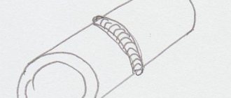
What is a bead in welding
A welding bead is a weld metal deposited as a result of a single movement of a heat source, i.e. as a result of one pass. The picture presented below will help you understand what is called a bead in welding (in vertical and overhead spatial positions).
To obtain a narrow roller, noticeable oscillatory movements of the electrode should be avoided. This type is most often used when welding the root of a seam, when working with thin-walled products, and when welding undercuts.
A widened bead (width does not exceed 14 mm) is obtained when welding is performed by transverse vibrations; used when welding thick-walled parts, as well as fillet and horizontal welds.
A wide bead (more than 14 mm) is used when welding filling layers. So, we helped the novice welder learn what a welding bead is. Now let's talk about the necessary theory of the welding process.
Regulations
The main document regulating the geometry of welding seams is GOST 5264-80, according to which the main geometric characteristics are calculated using mathematical formulas. The cross-sectional dimensions and lengths according to GOST 5264-80 depend on the type of connection, the thickness of the structural parts, and the geometry of the processing of the end edges. In addition, when calculating the geometric parameters of welding joints, other regulatory documents are taken into account: SNiP II-23-81, instructions and technical regulations. Among all the geometric characteristics of welds, the main ones are the minimum length, width, depth, leg size and some others.
Cutting pipes for welding
GOST 16037-80 regulates not only the types of welded joints of steel pipelines (butt, lap and corner), but also the characteristics of preparatory measures taking into account the type.
Before carrying out welding work, it is necessary to carry out preparatory measures. These include:
- Mechanical cleaning of products . It is required to remove dust, traces of corrosion and oxide film.
- Chemical treatment to remove oil, grease and film stains.
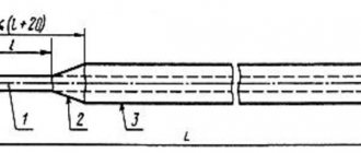
- Edge cutting.
Cutting involves mechanical processing of the edge. During pipeline installation, cutting is carried out using special machines. When carrying out repairs, cutting using angle grinders is allowed.
Edge cutting must be performed when the thickness of the workpieces for welding is from 4 mm. For corner joints, bevel one or both edges at a 45-degree angle.
Joints on steel pipelines can be rotary or fixed. When welding a pipeline, it is recommended to use the first type, since they allow the welder to take the most advantageous lower position. The edges are cut along the entire perimeter.
With a butt connection, the difference between the wall thicknesses cannot be more than 10% and exceed 3 mm.
Before installation, the edges and heat-affected zone are also processed to 20-30 mm. It is cleaned of mechanical impurities, corrosion traces and oil and fat stains.
Before electric arc welding, the ends of the pipes must be tacked to each other. For pipe diameters not exceeding 300 mm, 4 tacks are made. If it exceeds 300 mm, then tacks are made evenly every 200-300 mm.
Welding of pipes with a thickness of more than 12 mm is carried out in three steps (penetrations).
If thick pipe blanks are connected, then the formed seam must be made thicker than the part itself. To form a connection with the specified parameters, you need to cut the edges after chamfering. At the same time, the electrode is provided with access for high-quality welding of the seam.
When calculating technological cutting parameters, special attention should be paid to the correctness of the calculation and compliance with certain cutting values. This reduces labor intensity, allows you to use materials economically and control costs.
When preparing joints, the type of chamfer depends on the thickness of the workpieces: with a thickness of 3-25 mm, a one-sided chamfer is used, with a thickness of 26-60 mm, a double-sided chamfer. For corner joints, the following boundaries are set: for values up to 20 mm - one-sided, up to 50 mm - two-sided.
Based on the geometric shape of the profile, the following subtypes of cutting are distinguished:
- Traditional (standard) bevel with a trapezoidal profile.
- X-shaped, when two bevels are made in such a way that the profile resembles the outline of the letter X (practice for using a workpiece with a thickness of 3-25mm).
- U-shaped, where the cross-sectional profile has a curved shape and resembles the letter U. GOST recommends using this form for large workpiece thicknesses (26-60mm) to reduce the cross-sectional area and reduce material costs.
If the pipe has a thickness of over 60 mm, then special shapes are used (in particular, ledges and complex curved profiles).
Gas cutters and mechanical processing are used for cutting. The first method has certain limitations and disadvantages: it has low qualities. The highest accuracy is ensured by milling; for large-diameter pipes, special trimming machines or grinders can be used.
Thus, GOSTs for welding activities are an important document that regulates the conditions for preparing and carrying out welding work. GOST 16037-80 defines methods for welding steel pipelines, types of connections, cutting methods and structural elements for each type. Compliance with the recommended parameters extends the service life of pipelines, ensures durability, strength and tightness of seams.
Reinforcement of butt seams
Strengthening butt welding is complicated by the fact that most often its strengthening can lead to damage to the joint. For example, if the butt seam is made along the entire length or height of the metal components, then no reinforcement can be done at all. Surfacing will create excessive concentration at the melting point, due to which the surfacing can not only deteriorate, but also completely collapse. The thing is that the height of such welds is determined only by the elements being joined and taking into account the structure of the bead of the connection itself. This roller is the protrusion.
If the butt welding still needs to be processed, then you first need to relieve the tension with abrasive tools. After this, the area of the overlays is calculated, with the help of which the seam will be strengthened.