Edge cutting is performed when welding metal structures with a thickness of 5 mm or more. This should be perceived not as a wish, but as a necessary condition because such a procedure is provided for by GOST. Only this approach to welding can ensure a high-quality seam and reliability of the welded structure.
1 / 1
Edge cutting is performed when welding metal structures with a thickness of 5 mm or more. This should be perceived not as a wish, but as a necessary condition because such a procedure is provided for by GOST. Only this approach to welding can ensure a high-quality seam and reliability of the welded structure. Qualified welders are required to possess this knowledge and apply it in practice. GOST standards exist for each type of welding. GOST 5264-80 for manual arc welding describes edge shapes for all types of joints:
- for butt - 15 types;
- for corner - 5 types;
- for T-bar - 4 types;
- for overlap - without bevel.
Cutting edges for welding
To obtain high-quality welds, it is necessary to cut the edges of the parts. Grooving is a change in the geometry of the edge of a part. Simply put, the end of the part is cut off at a certain angle on one or both sides.
The angle and shape of the groove are determined by a regulatory document, most often this is GOST for the type of welding that will subsequently be used to connect the parts. Most often this is GOST 5264 (for sheet and profile products) and GOST 16037 for pipes.
Features of cutting methods
When oxyfuel cutting of alloy steels, free carbon forms carbides, which are very difficult to remove. Therefore, the preparation of alloys such as chrome-plated stainless steel, for example, is carried out in other ways. Gas beveling is used mainly for carbon steels.
The quality of manual thermal cutting almost always leaves much to be desired, so it is necessary to additionally treat the cut with abrasive. In addition, the composition and properties of the top layer change, which leads to deformation of the products.
Plasma cutting allows you to get a high-quality cut of almost any metal. Air is used as the plasma-forming gas. Portable thermal cutting devices are equipped with gas and plasma torches. When installing three burners, you can make K-shaped bevels on the edges.
With machine thermal cutting, the quality of the edges is high and meets the requirements of GOST standards. Laser cutting of edges is used when there is nothing to replace it with, it is very expensive.
Mechanical cutting ensures high-quality edge bevels. The advantages include the creation of bevels of complex shapes. But there are also significant disadvantages, including low productivity and difficulty in forming edges on large workpieces.
When forming double-sided bevels using a mechanical method, turning of the workpieces is required. Cutting joints with abrasives is hazardous and requires a lot of manual labor. Abrasive elements cause cracks.
Why is edge cutting done when welding?
Edge cutting is carried out in cases where it is necessary to weld parts with a thickness of more than 3-4 mm. Thinner parts can be welded without cutting, since the arc will melt metal of such thickness. The cutting of the edges ensures uniform filling of the cross-section of the parts with filler (electrode) metal.
In simple terms, edge cutting is necessary to weld the parts and not leave unfused areas. It provides a smooth transition between the weld and the base metal. The latter, in turn, reduces the stresses that appear in the metal during welding as a result of heating.
Mandatory training
The only purpose of cutting edges is the desire to obtain a high-quality, reliable seam. The cutting is carried out so that the electrode can easily reach the lower layers and boil the product throughout its entire thickness.
Preparation of edges before welding is carried out in any case. She may be:
- without cutting;
- with flange;
- with cutting.
The mandatory preparatory stage consists of cleaning the end and adjacent area from all kinds of mechanical and greasy contaminants, oxide films, and rust to a distance of at least 20 mm in accordance with GOST.
Cleaning joints for welding can be done manually using sandpaper, a brush with metal bristles, a file, a grinder, or using chemical reagents.
Once the parts are assembled into an assembly that is to be welded and fixed, it will no longer be possible to properly process the edges.
It is recommended to prepare joints when the wall thickness of the parts being welded is 5 mm or more . One-sided flanging is performed when welding butt and corner joints.
Double-sided flanging is performed during butt welding. In general, cutting involves giving the edges a certain shape, as a result of which they become thinner.
Edge bevel angle
As already mentioned, the bevel angle is determined by the regulatory document. The most commonly used angle is 45 degrees at connections such as C8, C9, C10, C11 and C12, C15 and C43. Also an angle of 25 degrees at connections C17, C18, C20, C21, C25, C39, C45. The designations are taken from GOST 5264. These are the 2 most common edge cutting angles for sheet structures and profile structures.
If we talk about the pipe, then the most common cutting angles are 30 degrees used in such connections as: C17, C18, C19, C46, C49, C50, C51, C54, C55, C56 and a less common angle of 50±3 degrees which is used in compounds C8, C10, U15, U17, U8, U19, U20, U21.
Preparation of edges of process pipelines (NGDO4,12, OKHNVP16, MO2, GDO)
Deviation from perpendicularity of the end of the pipe relative to the generatrix: 05 mm. for DN up to 65mm; 1.0mm. for DN over 65mm. up to 125mm; 1.5mm for DN over 125mm. up to 500mm; 2.0 mm for DN over 500 mm (clause 7.1.18. PB 03-585-03)
The edges of pipes (elements) and adjacent areas on the internal and external surfaces are at least 20 mm wide. must be cleaned from rust and dirt to a metallic shine and degreased (clause 7.1.19. PB 03-585-03)
Gas, air-arc or plasma cutting of pipes made of hardening heat-resistant steels must be carried out with preheating at 200-250 C and slow cooling. After cutting, the edges must be checked by penetrant or powder flaw detection. Detected cracks are removed by mechanical cleaning along the entire edge. (clause 7.1.16., 7.1.17 PB 03-585-03)
After thermal cutting, the edges of pipes made of hardening steels must be cleaned to a depth of at least 3 mm, and those of carbon and austenitic steels to a depth of at least 0.5 mm. from the largest depression of the cut (clauses 18.20,18.21 RD 38.13.004)
Preparation of pipeline edges for boiler equipment (KO1,2)
The ends of pipes made of carbon and low-alloy steels can be processed by oxygen, plasma-arc or air-arc cutting, followed by cleaning the edges with a cutting or abrasive tool until traces of fire cutting are removed. The edges prepared for assembly must be free of breaks, burrs, sharp transitions and sharp corners.
The edges and adjacent areas of the surfaces of the parts must be cleaned to a metallic shine and degreased to a width of at least 20 mm along the outer surface. from the cutting edge, at least 10 mm on the inside. When installing the fitting, the surface on the seam side must be cleaned to a width of 15-20 mm. from the hole, and the surface of the glasses to the entire depth. (clause 6.2.4. RD 153-34.1-003)
Oxygen cutting of pipes made of chrome-molybdenum and chrome-vanadium steels with a wall thickness of more than 12 mm. at air temperatures below 0 C, it is necessary to carry out preheating at 200 C and slow cooling. (clause 6.1.5. RD 153-34.1-003)
When thermally cutting high-alloy steels (martensitic, martensitic-ferritic and austenitic classes), an allowance of at least 1 mm must be provided. for subsequent mechanical processing (clause 6.1.4. RD 153-34.1-003)
Preparation of edges of building structures
Immediately before welding, the edges and adjacent areas are 20 mm wide. for manual or mechanized arc welding and at least 50 mm. for automatic, as well as the junction of the initial and output strips must be thoroughly cleaned of scale, dirt, paint, oil, rust, moisture, snow and ice. (clause 5.6. RD 3415.132, clause 1.4.2 OST 36-58, clause 6.5 OST 36-60)
Fire cutting of edges of parts made of steel C345 and more durable at ambient temperatures below minus 15 C should be carried out with preheating of the metal in the cutting zone to 100 C. (clause 5.5. RD 3415.132)
After thermal (oxygen, air-arc, plasma) cutting, the cut surfaces must be mechanically processed:
- on elements made of steels C235 to C285 - until cutting marks are removed
- on elements made of steels C345 to C375 - with removal of a layer with a thickness of at least 1 mm.
- on elements made of steels C390 to C440 - with removal of a layer with a thickness of at least 2 mm.
When processing with an abrasive tool, the stripping marks should be directed along the edges (clause 5.3. RD 34 15.132).
Types of edge preparation
Let's consider all types of edge cutting that are found in regulatory documents for welding.
V-shaped
The V-shaped edge groove is the most common and easiest to perform. The ends of the parts are ground down and when viewed in cross-section, the edges seem to create the outline of a Latin letter - V.
When performing such cutting, the edges are also blunted, which prevents burning and leakage of the weld pool metal.
X - shaped
Now let's consider this type of cutting as an x-shaped cutting. It, like the V-shaped cutting, is used quite often. It is actually a V-shaped cut of the upper and lower parts of the part, forming, as it were, the letter X.
It is used in cases where thicknesses exceed 8 mm, this is when welding sheet and profile structures. If we are talking about welding pipelines, then the X-shaped groove is used already with a thickness of 3 millimeters or more (for example, connection C56 according to GOST 16037). Its use provides a less wide seam than if a V-shaped groove was used. This will correspondingly reduce the stress in the weld metal.
U-shaped
U-shaped cutting of edges is used in cases where high welding quality is required at the same time (minimal welding deformation design) and at the same time the parts being welded have a sufficiently large thickness of 15 mm or more in accordance with GOST 5264. This cutting is most often performed in the factory , it is quite difficult to perform during installation.
K - shaped
The K-shaped edge groove is very similar to the X-shaped one, except that the groove is made on only one wall of the part. It is used for welding products with wall thicknesses from 12 mm up to 100 mm.
Let's make a short summary: V and U-shaped cuttings are done on one side, K and X-shaped ones are cooked on 2 sides. This must be taken into account before starting work and at the design stage, because if there is no access to the reverse side, then there is no point in planning such cutting.
Offset parts
The edges do not have to be symmetrical or parallel to each other. However, the displacement of the edges of butt welded joints is limited. All tolerances are specified in regulatory documents. The amount of permissible displacement depends on the thickness of the parts being connected.
Welding pipelines and other various pipes has its own nuances. This will require increased precision. The permissible displacement of the edges when welding pipes will be much less than for parts that have a flat shape. A way to prevent the occurrence of significant displacement is to securely fix the elements being connected. A proven method of fixation is to use tack welds—short transverse seams.
Designations on the drawings
The main types of edge preparation for welding are not indicated in the drawings. When designating a weld seam, the drawing indicates the regulatory document in accordance with which the seam is made, as well as the type of connection itself, its symbol. You can read more about how welding seams are designated in a drawing in our article - How welding seams are designated in drawings - welding symbol.
Specialized equipment
Not only universal equipment, but also highly specialized equipment is suitable for cutting pipe edges for welding. You can choose based solely on the volume of work.
If we talk about universal machines, we can highlight angle grinders, bench tools and files.
Promotech presents a huge selection of narrowly targeted chamfering machines: edge cutters and chamferers of the BM and PRO series, which are perfect for performing a large volume of similar seams.
Preparation of edges for welding
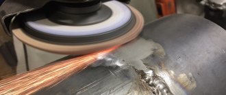
Cutting is carried out mechanically or thermally. If cutting is carried out mechanically, then most often a grinding machine (angle grinder), special machines - chamfers, using a milling or lathe, and occasionally files are used. If the cutting of edges is carried out thermally, that is, the metal is removed using gas or plasma cutting, air-arc gouging, and then the edges are still processed mechanically. We'll talk more about the equipment later.
Do you know all types of metal welding? Follow the link and check yourself.
Cutting methods
Cutting an edge involves removing part of the metal from the end of the part at an angle. The angle is determined between the plane of the end and the resulting bevel.
Cutting can be done mechanically and thermally. Subsequently, depending on the quality of the formed surface, mechanized or manual finishing is carried out.
Mechanized finishing is carried out on boring equipment for rotating bodies. For straight surfaces, milling machines or pneumatic grinders are used.
If there is no special equipment, then the surface for welding can be modified manually using a chisel and file.
Thermal methods for cutting edges are gas (using oxygen), plasma and laser cutting. When thermal cutting, you can get K-, V-, and X-shaped edge bevels. Mechanical methods include milling, planing, abrasive cutting and slotting devices.
Mechanical cutting equipment
To create a bevel of edges for welding, various equipment is used, ranging from the simplest files to complex automatic systems with program control.
If you want to know what the NAKS registry is and how you can work with it to check your IDs, if so, follow the link.
Machine tools
If we are talking about the factory production of parts and blocks, then cutting the edges is most often performed on lathes and milling machines, depending on the configuration of the parts. In installation or small-scale production conditions, manual machines called chamferers are used. Currently, there are a very large number of them, ranging from simple manual ones like “Mongoose” to automated complexes of German and Czech production, for example BDS (made in Germany) NKO Machines (Czech Republic).
Edge cutting machines are divided into edge milling, edge planing, and edge splitting. Edge planers are used only for straight workpieces, but they can be used to produce even curved edges.
Edge milling machines - machines belonging to this group cope with curved surfaces; the working tool is a milling cutter. Often these machines are equipped with CNC. Edge splitting machines are the most highly productive, but the processing is rough and is used for large parts. Afterwards, additional edge processing is required.
Equipment and hand tools
Most of the time during installation construction work, cutting of edges is carried out using grinding machines with abrasive wheels with diameters of 125 and 250 mm. If the thickness of the parts is small, then you can use a file.
Bevels
Joints with grooved edges are available with one-sided bevel of one or two edges and with double-sided bevel of one or two joints. Bevels can be straight or curved, with or without blunting.
When welding on one side, the joints are cut in the form of the letter V or U. When welding on both sides, K or X-shaped grooves are made. Cutting for one-sided welding is more labor-intensive than for welding on both sides.
The choice of edge bevels for welding is determined by the design of the products being welded, the thickness of the metal and the diameter of the electrode. The shape of the cut is determined by the angle and shape of the bevel, as well as the height of the bluntness.
The blunt part is the part of the joint that is not beveled. It is necessary for the correct formation of the weld and to prevent burn-through. The dullness varies in thickness from 1 to 3 mm.
Sometimes they do without it completely. Then special measures are taken to prevent burn-through of the weld. Welding is carried out on a lining, a flux base, or using a locking connection.
When using manual electric arc welding, edge preparation for metal less than 5 mm thick is not done. If the product is thicker, then a one-sided symmetrical cut with an angle of 60°-80° and a bluntness of 1-3 mm is usually used.
For butt joints with K-, V-, and X-shaped edge processing, the cumulative bevel angle is 45°-55°, and when welding with a backing - 10°-12°. These parameters affect the properties of the seam and directly determine its characteristics.
Edges for parts of different thicknesses
There is often a situation where you need to weld parts that differ greatly in thickness. In this case, GOST has special tables, guided by the data from which you can understand how to assemble the connection. If the values from the table do not exceed the permissible values, then the edges are cut as for a thicker part with a smooth transition from a thin part to a thicker one.
It looks something like the picture below.
If the condition is not met, then it is necessary to make a smooth bevel for the thicker part to the thickness of the second (thin) part.
Table for parts of different thicknesses
| For pipelines according to GOST 16037 | |
| Thin wall thickness | Thickness difference |
| Until 3 | 1 |
| More than 3 to 7 | 2 |
| More than 7 to 10 | 3 |
| More than 10 | 4 |
| For metal structures according to GOST 5264 | |
| Thin wall thickness | Thickness difference |
| Up to 4 | 1 |
| More than 4 to 20 | 2 |
| More than 20 to 30 | 3 |
| Over 30 | 4 |
For elements of different thicknesses
butt joint with flange (for thin metal)
Different structures and elements have different wall thicknesses:
- when working with thin-walled products (up to 5 mm), cutting edges is not required;
- the presence of edge flanging also does not require cutting them;
- if the wall thickness of the parts is from 5 to 20 mm. It is recommended to carry out a one-sided bevel;
- with product thicknesses from 20 to 60 mm. two-sided cutting should be done.
These rules are standard for different parts and for different types of connections.
#10
Sent 14 February 2022 - 12:35
For what? After all, on the flange of the angle there is already a ready-made edge for welding (radius) and on the channel it’s the same... I roughly imagined how you want to weld it.. But it would be better if they showed the assembly. If the edge for welding is standard, then choose from the GOST 5264 table. And if it is not standard, then the designer must show all dimensions (gap, bluntness, chamfer..)
ingenerkons and Chertil like this
Sincerely
Olzhas
One is groping through the dark labyrinth - maybe he will stumble upon something useful, or maybe he will break his forehead. Another will take at least a small flashlight and shine it in the dark. And as he walks, his lantern glows brighter and brighter, finally turning into an electric sun, which illuminates everything around him and explains everything. So I ask you, where is your lantern! (D.I. Mendeleev.)
#11
Sent 14 February 2022 - 20:45
What’s strange is that there is a procurement shop, where they cut it to size with an allowance and take it to sections.
In addition, technologists often skip such details without a drawing, and it turns out that the work is done, but there is no paperwork to pay for.
#12
Sent 17 February 2022 - 00:04
and why did such a question arise? The technologist cannot decide on standard seams according to GOST??? and why are you worried about the technologist, who is supposedly supposed to be helped by the designer, is this what you decided among yourselves???
Whether he should lay the edges for welding or not is a question for the designer, his boss and the chief. engineer, not yours, he doesn’t discuss whether you owe him anything together with the technologist
And what GOST regulates for welding should be known by the technologist and your master...
if you said a non-standard seam, what to do, and without looking at GOST, immediately saying that someone must do something is somewhat fleeting
(I would answer if you can’t weld the butt joint properly, I’ll lay down the edges with weld root welding, and also on the lining, and I’ll also give an x-ray 100%, so that’s my right, we decided so, so I’ll show off my mind)) just for fun )
#13
Sent 17 February 2022 - 20:16
And such questions arise when one boss wants to push more work onto a neighboring department, we now almost have this as a rule at the enterprise, we need edges, which means there will be a drawing.
Edge processing methods
Now let's talk about how edges are processed for welding. Processing is a very important stage, because if there is dirt on the edges, various inclusions, as well as lubricants or paint, they will certainly lead to the formation of unacceptable defects.
To avoid this, after they have already been prepared, the edges are re-cleaned, wiped, and also degreased using solvents, degreasers or a water-alcohol solution. In some cases, acids and alkalis are used to degrease edge cleaning.
Preparing blanks for cutting
The procedure consists of the following steps:
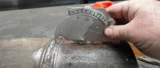
- Calculation of configuration and chamfer angle. The cutting angle of the edges is determined by the type of connection, the purpose of the part and the thickness of the metal.
- Cleaning the end surfaces. This operation is performed to remove rust, oxide layer, scale and other solid contaminants. Poor cleaning of workpieces leads to the appearance of pores, lack of penetration, slag inclusions and sagging. The oxide layer can be removed either mechanically or chemically. In most cases, steel brushes, grinders, sandpaper or a file are used for processing. During mechanical stripping, up to 2 mm of metal is removed.
- Removing contaminants. The next stage of preparation is to thoroughly clean the ends from oil and other substances that can lead to irreversible seam defects. Organic solvents are used to degrease surfaces. To clean the edges from the oxide film, use strong acids.
- Cutting operations. The last stage provides access to the entire joint surface and corrects the shape of the edges.
The following types of technological operations are used in production:
- straightening with a hammer by hand: used for preparing metal plates;
- mechanical finishing: performed with correct rollers that eliminate warping, unevenness and other surface defects;
- part marking: carried out if welding is necessary during repair work or the seam has a complex curved shape;
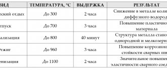
- heat treatment: used to relieve thermal stress, diffusion equalize the composition and increase the ductility of the metal.
To avoid the formation of cracks and high residual stresses, the method of preheating parts is used.
Edge cutting technology
The edge cutting technique itself, as a rule, does not cause difficulties in understanding when the process is performed using angle grinders (grinding machines) or a file. The parts are taken and the end is ground down and the required edge angle is created. As a rule, this is followed by dulling of the edges.
If the edges are prepared on a milling machine, the product is fixed at the required angle relative to the cutter, which grinds down the metal in the process, then we require an angle. The result is edges with precisely maintained geometric dimensions.
In cases where the edges are prepared on a lathe (this applies to rotating bodies such as round timber, pipes, etc.), the products are installed in the chuck of the lathe, and the excess metal is ground off with a cutter to the required dimensions, creating the desired angle and bluntness. This method also ensures dimensional accuracy.
Sometimes thermal cutting methods are used to cut edges, such as plasma, gas, air-arc and laser cutting. With the exception of laser, after all of the methods given here, the edges must be machined, as the surface will be uneven. It will have deep channels, as well as sagging and splashes of metal. We will not dwell in detail on the preparation and implementation of the cutting process within the framework of this article.
The technology itself consists in cutting off a layer of metal from the end of the product at a close to a given angle. Thermal methods are usually used when thicknesses are greater than 10 mm.
At smaller thicknesses there is not much point in using them, since eliminating defects obtained during the cutting process takes quite a lot of time. And at these thicknesses, this is comparable to the same time that would be spent if the process were performed manually using a grinding machine.
Using manual edge cutters simplifies and speeds up the process of obtaining the desired angle. This device is installed on the end of the product, it is connected and the metal is removed. The quality of the edges is higher than when using an angle grinder, but lower than when using a milling or lathe.
Such devices speed up the process, especially when the diameters are small and there are a lot of joints. In these cases, it is actually an irreplaceable thing.
Butt joint
A butt connection is a type of connection in which parts are connected to each other at their ends. As mentioned earlier, if the thickness of the part is up to 2.5-3 millimeters, then edge cutting is not performed (unless, of course, there are special requirements for the welded joint).
Gusset
Corner joints (seams) have an angle between the part and the edge of the surface being welded. For them, just as for butt joints, the condition of up to 2.5-3 mm is met; you can not cut the edges, because such a small thickness can be welded just like that. Corner connections (pipes insertions) with a diameter of more than 100 mm must be made with mandatory cutting of the edges. This requirement applies to steam and hot water pipes, as well as petrochemical pipes.
Useful article - How to weld using electrodes correctly
Cutting pipes for welding
In this section we will talk in more depth about cutting the edges of the pipe. Welding of pipelines accounts for more than 60% of all welding work, therefore pipe cutting is an extremely pressing issue.
When preparing pipe joints, the following connections are used:
- Angular
- Overlapping
- Butt
Angle – used when welding pipe to pipe, pipe with insert (fitting and boss), as well as pipe to flange.
Lap joint - used to connect a pipe to a sheet (plug) or welding flat flanges. As such, edge cutting is not performed in this case. The end of the part to be welded and the welding area are simply prepared and cleaned.
Butt welding – used for welding pipe to pipe, to an elbow, to a tee, collar flanges, to shut-off valves, and so on. This is the main type of connection when welding pipelines.
When welding pipelines, the most common is the C17 butt joint with one-sided groove without the use of backing rings. Almost 80% of pipelines are welded with this type of connection. The second most popular are connections C18 and C19 with a remaining or removable backing ring. The bevel angle of the edges for all these types of joints is 30 degrees, with a tolerance of ± 3.
Pipelines with a wall thickness of 2 to 3 (sometimes up to 5 mm) are welded without cutting edges according to connection C2. With this connection, the ends of the parts are simply cleaned to a metallic shine and degreased, and then the joint is assembled, tacked, and welding is performed.
As a rule, of course, starting from a part thickness of 3 millimeters, the edges are cut to ensure penetration and prevent defects at the root of the seam.
Before starting to cut the edges, a very important condition is the perpendicularity of the ends of the pipe.
The deviation from perpendicularity should not be more than one millimeter, otherwise there will be a very large gap in the joint, which, even if it can be welded, will still be a defect since there will be multiple defects in the seam.
Another very important condition is the straightness of the already assembled joint. There should be no fracture at the junction exceeding 1.5 millimeters. This is checked by applying a 400 mm long ruler in 3 different planes.
For bends and tees
It is difficult to imagine a long pipeline without a branch. An elbow is a curved piece of pipe. Bends are made from flexible pipes (sometimes bends are made from pieces of metal - sectors that are welded together). In most cases, bends are welded to the pipe using a butt joint. The cutting of edges is usually performed at an angle of 30±3 degrees (the angle between the axis perpendicular to the axis of the pipe) since the C17 connection method is most often used.
Useful article - What kind of silumin alloy is this?
For fittings and bosses
Fittings and bosses are used to extract part of the medium from a pipeline or to insert various sensors. The fittings are made from pipes, and their length is usually not large, from several tens to several hundred millimeters.
Fittings and bosses are characterized by one-sided cutting of edges of 50±5 degrees, or without cutting of edges at all in cases where this is allowed by the design. If the thickness of the fitting is more than 3 mm and the edges are not prepared, then such a connection will have a structural lack of fusion. The cutting used is U17, U18, and in the case when the edge is cut then U19, U20, U21.
For vessels and tanks
For welding vessels and tanks operating under pressure, there are regulatory documents that tell you how to perform welding work and what is normal and what is defective. But if we are talking about cutting edges, then GOST 5264 still helps us.
Do you know what TIG welding is? If you want to find out, follow the link to our article.
Most often, a one-sided V-shaped cut is used where the thickness is not large (up to 12-15 mm) and there is no possibility of welding on the reverse side. If the thickness is more than 15 millimeters, then it is U-shaped. If it is possible to reach from both sides and the thickness is more than 8 millimeters on both sides, then an X-shaped one is used.
For I-beam
During manufacturing, I-beams or I-beams are welded using a T-joint, and during installation they are connected to each other using butt welds. Here everything is still decided by GOST, according to which the choice of cutting is made.
To weld the upper and lower flanges and the I-beam stand, a cutting with a bevel angle of 45 degrees is used with a permissible deviation of ±2 degrees (connections T8 and T9). Beams can also be welded without cutting the edges, but only when structural lack of penetration is allowed. This is determined by designers at the design stage and supported by calculations.
Cutting cracks in metal
If a crack(s) appears in the metal and needs to be repaired, this is done in several stages. The first thing you need to do is make a sample - select the crack itself and the metal around it. The shape of the sample should resemble the shape of a bowl, with smooth transitions to “healthy” metal and an inclination of the walls from 25 to 60 degrees.
If the crack is through, then it needs to be drilled with a drill with a diameter of 3–5 mm. A plate 2–3 mm thick is installed on the crack, which exceeds the length of the crack by 5–8 millimeters. After which it is tacked at several points (usually 5–6).
Methods for cutting seams of overlap welded joints
In the case when an overlap connection is made, one part is placed on the other, welding occurs along the edges of both parts. In this case, cutting of the edges is not provided technologically, only preparation for a tight fit of one plane to the second. The parts are connected by two welds, which connect the edges with closer flat surfaces.
a connection without reinforcement when connecting overlapping parts with a thickness of no more than 10 mm. In this case, a double seam is made for sealing reasons, that is, to prevent moisture from getting between the overlaps and an increased corrosion process does not occur. The joining method itself is called “lap joint with front seams”.
A connection with reinforcement is performed under special requirements for strength, as well as when the metal of the welded products is large. The figure shows an overlap welded joint with additional welded fasteners, which are obtained by heating the lower and melting the upper part, as well as those that are sawed in advance at the weld joint. In addition to auxiliary fastenings, in rare cases they can also be made without frontal seams when the thickness of the products is small, but in this case you should not count on special strength.
Edge surface quality control
The inspection of the surface of the edges is primarily carried out by the welder himself, visually inspecting for defects, and also measuring the bevel angle and bluntness. Next, the edges are checked by a level II–III welding specialist (this is a welding master or engineer). This is a standard control scheme at enterprises. If non-destructive testing is required, the inspection is also carried out by a flaw detector.
When carrying out control, the following is checked:
- Distance of stripped metal from cutting.
- Edge bevel angle and bluntness dimensions.
- Are there any unacceptable defects on the surface (metal peeling, cracks and rough nicks).
- If the part being welded is critical, in some cases non-destructive testing of edges is used (ultrasonic, magnetic or PVC)
Common Mistakes
Very often, correction of defects and modification of welding joints is caused by inaccurate preparation of the seam. To get good welding results, avoid these common mistakes:
- Very often you can find beveled edges with an angle that is too sharp, which leads to poor penetration of the weld seam into the depth of the weld joint.
- Not good enough to remove oil, dirt, paint or varnish from the base metal. Improper cleaning methods can cause the grout to become porous. Using grinders is the fastest way to clean the welding area. Make sure you clear at least 2-5cm from the end of the piece to prevent foreign material from getting into the seam.
- Not following welding procedures may seem like a good way to save time and increase productivity, but it can also lead to further rework, corrections, and failed welds. Before welding pipes, you should familiarize yourself with the specifications and technological processes, they usually contain the correct bevel angle, gap size, weld root size and other important details.
Structural Elements of Welded Joints
The shape of the edges and their assembly for welding are characterized by three main structural elements: the gap, the blunting of the edges and the bevel angle of the edge (Fig. 11). Type and angle of cutting edges; determine the amount of electrode metal required to fill the groove, and hence the welding performance. X-shaped cutting of edges, compared to V-shaped, makes it possible to reduce the volume of deposited metal by 1.6-1.7 times. In addition, such cutting provides less deformation after welding. With X-shaped and V-shaped cutting, the edges are blunted to properly form the seam and prevent the formation of burns. Rice. 11. Structural elements of cutting edges for welding: a – angle of cutting edges; c - gap; s – dullness; p – edge bevel angle; 1 – without cutting edges; 2nd by cutting the edges of one part; ? – V-shaped cutting; 4
– X-shaped cutting;
5
– U-shaped cutting
The gap during assembly for welding is determined by the thickness of the metals being welded, the grade of material, the welding method, the form of edge preparation, etc. For example, the minimum gap value is prescribed when welding without filler metal of small thicknesses (up to 2 mm) or when arc welding with a non-consumable electrode of aluminum alloys. When welding with a consumable electrode, the gap is usually 0-5 mm; increasing the gap contributes to deeper resistance of the metal. The seam of the welded joint is characterized by the main structural elements in accordance with existing standards (Fig. 12).
Rice. 12. Basic geometric parameters of welds: e – width; q – convexity; h – penetration depth; b – gap; k – leg; S – part thickness
Control questions: 1. What structural elements characterize the shape of the edges? 2. What edge cutting forms do you know? What do V-, X- and U-shaped types of edge cutting mean? What role does the gap play during assembly for welding? What is edge blunting and why is it done? Explain the structural elements of a weld.
Chapter 3 GENERAL INFORMATION ABOUT STEEL AND THEIR WELDABILITY
Carbon Steels
Steels are divided into carbon and alloy. According to their intended purpose, a distinction is made between structural steels with a carbon content of hundredths of a percent and instrumental steels with a carbon content of tenths of a percent. The largest volume of welding work involves the use of low-carbon and low-alloy structural steels. The main element in carbonaceous
structural steels is carbon, which determines the mechanical properties of steels in this group. Carbon steels are smelted of ordinary quality and high quality. Carbon steels of ordinary quality are divided into three groups: group A – according to mechanical properties; group B – by chemical composition; group B – according to mechanical properties and chemical composition. The following grades of steel are produced: group A – St 0, St 1, St 2, St 3, St 4, St 5, St 6; group B – BSt 0, BSt 1, BSt 2, BSt 3, BSt 4, BSt 5, BSt 6; group B - VSt 0, VSt 1, VSt 2, VSt 3, VSt 4, VSt 5. According to the degree of deoxidation, ordinary quality steel has the following designation: kp - boiling, ps - semi-quiet, sp - calm. Boiling steel containing silicon (Si) no more than 0.07% is obtained by incomplete deoxidation of the metal with manganese. Steel is characterized by a pronounced uneven distribution of harmful impurities (sulfur and phosphorus) throughout the thickness of the rolled product. Local increased concentration of sulfur can lead to the formation of crystallization cracks in the weld and heat-affected zone. Boiling steel is prone to aging in the heat-affected zone and transition to a brittle state at subzero temperatures. Calm steel is obtained by deoxidation with manganese, aluminum and silicon and contains silicon (Si) of at least 0.12%; sulfur and phosphorus are distributed more evenly in it than in boiling steel. This steel is less prone to aging and has less reaction to welding heat. Semi-quiet steel, in terms of its tendency to aging, occupies an intermediate place between boiling and calm steel. Semi-quiet steels with grade numbers 1–5 are smelted with normal and increased manganese content, up to approximately 1%. In the latter case, the letter G is placed after the brand number (for example, BStZGps). Group A steels are not used for the manufacture of welded structures. Group B steels are divided into two categories. For steels of the first category, the content of carbon, silicon, manganese is regulated and the maximum content of sulfur, phosphorus, nitrogen and arsenic is limited; For steels of the second category, the maximum content of chromium, nickel and copper is also limited. Group B steels are divided into six categories. The full designation of steel includes grade, degree of deoxidation and category number. For example, VStZGps5 means the following: steel group B, grade StZG, semi-quiet, category 5. The composition of steels of group B is the same as that of steels of the corresponding grades of group B, 2nd category. Steels VSt1, VSt2, VStZ of all categories and degrees of deoxidation are produced with guaranteed weldability. Steels BSt1, BSt2, BStZ are supplied with a guarantee of weldability at the customer’s request. High-quality carbon steel is produced in accordance with existing standards. Steel has a low sulfur content. Permissible deviation for carbon (0.03-0.04%). Steels with a carbon content of up to 0.20% inclusive can be boiling (kp), semi-quiet (ps) and calm (sp). The rest became only calm. For subsequent mild steels, the letters “sp” are not placed after the numbers. High-quality carbon steels for the manufacture of structures are used in the hot-rolled state and in a smaller volume after normalization and hardening and tempering. Carbon steels, in accordance with existing standards, are divided into three subclasses: low-carbon steels with a carbon content of up to 0.25%; medium-carbon with a carbon content (0.25-0.60%) and high-carbon with a carbon content of more than 0.60%. Low-carbon steels are mainly used in welded structures. In welding production, the concept of weldability of various metals is very important. Weldability is the ability of a metal or a combination of metals to form, with the established welding technology, connections that meet the requirements determined by the design and operation of the product. According to weldability, carbon steels are conventionally divided into four groups: I – well weldable, with a carbon content of up to 0.25%; II - satisfactorily weldable, with a carbon content of 0.25 to 0.35%, i.e., to obtain high-quality welded joints of parts made from these steels, strict adherence to welding conditions, special filler materials, certain temperature conditions, and in some cases - heating, heat treatment; III – limited weldability, with a carbon content from 0.35 to 0.45%, to obtain high-quality welded joints which additionally require heating, preliminary or subsequent heat treatment; IV - poorly weldable, with a carbon content of more than 0.45%, i.e. welds are prone to cracking, the properties of welded joints are reduced, steels of this group are usually not used for the manufacture of welded structures. All low-carbon steels can be welded well using existing fusion welding processes. Ensuring the uniform strength of the welded joint does not cause difficulties. The seams have satisfactory resistance to the formation of crystallization cracks. This is due to the low carbon content. However, in steels containing carbon at the upper limit, the probability of cold cracks increases, especially with increasing cooling rate (increasing metal thickness, welding at subzero temperatures, welding with small-section seams, etc.). Under these conditions, the appearance of cracks is prevented by preheating to 120–200 °C.
Alloy Steels
Steel containing one or more alloying elements introduced to give the product certain physical and mechanical properties is called alloyed.
The content of some elements, when they are not alloying, should not exceed: silicon (Si) – 0.5%;
manganese (Mn) – 0.8%; chromium (Cr) 0.3%; nickel (Ni) – 0.3%; copper (Cu) – 0.3%. Alloy steels are divided into subclasses: low-, medium- and high-alloy. Low-alloy steel is steel alloyed with one element with a content of no more than 2% (upper limit) or several elements with a total content of 3.5% (upper limit). Medium alloy steel - alloyed with one element, with its content not exceeding 8% (upper limit) or with several elements with their total content, as a rule, not exceeding 12% (upper limit). High-alloy steel is a steel with a total content of alloying elements of at least 10% (upper limit), with the content of one of them at least 8% (at the lower limit), with an iron content of more than 45%. The marking of all alloyed structural steels is the same (Table 1). The first two numbers indicate the carbon content in hundredths of a percent, the letters are a symbol of alloying elements, the number after the letter indicates the content of the alloying element in percent, and content equal to 1% or less is not indicated, the letter “A” at the end of the mark indicates that The steel is high quality and has a low sulfur and phosphorus content. The main elements influencing the properties of steel are carbon, manganese and silicon. Carbon, with an increase in its content in steel, leads to an increase in strength and hardness and a decrease in ductility. Carbon oxidation during welding causes a large number of gas pores to appear. Table 1 Symbol of elements of chemical composition in the base metal and electrode wire
Manganese increases the toughness and cold brittleness of steel, being a good deoxidizer; helps reduce the oxygen content in steel. When the manganese content in steel is more than 1.5%, weldability deteriorates, as the hardness of the steel increases, hardening structures are formed and cracks may appear. Silicon is introduced into steel as a deoxidizing agent. When the silicon content is more than 1%, the weldability of steel deteriorates, as refractory oxides appear, which leads to the appearance of slag inclusions. The weld becomes brittle. Chromium, with a significant content in steel, reduces its weldability due to the formation of refractory oxides and hardening structures. Nickel increases the strength and ductility of the weld and does not impair weldability. Aluminum is an active deoxidizer of steel and increases scale resistance. Tungsten increases strength and hardness at elevated temperatures, impairs weldability, and is highly oxidized. Vanadium makes welding difficult, is highly oxidized, and requires the introduction of active deoxidizers into the melting zone. Copper improves weldability, increasing the strength, toughness and corrosion resistance of steels. Sulfur causes hot cracks to form. Phosphorus causes cold cracks to appear during welding. As a rule, increasing the level of alloying and strength of steel leads to a deterioration in its weldability. The primary role in influencing the properties of steels belongs to carbon. The contribution of each alloying element can be related to the contribution of carbon. On this basis, the weldability of alloy steels can be judged by the carbon equivalence coefficient for various elements. The formation of cold cracks is reduced by choosing a rational welding method and technology, preheating, reducing the hydrogen content in the welded joint, and using tempering after welding. The elements that cause the occurrence of hot cracks are primarily sulfur, then carbon, phosphorus, silicon, etc. Elements that increase the resistance of seams against cracks and neutralize the effect of sulfur are manganese, oxygen, titanium, chromium, vanadium. Prevention of the formation of hot cracks can be achieved by reducing the number and concentration of seams, choosing the optimal shape of edge cutting, eliminating excessive rigidity of fastenings, preheating, and using electrode metal with a lower carbon and silicon content. Low alloy steels can be welded well by all fusion welding methods. Obtaining an equal-strength welded joint during welding, especially heat-strengthened steels, causes some difficulties and requires certain technological methods. In zones far from the high-temperature region, cold plastic deformation occurs. When applying subsequent layers, these zones become areas of strain aging, leading to a decrease in the plastic properties and an increase in the strength properties of the metal and, accordingly, to the possible appearance of cold cracks. In steels containing upper limit carbon and increased amounts of manganese and chromium, the likelihood of cold cracking increases (especially with increasing cooling rate). Preheating and subsequent heat treatment make it possible to remove residual welding stresses and obtain the necessary mechanical properties of welded joints made of low-alloy steels. According to their cutability, alloy steels are divided into similar four groups with a corresponding carbon equivalent value. Control questions: 1. What groups are ordinary quality carbon steels divided into? 2. How are ordinary quality steels classified according to the degree of deoxidation? 3. Which steel group is used for the manufacture of welded structures and why? 4. What is the weldability of steels called? 5. What groups are carbon steels divided into based on weldability? 6. Characterize Group III steels in terms of weldability. 7. What causes the formation of cold cracks? 8. How do alloy steels differ from carbon steels? 9. What is the designation for high quality alloy steel? 10. What impurities in steels are considered harmful? 11. How does manganese affect the properties of steel? 12. Why are silicon and aluminum added to steel? 13. What causes hot cracks in steels? 14. What measures can be taken to prevent the formation of hot cracks in steels?
Section Two ARC WELDING
Chapter 1 THEORETICAL FUNDAMENTALS OF FUNCTION WELDING
Preparing structures for welding
Preparing structures for welding is divided into three stages:
- processing of edges to be welded;
- assembly of structural elements for welding;
- additional cleaning, if required, of joints assembled for welding.
Processing of the edges of structures to be welded is carried out in accordance with the design drawings and in accordance with the requirements of GOST 5264-80 and other GOSTs for the main types and structural elements of welded joints. The edges of joints for welding are processed on edge planers or milling machines, as well as by oxygen and plasma cutting on special machines. The dimensions of the edge elements must comply with GOST requirements.
An important stage in preparing a structure for welding is assembly for welding. For manual arc welding, structures are assembled using assembly devices or tacks. In Fig. 13.1 shows some types of assembly devices: clamps 1 perform various operations for assembling corner metal, beams, strips, etc.; wedges 2 are used for assembling sheet structures; levers 3 - for assembling corner metal and other structures; clamping angles 4 and corner clamps 8 - for assembling sheet structures; jacks 5 - for tightening shells, beams and other structures; gaskets with wedges 7 - for assembling sheet structures in compliance with the gap size; tie strips 10 and angles 11 - for assembling sheet structures for welding without tacks. Other types of devices are also used.
Figure 13.1. Assembly devices 1 - clamps, 2 - wedges, 3 - levers, 4 - tie-down angles, 5 - jacks, 6 - tie-down frame, 7 - gasket with wedges, 8 - corner clamp, 9, 12 - tie-down tees, 10 - tie-down strip , 11 — clamping square
In Fig. 13.2 shows the design of some lever and pneumatic type clamps used in the manufacture of structures in a workshop environment. These include quick-release folding and pneumatic clamps.
Rice. 13 2. Clamps a - lever, b - screw, c - lever screw; s - with pneumatic cylinders, g - chain, d - mobile, e - clamping
Before assembly, processed structural elements must be measured, their edges, as well as the metal adjacent to them, must be inspected, thoroughly cleaned of rust, oil, paint, dirt, ice, snow, moisture and scale. In a workshop environment, structural elements are assembled on racks - plates that have grooves for installing devices (bolts, ties, pins, etc.) in them, securing the assembled elements according to the dimensions specified in the drawings.
The simplest racks made of horizontal beams mounted on racks 200-400 mm high are also used. Fla pic. Figure 13.3 shows an example of assembling sheet structures using simple devices and assembling structures from profile metal - corner, I-beam, etc. The edges of the assembled structures to be welded must correspond in shape and size to the drawings and standards.
Rice. 13.3. Assembly of sheet structures (a-h), from profile metal (d-f)
Before cutting
Cutting for welding is performed to generally improve the quality of the weld, since the metal is well welded and the welder has direct access to the root of the welded joint. But there is one main nuance that you must take into account in order to achieve good quality work. This is the preparation of metal for cutting. Without preparation, all your work will be meaningless. And we are not talking about simply cleaning the surface from dirt and oil. We are talking about the complete preparation of the metal.
If you are welding sheet metal, the first thing you need to do is run it through rollers. Rollers are two metal rollers between which sheet metal is passed. This process is also called metal straightening. Straightening can also be done by hand using hammers, but this is not the best way to achieve a smooth surface. After all, as a result, you should get rid of metal distortions.
Next you need to clean the metal properly. Remove all dirt, oil and paint stains. This can be done using any solvent; in our work we use white spirit. Stubborn dirt and signs of corrosion can be removed using a cord brush, grinder or abrasive wheel. If the part is made of stainless steel, then it must be cleaned to a mirror shine.
Seam preparation before welding
The welding process requires many preliminary operations, on which the final result depends. One of them is the preparation of joints. Beginners often neglect this process, but with experience comes an understanding of how much the quality of the weld depends on cutting edges for welding.
Surface preparation before welding
Before welding critical structures, surfaces are always treated. This achieves several goals: removal of dirt, oxide film, and rust in places of future connections. The following methods are used for this:
- Mechanical cleaning using metal brushes and abrasive wheels.
- Chemical treatment with solvents that remove grease and oxides from the welding surface. Fluids based on xylene, white spirit, and gasoline are used. Acids are used to remove oxide films.
Depending on the thickness of the metal and the configuration of the seam, preparation before cutting the edge for welding occurs in several stages:
1. Marking. Using templates or rulers, drawing dimensions are transferred to a sheet of metal. For this purpose, scribers or construction markers are used that can apply a stroke on any surface.
2. Open. For cutting metal of small thickness, roller or guillotine shears are used. Thick steels, as well as carbon steels, are cut using propane cutters and plasma cutters.
3. Bending the flange. This operation is performed before welding sheet material of small thickness, which allows you to increase the amount of melted material and prevent burning of heat-affected zones. The edges are bent in sheet metal benders or manually using a hammer and a tin mandrel.
4. Rolling. The joints of sheet material with a thickness of 3 mm or more are given the correct shape. This is achieved by mechanical action of rollers or using a press. Rolling also eliminates metal deformations that occur during storage and transportation.
Edge cutting methods
Welding work is used not only for welding simple workpieces with a straight surface, but also for structures of complex shapes. Therefore, there are many different ways to prepare an edge for welding: