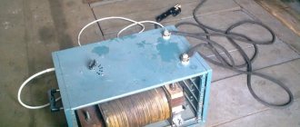
Almost every owner with the slightest bit of self-respect has a welding machine. As a rule, recently devices of relatively low quality have been purchased, which, after minor and inexpensive modifications, are absolutely not inferior to the best branded samples. One of these modifications is the installation of a choke for welding
.
What does this give? Firstly, the welding current is stabilized. When using an AC welding machine, ignition of the electrode is possible only when the voltage level required for ignition and the corresponding sinusoid of the electric current are reached. The inclusion of a choke in the design makes it possible to shift the phases between current and voltage, which leads to an easier start of welding work and more even combustion and, accordingly, a higher quality weld.
In modern construction, the floor plays one of the key roles, especially if it must have not only external characteristics, but also retain heat. Parquet flooring is considered the optimal solution. Parquet Kyiv has different types, colors and there are certain nuances in its choice.
Welding chokes
are used both in welding machines using electrodes and in semi-automatic machines. When used in a semi-automatic machine, metal spattering is significantly reduced, and the work becomes softer, and the seam is welded more deeply.
To make a welding choke with their own hands, craftsmen use transformers from old, preferably tube, televisions. To begin with, all the winding is completely removed, and the wire is wound onto the “hardware”, based on preliminary calculations.
It is worth noting that very good quality when making a welding choke with your own hands can be obtained if you use chokes from burnt out street lighting lamps as a workpiece. As a rule, the winding contains from 25 to 40 turns of wire, with a cross-section of 35-40 mm2 if aluminum wire is used and from 25 mm2 if it was possible to obtain copper wire. A bus bar, both aluminum and copper, is quite suitable for winding a choke.
So, you can install a choke on almost any welding machine, but experts still advise using it in conjunction with a rectifier unit - this only applies to welding machines operating with alternating current. In this case, a double goal is achieved. This results in softer operation and the ability to cook with any electrodes.
There are designs in which the choke is paired with a step-down transformer. In this case, the calculation of the throttle must be more accurate and is carried out using formulas that can be found in specialized literature.
With this implementation of the design, the preferred location for installing the choke is the secondary circuit of the welding transformer. It is worth noting that this is exactly how the choke is located in some expensive imported semi-automatic welding machines. The advantages here are obvious. With this arrangement, the transformer has normal dissipation and a very rigid external characteristic.
Adjusting the throttle is a very important task. Despite all the calculations, it is almost impossible to achieve stable and flawless operation the first time. Usually the number of turns is selected experimentally by unwinding or, conversely, adding turns. Another adjustment method is to change the air gap in the magnetic core - in this case the adjustment is smoother.
Purchasing a welding machine (inverter) is always associated with a dilemma: quality or price. And, as often happens, the price wins. By purchasing an inexpensive welding inverter, its owner receives a slight reduction in the quality of work with the unit. More precisely: difficulty with igniting the electrode and the rigidity of the welding process. But a small modification (and inexpensive) makes it possible to change the characteristics of the device. The easiest option is to install a throttle. What is it and what is the throttle for?
Its main purpose is current stabilization. The thing is that in an alternating current device, the consumables must be ignited at a certain voltage, which must correspond to the sinusoid of the electric current. The welding choke included in the inverter circuit allows you to shift the phases between voltage and electric current. And this, in turn, affects the ease of ignition of the electrode, plus a more even burning of the electric arc. In the compartment, the final result is an even and high-quality weld. This is what is required to confirm the quality of the final result.
Chokes can be installed in welding transformers, inverters, and semi-automatic machines. When using the device in semi-automatic welding machines, one can note a decrease in metal spattering, the seam is welded deeper, and the welding process is smoother.
Methods for adjusting current using a choke
The advantages of the device are undoubted. Practice confirms this completely. But there are three transformer modes it can be in. At the same time, using a choke in some of them, you can regulate the strength of the welding current. By the way, the inductor is connected to the secondary winding of the transformer, and the air gap in the core is adjusted.
- Idling. This is the mode when the device is turned on and no work is being done on it. Voltage is applied to the transformer, electromotive force is present in the secondary winding, but there is no welding current at the output.
- Load. An arc is ignited, which closes the electrical input circuit. It includes the inductor winding and the secondary winding of the transformer. A current flows through the circuit, the value of which is determined by the resistances of the two windings. If a choke was not installed in the circuit, then the output would produce a current of maximum value. And this is a high probability of getting burnt through the metals being welded and sticking of the electrode. The degree of current adjustment will depend on the air gap in the rod on which the inductor winding is wound.
- Short circuit. A short circuit is formed at the moment when the tip of the electrode touches the metal workpieces being welded. In this case, a magnetic flux of an alternating type is formed on the transformer core, and an electromotive force is induced on the secondary winding. In this case, the current strength will depend on the total resistance of the inductor winding and the secondary winding of the transformer.
As for the air gap, its increase leads to the fact that the chain resistance increases. And this, in turn, leads to a decrease in the magnetic flux, and accordingly the inductive resistance of the transformer and inductor windings decreases. The resistance has decreased and the output current has increased. Everything is according to Ohm's law. Therefore, the arc current increases. This is how the current of the welding arc can be controlled using a choke.
There is one drawback to this throttle system. Any welding machine vibrates during operation. This negatively affects the passage of current through the inductor coil. Therefore, you can abandon smooth tuning and current regulation, and switch to step tuning. To do this, there is no need to install an air gap in the throttle core. To do this, the winding of the device is made with taps (through a certain number of turns), to which contacts are soldered. However, it is necessary to take into account the fact that a current of several hundred amperes will pass through these contacts. Therefore, you need to choose ones that can withstand such current.
And one more reason why the throttle for the welding machine needs to be turned on so that the welding process takes place under “soft” conditions. There is a characteristic of the dependence of the welding arc voltage on the current strength at the end of the electrode, which is called falling. This is a very useful relationship, especially in cases where it is difficult or difficult to maintain the distance between the electrode and the metal workpieces being welded.
It is almost impossible to provide a falling characteristic with one transformer, because the resistance of its windings is insufficient. The inductor winding almost doubles the total resistance of the electrical circuit, which allows for a decreasing dependence of voltage on current. That is, this is another plus for the throttle. Now it becomes clear why this device is needed.
Rectifier for welding machine
Electrical circuit of a welding machine rectifier.
To weld with direct current, an AC-to-DC converter must be connected to the output winding of the transformer. Such a device is called a rectifier, which is why a welding machine with this device is called a rectifier.
The top graph represents the sinusoidal voltage at the output of the transformer secondary winding. The horizontal t-axis is the time axis. The time interval between zero voltage values is determined by the oscillation period. It consists of positive and negative half-cycles.
It can be seen that the current is not constant, but pulsating. The only way to reduce ripple is by increasing the capacitance of the capacitor.
To regulate the arc current, the choke must be connected between the transformer output and point 3 of the rectifier.
How to make a throttle with your own hands
For the choke coil, it is better to use a UI series magnetic core. Winding wire onto a reel is a difficult and time-consuming process that requires patience and accuracy. There are several points in this matter that determine the quality of the final result.
- Be sure to insulate the yoke UI before starting winding.
- Copper or aluminum wire can only be wound in one direction.
- Each layer wound on the core must be insulated from the next one. For which fiberglass, special cotton insulation or cardboard can be used.
- The insulating layer must be treated with bakelite varnish.
- If stepwise current regulation is arranged, then the winding terminals must be marked. This will simplify the subsequent connection of the choke to the welding machine, that is, the desired output will be easy to find.
Stepwise current regulation can also be achieved using a load ohmic resistance. Essentially, this is an ordinary spiral of nichrome wire that connects to the output of the inductor. However, it should be noted that this option is not the best. Nichrome wire gets very hot, sometimes even red hot, so this is a great danger.
In welding transformers, smooth current regulation is ensured by displacement of the primary winding relative to the secondary. By decreasing the distance between them, the magnetic field decreases. And, accordingly, a decrease in resistance in the circuit. Typically, transformer devices are equipped with a handle, which is located on top of the unit. By rotating the knob in one direction or the other, the arc current decreases or increases.
But for an inverter welding machine that is used in everyday life, it is better to use a choke to improve operation. Simpler, more convenient, inexpensive. Moreover, making it yourself is not a problem.
In its simplest form, a choke is a coil of thick copper wire wound around a magnetic core, which is connected to the output circuit of the welding machine in series with the electrode. A choke for a semi-automatic device is necessary to smooth out current ripples that occur during short-term changes in the input voltage and instantaneous short circuits on the electrode. When performing semi-automatic welding without this device, there is a high probability of weld defects occurring, since with such deviations in electrical parameters, the wire continues to feed at a constant speed.
Any home craftsman can make a choke for a semi-automatic machine. Its calculation is carried out in a very large scale (mainly in terms of wire cross-section), and the parameters of a homemade choke are selected by adjusting the core gap during trial activation of the semi-automatic device in different modes. However, it is still advisable to have at least a general understanding of the basic electrical principles underlying the operation of this device, as well as the design features of its manufacture.
The operation of the choke of a semi-automatic welding machine is based on the so-called “first law of switching”, according to which the current in the inductor cannot change instantly. In a very simplified form, we can say that the inductor acts as a kind of energy storage device, but unlike a capacitor, it accumulates not voltage, but current. When passing through the coil, the flow of electrons generates a magnetic field, the magnitude of which depends not only on the current strength, but also on the parameters of the core. By adjusting the gap between its elements, you can control the magnitude of the magnetic flux and thus regulate the inductive reactance of the inductor.
The inductance value of the inductor directly affects the rate at which the current increases during a short circuit. Moreover, it directly depends on the semi-automatic welding mode and the wire diameter. When using thin wire, a faster rise in current is required and, accordingly, less inductance than when using thick wire. For example, when the wire diameter is reduced by one and a half to two times, the inductance decreases by 2.5–3 times.
Chokes with 2.8mm ferrite cores
Also, a miniature inductor can be made by winding a wire on a small-sized ferrite core 400N, 600N with a diameter of 2.8 mm and a length of approximately 12...14 mm. The form for calculating a choke on a 2.8mm core is given below.
Rice. 4. Homemade chokes on ferrite cores with a diameter of 2.8 mm.
Using the above forms for calculating inductors, you can easily calculate and make a homemade inductor for your radio-electronic device.
Purpose of the throttle
Welding using a semi-automatic machine is carried out with direct current of negative polarity on a wire, the thickness of which varies within 0.5÷3.0 mm. The smaller its diameter, the lower the welding current and the more stable the arc. During the welding process, the molten wire metal enters the weld pool in the form of a continuous stream of droplets. This ensures the stability of the arc and the quality of the weld. With the short-term formation of a continuous flow of metal, a short-circuit current occurs, and in the event of a break, it sharply decreases. If a choke is included in the output circuit of a semiautomatic device, then in the first case it prevents an instantaneous increase in the current, and in the second case it compensates for the drop in its value due to the “stored” energy.
Semi-automatic welding machines use chokes with fixed, stepped (see figure above) or adjustable inductance. The first type is used when welding in constant modes, in the second case the choke is made with several taps, and in the third the inductance is regulated by changing the size of the gap in the magnetic core or mechanical movement of the core. With an unstable external power source, the best option for a semi-automatic machine is gap adjustment, since it allows you to experimentally select a welding mode with a stable arc and without metal spattering. And the optimal method for solving the problem of stability and quality of the welding process is to use a choke in a semi-automatic machine in combination with a voltage boost circuit on the input transformer.
Benefits of using a throttle
Single-phase bridge rectification circuit (a). Graphs of voltage and current in the transformer (b), voltage and current in the load (c).
A welding choke is a device for regulating the current used to perform welding work. The element is needed to compensate for resistance that may be lacking. It can be connected to the re-winding of the transformer structure. This makes it possible to shift the phases between the passing current and its voltage, as a result of which it is easier to ignite the electric arc at the beginning of work. It will burn evenly, and therefore it is possible to obtain a weld of good quality. If you do not use the choke, problems may occur during welding.
The choke may consist of a semi-automatic design or a welding device that involves the use of electrodes. A semi-automatic machine with a throttle practically does not splash metal during operation. The welding process will be much smoother than without a choke. The weld seam can be welded to a significant depth. The advantages of such an element are beyond doubt. It can be mounted not only on a homemade device, but also on a factory-made device. This is especially true for budget options that are prone to malfunctions. This can significantly facilitate work on such structures and improve the quality of the weld.
How to calculate the cross-section of a winding wire
To calculate the cross-section and select a suitable wire, it is first necessary to determine the maximum current density. Its value depends on the material of the conductor and the temporary operating mode of the semiautomatic device, which is determined by the passport value of the parameter PN (PV) - the duration of the load. The formula for calculating the current density based on the voltage value looks like this:
Here Jп is the current density in A/mm² for a given voltage value in percentage, and J is for long-term conditions.
For copper conductors of transformers and chokes, J is usually taken to be 3.5 A/mm².
When using aluminum wires, it is necessary to apply a reduction factor of 1.6 (see table).
To determine the wire cross-section (S) for winding the choke of a semi-automatic device, it is necessary to divide the rated value of the maximum current (I max) by Jп. For example, with I max = 150 A and PN = 40%, the cross-section of the copper wire will be equal to 27 mm². The exact type of conductor (wire or busbar) is selected from a reference book, rounded up.
The number of turns is calculated using a formula using the dimensions of the core, which are also determined by calculation. But craftsmen, as a rule, do not do all this, because they assemble a choke for a semi-automatic machine based on an existing magnetic circuit. The usual number of turns for such a product at a current of 150–200 A is several tens (40÷60). Unlike the cross-section size, the error here is not very critical. In the worst case, it may result in poor weld quality.
Materials for production
The choke for retrofitting a semi-automatic device or inverter can be assembled with your own hands, using structural elements from old equipment - tube TVs, old street lamps and other devices that have a transformer.
Structurally, it consists of a core made of a material that conducts a magnetic field, but does not conduct electric current, or is reliably insulated, and three layers of windings separated by a dielectric.
As a basis for the core, either a special material is suitable - ferrite, which has these properties, or a yoke (horseshoe) from an old transformer. Winding of the device for welding is done with aluminum or copper wire with a cross-section of 20-40 mm.
If aluminum is used, the wire cross-section must be at least 36 mm; copper wire can be thinner. A flat copper busbar with a cross-section of 8 mm is suitable.
The dimensions of the core should allow winding approximately 30 turns of a busbar of a given section, taking into account dielectric spacers. A core from the step-up transformer of the Soviet TV TCA 270-1 is recommended.
What is required for production
In order to make a choke for a semi-automatic machine with your own hands, first of all you should make the required calculations, and then prepare the necessary materials and tools. During the work you will need:
- soldering iron (from 100 W) with accessories;
- bench vice;
- pliers, pliers, hammer, etc.;
- coil core and body;
- getinax (or similar) for gaps;
- varnished cloth;
- keeper tape;
- epoxy or glue;
- copper or aluminum wire (or bar);
- two screw terminals.
In addition, you need a block to secure the reel body, as well as pieces of any plastic or wood to wedge it.
Step-by-step instructions for assembling a throttle with your own hands
To manufacture a welding choke, no diagrams or drawings are required. Everything is quite clear and obvious, you just need to know how many turns and what wire to wind. Any set of transformer iron can be used as a core, up to a package of rectangular plates. However, the best option would be to use a PL type core, since it is assembled from two monolithic C-shaped halves and the gaps between them can be used to adjust the inductance of the future inductor.
Such cores have been widely used and are used in power supplies for radio equipment since Soviet times. Therefore, finding an old transformer (for example, TC type) with a power of 200–300 W will probably not be a very difficult task. It is also very convenient for adjusting the gap that such a core is tightened with a special clamp with a screw connection (see figure below).
You can use any wire or bar (but copper is still better), the main thing is that the cross-section corresponds to the design one.
Winding and installing the choke
When disassembling an old transformer, you must very carefully remove the coils, free them from the wires and clean the junction of the core halves until shiny. The following sequence of actions looks like this:
- Place the reel on a wooden block, secure it with a vice and wrap one or two layers of keeper tape around the reel, and varnished cloth on top of it. Then carefully wind the first layer of wires, turn by turn (you will get about 8–12 turns, depending on the thickness and gaps). You must act very carefully, because the wires are hard, and the coil is made of thin and fragile getinax.
- Wrap varnished fabric over the first layer of turns, having previously coated it with varnish. The classic option is bakelite varnish, but you can use any other one, for example parquet. Wind a second layer of turns, also cover it with varnish and varnish. Carefully bend the output end.
- Do the same with the second coil, then dry both of them thoroughly. Prepare two plates of getinax (or other insulating plastic) 1–2 mm thick according to the size of the joint of the core halves.
- Place both coils on one of the core halves, place insulating pads and insert the other half. Carefully tighten the core with a clamp.
- Connect the coils in series by twisting with soldering or a screw (pre-tinned), and then insulate the connection point.
- Fix the ends of the coils intended for connection on the clamp, and then solder the terminals to them.
When checking a choke with a semi-automatic device, you need to try it in different modes, and, depending on the situation, increase or decrease the inductance by replacing the gaskets in the core gap.
In the famous book by V. Ya. Volodin “Modern do-it-yourself automatic welding machines,” a classic calculation of the number of turns in the inductor winding is given. For a home craftsman, a more simplified version of determining the number of turns would be suitable, even if their number is approximate. If anyone knows sources with such techniques or can describe how to do it themselves, please share them in the comments to the article.
There are a lot of inexpensive semi-automatic welding machines on the market that will never work properly because they were made incorrectly from the start. Let's try to fix this on a welding machine that has already fallen into disrepair.
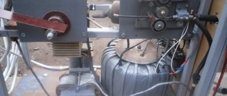
I came across a Chinese Vita semi-automatic welding machine (from now on I will simply call it PA), in which the power transformer burned out; my friends just asked me to repair it.
They complained that when they were still working, it was impossible for them to cook anything, there were strong splashes, crackling, etc. So I decided to bring it to a conclusion, and at the same time share my experience, maybe it will be useful to someone. Upon first inspection, I realized that the transformer for the PA was wound incorrectly, since the primary and secondary windings were wound separately; the photo shows that only the secondary remained, and the primary was wound next to it (that’s how the transformer was brought to me).
This means that such a transformer has a steeply falling current-voltage characteristic (volt-ampere characteristic) and is suitable for arc welding, but not for PA. For Pa, you need a transformer with a rigid current-voltage characteristic, and for this, the secondary winding of the transformer must be wound on top of the primary winding.
In order to start rewinding the transformer, you need to carefully unwind the secondary winding without damaging the insulation, and cut off the partition separating the two windings.
For the primary winding I will use 2 mm thick enamel copper wire; for complete rewinding we will need 3.1 kg of copper wire, or 115 meters. We wind turn to turn from one side to the other and back. We need to wind 234 turns - that’s 7 layers, after winding we make a tap.
We insulate the primary winding and taps with fabric tape. Next we wind the secondary winding with the same wire that we wound earlier. We wind tightly 36 turns, with a shank of 20 mm2, approximately 17 meters.
The transformer is ready, now let's work on the choke. The throttle is an equally important part in the PA, without which it will not work normally. It was made incorrectly because there is no gap between the two parts of the magnetic circuit. I will wind the choke on iron from the TS-270 transformer. We disassemble the transformer and take only the magnetic circuit from it. We wind a wire of the same cross-section as on the secondary winding of the transformer on one bend of the magnetic circuit, or on two, connecting the ends in series, as you like. The most important thing in the inductor is the non-magnetic gap, which should be between the two halves of the magnetic circuit; this is achieved by PCB inserts. The thickness of the gasket ranges from 1.5 to 2 mm, and is determined experimentally for each case separately.
Those craftsmen who are interested in welding work have often thought about how to build an installation for pairing elements and parts. The homemade semi-automatic welding machine described below will have the following technical characteristics: mains voltage equal to 220 V; power consumption level not exceeding 3 kVA; works in intermittent mode; the adjusted operating voltage is stepwise and varies between 19-26 V. The welding wire is fed at a speed ranging from 0 to 7 m/min, while its diameter is 0.8 mm. Welding current level: 40% PV - 160 A, 100% PV - 80 A. Practice shows that such a semi-automatic welding machine is capable of demonstrating excellent performance and a long service life.
Power on and check
The choke for welding is connected to the system between the diode bridge and ground - a contact that connects to the material being welded. The output of the diode bridge is connected to the input of the inductor, to the output of the assembled inductor - respectively, a ground contact.
The entire assembly for welding must be tested on a piece of metal of the same chemical composition and thickness with which it is planned to carry out most of the welding work in the future. Quality indicators are:
- easy electric ignition;
- arc stability;
- relatively weak crackling sound;
- smooth combustion without strong splashes of melt.
Please note that the introduction of this element into the design of the welding machine leads not only to stabilization of operation, but also to a slight drop in current strength . If the inverter or semiautomatic device begins to cook worse, it means that the current strength has dropped.
The choke needs to be disconnected and a few turns removed from each coil. The exact number of turns in each specific case is selected empirically.
Preparing elements before starting work
As a welding wire, you should use a regular one, one that has a diameter within 0.8 mm, it is sold in a 5 kg reel. It will be impossible to manufacture such a semi-automatic welding machine without a 180 A welding torch, which has a Euro connector. You can purchase it in a department specializing in the sale of welding equipment. In Fig. 1 you can see a diagram of a semi-automatic welding machine. For installation you will need a power and protection switch; you can use a single-phase AE circuit breaker (16A) for it. When the device is operating, there will be a need to switch between modes; for this you can use PKU-3-12-2037.
You can dispense with the presence of resistors. Their goal is to quickly discharge the inductor capacitors. As for capacitor C7, in tandem with a choke it is capable of stabilizing combustion and maintaining the arc. Its smallest capacity can be 20,000 microfarads, while the most suitable level is 30,000 microfarads. If you try to introduce other types of capacitors that are not so impressive in size and have a larger capacity, then they will not prove to be sufficiently reliable, since they will burn out quite quickly. To make a semi-automatic welding machine, it is preferable to use old-type capacitors; they need to be arranged in the amount of 3 pieces in parallel. Power thyristors for 200 A have sufficient reserve; it is permissible to install them at 160 A, however, they will operate at the limit, in the latter case there will be a need to use quite powerful fans during operation. The B200 used should be mounted on the surface of an oversized aluminum base.
↑ Diagram and details of the welder
A single-phase 16A type AE circuit breaker is used as a power and protection switch. SA1 - welding mode switch type PKU-3-12-2037 with 5 positions.
Read also: Saw calm stalls when you press the gas
Resistors R3, R4 are PEV-25, but they don’t have to be installed (I don’t have them). They are designed to quickly discharge choke capacitors.
Now for capacitor C7. Paired with a choke, it ensures combustion stabilization and arc maintenance. Its minimum capacity should be at least 20,000 microfarads, optimal 30,000 microfarads. Several types of capacitors with smaller dimensions and higher capacity were tried, for example CapXon, Misuda, but they did not prove to be reliable and burned out.
Power thyristors for 200A are taken with a good margin. You can install it at 160 A, but they will work at the limit, and you will need to use good radiators and fans. The used B200s stand on a small aluminum plate.
Relay K1 type RP21 for 24V, variable resistor R10 wirewound type PPB.
When you press the SB1 button on the burner, voltage is supplied to the control circuit. Relay K1 is activated, thereby, through contacts K1-1, voltage is supplied to the electromagnetic valve EM1 for acid supply, and K1-2 - to the power supply circuit of the wire drawing motor, and K1-3 - to open the power thyristors.
Switch SA1 sets the operating voltage in the range from 19 to 26 Volts (taking into account the addition of 3 turns per arm up to 30 Volts). Resistor R10 regulates the supply of welding wire and changes the welding current from 30A to 160A.
When setting up, resistor R12 is selected in such a way that when R10 is turned to minimum speed, the engine still continues to rotate and does not stand still.
When you release the SB1 button on the torch, the relay releases, the motor stops and the thyristors close, the solenoid valve, due to the charge of capacitor C2, still remains open, supplying acid to the welding zone.
When the thyristors are closed, the arc voltage disappears, but due to the inductor and capacitors C7, the voltage is removed smoothly, preventing the welding wire from sticking in the welding zone.
Winding the transformer
When making a semi-automatic welding machine with your own hands, the process must begin with winding the OSM-1 transformer (1 kW).
It will initially have to be completely disassembled; the iron should be put aside for a while. It is necessary to make a coil frame using textolite with a thickness of 2 mm; this need arises for the reason that its frame does not have a sufficient margin of safety. The dimensions of the cheek should be 147x106 mm. You need to prepare a window in the cheeks, the dimensions of which are 87x51.5 mm. At this point we can assume that the frame is completely ready. Now you need to find a Ø1.8 mm winding wire; it is preferable to use one that has reinforced fiberglass protection.
When making a semi-automatic welding machine with your own hands, you need to create the following number of turns on the primary winding: 164 + 15 + 15 + 15 + 15. In the gap between the layers you need to lay insulation using thin fiberglass. The wire must be wound with maximum density, otherwise it may not fit.
To prepare the secondary winding, you need to use an aluminum busbar, which has glass insulation with dimensions equal to 2.8x4.75 mm; it can be purchased from winders. You will need about 8 m, but you need to purchase the material with some reserve. Winding should begin with the formation of 19 turns, after which you need to provide a loop directed under the M6 bolt, then you need to make another 19 turns. The ends should have a length of 30 cm, which will be needed for further work. When making a semi-automatic welding machine, you should take into account that if you may not have enough current at such a voltage to work with dimensional elements, then at the installation stage or during the further use of the device you can remake the secondary winding, adding three more turns to it per arm, in the end result this will give you 22+22.
A semi-automatic welding machine must have a winding that fits end to end, for this reason it should be wound very carefully, this will allow everything to be positioned correctly. When using enamel wire to form the primary winding, it is then necessary to carry out treatment with varnish; the minimum time the coil is held in it is limited to 6 hours.
Now you can mount the transformer and connect it to the electrical network, which will allow you to determine the no-load current, which should be approximately 0.5 A, the voltage level on the secondary winding should be equivalent to 19-26 V. If the conditions match, you can put the transformer aside for a while and proceed to the next stage.
When making a semi-automatic welding machine with your own hands, instead of OSM-1 for a power transformer, it is permissible to use 4 units of TS-270, however, they have slightly different dimensions; if necessary, for this case, you can independently calculate the data for winding.
How to wind a choke for a welding machine - Metalworker's Guide
Almost every master has at least once thought about how to make a choke for a welding machine with his own hands.
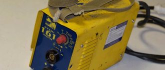
Today, a fairly large number of different devices are sold that can be used in small-scale production.
This can be a device that operates on temporary or continuous current, a semi-automatic welding machine, or a product using electrodes. However, a high-quality device is very expensive, and budget analogues quickly become unusable.
Diagram of an AC welding machine with a separate choke: 1 – primary winding, 2 – core, 3 – secondary winding, 4 – choke winding, 5 – fixed part of the choke core, 6 – moving part of the choke core, 7 – screw pair, Dr – regulator current.
To assemble a homemade welding fixture, you will need to select and build all the necessary elements, including the throttle.
Principle of operation
The main property of an inductor, which is a magnetic circuit wound under certain conditions around a ferromagnetic core, is the stabilization of current strength over time.
Simply put, voltage applied to the coil causes a smooth increase in current output. Changing the polarity leads to the same smooth decrease in current.
The main factor is the condition that the current passing through the inductor cannot sharply increase or decrease. This is precisely what determines the value of using a choke for welding - resistance compensation allows you to avoid sudden jumps in amperage.
This allows you to protect against accidental burning of the workpieces being welded, reduce spattering of the melting metal and accurately select the current parameters for welding for a given metal thickness. The chances of getting a good weld using a welding choke are much higher.
The parameter that determines the current change coefficient is inductance. It is measured in H (henry) - in 1 second at a voltage of 1 V, only 1 A can pass through a choke with an inductance of 1 H.
The number of turns on the coil directly affects the amount of inductance. It is directly proportional to the number of turns squared. But if you need to make a welding choke with your own hands, then it is not necessary to calculate the exact number of turns.
Since the parameters of welding machines for household use are mostly standard and well-known, a welder will only need to use the instructions below to make a choke with his own hands.
Purpose
In an inverter for welding, a choke is needed to create an electric arc on the electrode. Ignition occurs when a certain voltage level is reached.
The welding choke increases the resistance, which shifts the phases between current and voltage and allows for smoother ignition. This fact in itself often allows one to avoid burning through the workpiece, especially if parts made of thin sheet metal are welded.
A smooth change in current makes it possible to avoid damaging the workpiece by abruptly applying too much power, to optimally set the arc temperature and, accordingly, to prevent metal spattering while maintaining the required processing depth.
Another valuable property is its partial protection against unstable voltage in the network.
A choke for a welding inverter greatly facilitates ignition of the electrode, which should light up at a higher voltage than the inverter produces.
An example is the MP-3 electrode, which must have a voltage of 70 V to ignite. An output choke for welding can make working with this electrode much easier for an inverter, which produces only 48 V at idle.
This occurs due to the phenomenon of self-induction. The device induces EMF (electromotive force), which causes air breakdown and flashing of the welding arc, as soon as you bring the additive a few millimeters from the metal surface.
The choke for welding is connected to the secondary winding of the transformer in the machine. It can be used in devices of any type - both home-made and factory-made, operating on any principle - inverter, with a step-down transformer, and the like.
Materials for production
The choke for retrofitting a semi-automatic device or inverter can be assembled with your own hands, using structural elements from old equipment - tube TVs, old street lamps and other devices that have a transformer.
Structurally, it consists of a core made of a material that conducts a magnetic field, but does not conduct electric current, or is reliably insulated, and three layers of windings separated by a dielectric.
As a basis for the core, either a special material is suitable - ferrite, which has these properties, or a yoke (horseshoe) from an old transformer. Winding of the device for welding is done with aluminum or copper wire with a cross-section of 20-40 mm.
If aluminum is used, the wire cross-section must be at least 36 mm; copper wire can be thinner. A flat copper busbar with a cross-section of 8 mm is suitable.
The dimensions of the core should allow winding approximately 30 turns of a busbar of a given section, taking into account dielectric spacers. A core from the step-up transformer of the Soviet TV TCA 270-1 is recommended.
Sequencing
When the necessary tools and materials are prepared, you can begin to manufacture the throttle for welding. The algorithm of actions is as follows:
- disassemble the transformer, clean the coils from traces of old windings;
- make gaskets from fiberglass, cardboard impregnated with bakelite varnish, or other suitable dielectrics, which will subsequently play the role of an inductive (air) gap. They can simply be glued to the corresponding surfaces of the coils. The thickness of the gasket should be 0.8-1.0 mm;
- wind a thick copper or aluminum wire onto each coil. You should focus on a round wire made of aluminum with a cross-section of 36 mm or copper with a similar ohmic resistance. Each “horseshoe” is covered with 3 layers of 24 turns each;
- lay a dielectric material between the layers - fiberglass, cardboard impregnated with bakelite varnish or another dielectric. The gaskets must be reliable, since a choke of this design is prone to self-breakdown between windings. If the resistance between the windings is lower than the air resistance between the electrode and the additive, then a breakdown will occur between the windings, and the welding device will be irreversibly damaged.
Winding must be done evenly, without overlaps, strictly in the same direction, so that the “bridge” between the coils is on one side of the future inductor, and the input and output contacts are on the other.
In case of an error, the jumper can also be installed askew. It is important that its installation turns coils with different winding directions into coils with the same direction in fact.
Power on and check
The choke for welding is connected to the system between the diode bridge and ground - a contact that connects to the material being welded. The output of the diode bridge is connected to the input of the inductor, to the output of the assembled inductor - respectively, a ground contact.
The entire assembly for welding must be tested on a piece of metal of the same chemical composition and thickness with which it is planned to carry out most of the welding work in the future. Quality indicators are:
- easy electric ignition;
- arc stability;
- relatively weak crackling sound;
- smooth combustion without strong splashes of melt.
Please note that the introduction of this element into the design of the welding machine leads not only to stabilization of operation, but also to a slight drop in current strength . If the inverter or semiautomatic device begins to cook worse, it means that the current strength has dropped.
The choke needs to be disconnected and a few turns removed from each coil. The exact number of turns in each specific case is selected empirically.
Choke winding
To wind the inductor, use a 400 W transformer, enamel wire Ø1.5 mm or larger. Winding must be done in 2 layers, laying insulation between the layers, and the requirement must be observed, which is the need to lay the wire as tightly as possible. Now you have to use an aluminum bus with dimensions of 2.8x4.75 mm, when winding you need to carry out 24 turns, the rest of the bus should be 30 cm. The core should be mounted with a gap of 1 mm, in parallel with this the textolite blanks will have to be laid. When making a semi-automatic welding machine yourself, it is permissible to wind the choke on iron borrowed from an old tube TV. You can use a ready-made transformer to power the circuit. Its output should be 24 V at 6 A.
Formula for calculation
In most cases, very precise inductor inductance is not a critical factor, so a coreless inductor can be wound on the body of the MLT resistor. In order to calculate the required number of turns, you can use the formula:
N=32*SQRT(L/d)
Where:
- N is the required number of turns,
- L is the required inductance of the inductor in μH,
- d is the diameter of the frame (in this case, the resistor frame) in mm.
SQRT is the square root of a number function.
To make calculations, you can use our online calculator:
Housing assembly
At the next stage, you can begin assembling the installation body. To do this, you can use iron, the thickness of which is 1.5 mm; the corners must be connected by welding. It is recommended to use stainless steel as the base of the mechanism.
The role of the motor can be the model that is used in the windshield wiper of a VAZ-2101 car. It is necessary to get rid of the limit switch, which works to return to the extreme position. The bobbin holder uses a spring to obtain braking force; for this, you can use absolutely any one that is available. The braking effect will be more impressive if it is influenced by the compressed spring, for this you have to tighten the nut.
In order to make a semi-automatic machine with your own hands, you need to prepare the following materials and tools:
- enamel wire;
- wire;
- single-phase machine;
- transformer;
- welding torch;
- iron;
- textolite
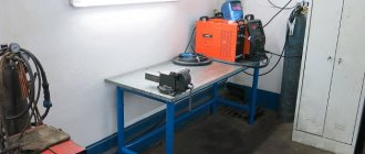
Making such an installation will be a feasible task for a craftsman who has familiarized himself with the recommendations presented above in advance. This machine will be much more profitable in terms of cost compared to the model that was produced at the factory, and its quality will not be lower.
Throttle application
A choke for DIY welding works best on welding transformers. Our practice proves this. The choke quickly ignites the arc even with a significant loss of current, so it can be used without problems in the country or in a workshop with unstable voltage.
A separate feature is the ability to use a choke in conjunction with a rectifier. The inductor + rectifier combination is capable of increasing the electromotive force of self-induction. In the case of a semi-automatic machine, such a set of equipment allows you to easily ignite an arc even at a considerable distance from the metal surface.