Types of welding machines
To make a welding machine with your own hands, you need to delve into the essence of the issue and choose one scheme to implement your plan, and then start purchasing components.
Depending on certain parameters, it is customary to distinguish between the following types of units:
- On alternating current.
- On direct current.
- Three-phase.
- Inverter.
The first type listed in the list is considered the simplest; if you want to create a second version of the device, you need to introduce a special block and an anti-aliasing filter into the design.
Three-phase models can be found in industry; it is irrational to choose such units for home use.
Advice! The inverter type is a more complex device; without basic knowledge of board assembly and understanding of circuits, professionals do not recommend attempting to create it yourself.
Scheme
One of the first steps in manufacturing an inverter is determining its operating circuit. Since there is a large amount of choice on the Internet, there is no need to come up with something new.
We will continue to use information about the inverter model COLT1300 as a basis; the working diagram is shown in Figure 1:
Fig 1.
Figure 2 shows a diagram of the control unit for the processes taking place in the power section. For the type of device under consideration, the circuits are squeezed onto one board. Let's change this and make the control unit on a separate board.
Fig.2
Let's divide the main diagram into several parts and get:
Power section and transistor drivers:
Power supply:
Welding inverter with spike controller:
Inverter power supply:
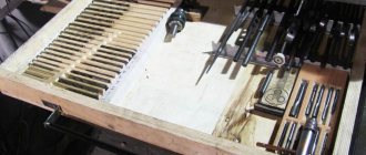
To make electrical 4 boards, you will need the following:
- textolite FR4 150×250mm (2mm);
- permanent black marker;
- citric acid and hydrogen peroxide;
- soldering flux LTI-120;
- drill with a diameter of 1mm and 2mm;
In the Dip Trace program we draw a power circuit:
Convert to payment:
At the end you will get a drawing:
An example is shown in a simpler diagram. You can download a tutorial for working with Dip Trace on the Full-Chip.net website. It sequentially describes each operation for printing microcircuits.
The resulting image of the layout must be printed on a laser printer, this is a prerequisite, ink will not give the desired effect:
- Let's prepare the textolite. Sand lightly with fine-grit sandpaper to a bright surface. We attach the printed layout to the plate and wrap it with another layer of newsprint on top.
- Apply a hot iron and wait 15-20 seconds. Let it cool gradually, then soak it in water to make it easy to peel off. If in some area the connection is poorly printed, we fill it in with a black marker.
- Preparing a bath for etching the board. The solution includes citric acid, hydrogen peroxide and water. The container is large enough for the board to fit completely into it. You must be careful with this mixture and wear rubber gloves. Stir only with wooden objects, not metal ones.
- Then all this should be placed in a warm place or in a basin with warm water. By controlling the process, you can see when the unpainted copper coating comes off, then you can remove the part.
- Dry the diagram and remove the marker with sandpaper. We cover the surface with LTI-120 flux. In order to allow the tracks to oxidize, they must be carefully polished to a pleasant shine.
So, we get two boards for the power circuit and the control unit.
List of materials and tools
When carefully familiarizing yourself with the design of a welding machine operating on alternating current, you need to know that such samples have a primary winding of 220 volts, and on the secondary winding it drops to 50-60 volts, after which it goes to the electrode in contact with the workpiece.
Before you begin assembling the equipment, you should prepare or purchase the following items:
- Magnetic core.
- Cable for coil winding.
- Materials for insulating connections.
Experts consider the factory transformer to be the most versatile workpiece; some parts are perfect for making simple models yourself. We are talking about a magnetic circuit and a primary winding, but when such components are not available, the element must be created from scratch.
Secondary winding
For the secondary winding you can use copper or aluminum. The wire can be either single-core or consisting of several conductors. Section from 10 to 24 square millimeters.
It is very convenient to wind the coil separately from the core, for example, on a wooden blank, and then assemble transformer steel plates into a finished, reliably insulated winding.
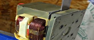
Microwave power supply
The considered welding machine circuit after assembly should produce a minimum of 4 kW; if we take the element from a microwave oven, which has a rating of 1.2 kW, as the main part, it will not be enough.
For operation, two transformers should be selected, which will subsequently need to be connected to each other.
The detailed algorithm of actions looks like this:
- By powering two parts to a 220-volt network, the integrity of the winding is checked.
- To remove the high-voltage winding, you need to cut the magnetic core.
- The coil is removed from the chain.
- From a copper bus of 10 sq. mm the core is manufactured.
- A dielectric spacer is created under the primary winding.
- The coil and magnetic circuit are connected.
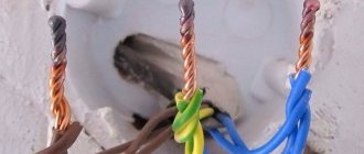
- All cables are connected in accordance with the diagram.
After installing the electrode in the holder, you can begin to check the functionality of the created unit; there is no need to take markings with a diameter of more than 4-5 mm.
Diagnostics of a homemade inverter and its preparation for operation
Assembling a homemade welding inverter is not the whole process. The preparatory stage is also considered an important part of the entire work, where it is necessary to check whether all its systems are working correctly and how to configure the necessary parameters.
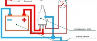
First of all, equipment diagnostics are carried out, namely, supplying a voltage of 15 volts to the controller and cooling system of the welding machine in order to check their endurance. Thanks to this, the functionality of the mechanisms is checked and the avoidance of overheating during operation of the unit.
When the capacitors in the unit are fully charged, a relay is connected to the electrical network, which is responsible for closing the resistors. With direct supply, without a relay, there is a risk of the device exploding.
When the relay is functioning, voltage is supplied to the device for up to 10 seconds. It is quite important to find out how long the inverter can function during welding. To do this, it is tested for 10 seconds. If the radiator remains at the same temperature, then the time can be set to 20 seconds, etc. up to a full minute.
DC equipment
People who professionally repair welding machines can confidently call this model more stable when considering the characteristics of the arc. An auxiliary component is responsible for the process of voltage transfer, which is known to many as a converter, supplemented by a smoothing element.
With such a device, you can weld not only the usual type of metal, but also cast iron or stainless steel, since the seam is as smooth and neat as possible.
- Before starting assembly, you will need to purchase powerful diodes or transistors in the amount of 4 pieces, each copy must have a rating of 200 A.
- The design includes a capacitor with a capacity of 15 thousand uF and a choke; when working independently, you should be guided by a special circuit.
Important! During operation of the transformer, overheating may occur, which will lead to rapid failure of the diodes; to prevent this excess, the structure is equipped with a device for heat removal.
Types of welding
First you need to understand what kind of welding we are making the machine for. The following types of welding are distinguished:
- Electric arc;
- Microarc;
- Point pulse (contact);
- Gas.
Arc welding
It uses an industrial frequency of 50-60 hertz, as well as a direct current of 200 amperes. You can weld a fence, garage and other fairly serious structures.
Micro arc welding
Used when laying wiring, as well as when repairing it.
Spot pulse or resistance welding
Used in the manufacture of products from thin steel sheets.
Gas welding
It is such a serious process that there is no point in making such a device at home. It's easier and cheaper to buy it. Moreover, it is impossible to make gas cylinders for it at home.
Making a gas generator at home is dangerous; if something goes wrong, an explosion may occur.
Unit with small dimensions
A well-assembled inverter welding machine is no less useful both in production and at home when repairing cars or small items.
Thanks to this type of device, it is possible to implement spot welding, which in some situations will be much more convenient, besides, the weight and dimensions of the box are quite compact, it can be easily carried by hanging it on your shoulder.
The design includes:
- Diode rectifier.
- Management system.
- Power part.
- Diode and choke.
- Cooler for cooling.
- Feedback to control parameters.
When creating a model, you will need to wind a power transformer yourself, the base of which will be a ferrite ring. Professionals advise purchasing a ready-made assembly of semiconductor elements for the bridge; some components cannot be found at home; they are often ordered or bought in specialized stores.
The device is considered quite complex; without self-confidence, suitable circuits and basic skills, you should not undertake the process.
Having started to implement their plans, many owners noticed that independently constructing an inverter model is no cheaper than factory products, so it is most rational to buy a ready-made unit with specified operating parameters.
Video instructions will be no less practical; thanks to them, you will be able to understand all the stages of work on creating equipment much faster.
Manufacturing a resonant inverter
As a basis, you need to use an AT form factor computer power supply, which will require a cooler and radiators. Parts are taken from the basic base of monitors and televisions, otherwise, if they are not available, they are bought on the market. All components are low cost.
Manufacturing recommendations:
- To simplify the circuit, PWM is completely eliminated, since it will require a stabilized voltage received by the master oscillator.
- Use KC213 zener diodes to prevent transistor failure.
- To reduce interference and interference, it is necessary to install high-frequency power transistors next to the transformer.
- The tracks for the power bridge and power block on a board made of thick PCB (at least 4 mm) must be made wider (currents flow up to 30 A) and tinned with refractory solder (at least 2 mm).
- Use at least 3 squares for the
- Use double insulation (fireproof mica or fiberglass casings) for high-voltage circuits.
- The throttle must be without a metal casing.
- Good constant ventilation.
- Power diodes (output) must be protected from breakdown using an RC circuit.
Then you need to decide on the parameters of inverter welding with your own hands. It is also possible to use the following characteristics:
- Output load current: from 5 to 120 A.
- Voltage (idle): 90 V.
- The duration of the load may vary. It all depends on the diameter of the electrode: 2 mm = 100%, 3 mm = 80%. The influence of high temperature must be taken into account.
- Input current: about 10A.
- Approximate weight: about 3 kg.
- There must be a current regulator when welding.
- Type of current-voltage characteristic ensuring operation in semi-automatic mode: falling.
Equipment diagram
The main part, the master oscillator, is assembled on the SG3524 microcircuit, which is used in all uninterruptible power supplies. The inverter has a low power consumption of about 2.5 kW, making it possible to use in an apartment.
The transformer must be assembled on E42 type cores, which are used in old lamp monitors. For production you need approximately 5 pieces of such transformers.
Another transformer should be used for the choke. The remaining inductance elements are assembled from a 2000NM type core. Diodes and transistors must be installed on radiators with KTP-8 or another type of thermal paste. The open circuit voltage is approximately 36 V with a long arc of 4 to 5 mm, which allows novice builders to work with it. The output cables should be laid in ferrite tubes or ferrite rings of the power supply.
A design feature of the circuit is the occurrence of a maximum current in winding I during resonance.
Scheme 1 - Scheme of a welding resonant inverter
Thanks to its low weight and dimensions, it becomes possible to modernize the device.
Preventing Electrode Sticking
For this case, the IRF510 transistor, which is a field effect transistor, is used. In addition, it also provides soft start and input interruption on the SG3524 chip:
- When the temperature is high, the temperature sensor is triggered.
- Switch off using a toggle switch.
- Blocking in case of short circuit (short circuit).
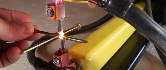
Photo of a homemade welding machine
Share with friends
Self-assembly costs
This section provides a calculation of the funds invested in the assembly of the welding inverter.
The list shows the main pieces of equipment. Anything not included in the list is of little importance. The price, on the contrary, is indicated for one unit:
- thermal conductive paste – KPT-8 200r;
- ferrite core – 170r;
- wire coil - PETV d=1.5 for transformer winding 550r;
And a list of parts:
- power diodes VS-150 EBUO4 390r-1pcs;
- transistors IRG4PC50UDPBF IGBT 600V 55A 60kHz 230-1pcs;
- high-speed PWB controller for switching power supplies UC3825N 300r-1pcs;
- Finder soft start relay, in steps of 3.5 16A 250V 70r;
- power resistor SQP3BT 47 Ohm 9p;
- EMI suppression filter B82731-N2102-A20 57р;
- capacitors 470mKf 450V series LS 35×45 770r-1pcs;
- radiators Hs 113-50 50x85x24 180r-1pcs;
- fan DEEPCOOL WIND BLADE 80, 80mm 260r;
- diode bridge KTs405 90-92 27r;