If you have the necessary plumbing and electrical installation tools (we will talk about them in detail below), and you have the appropriate professional skills, then you can quite make it DIY welding transformer.
You will, of course, have expenses, but they will be incomparably lower compared to the costs of purchasing a factory-made gadget. But how much pleasure you will get in the process of your favorite homemade work. And the delight at the moment of successful start of electric welding is, in general, incomparable!
In this article we will give you a lot of useful advice on choosing, calculating and manufacturing a welding transformer (hereinafter referred to as ST), which will help you optimize costs and save your budget.
A properly made device with your own hands is no worse than a factory one.
Appearance of a homemade welding transformer. East. https://autokuz.ru/kuzovnoy-remont/kak-sdelat-svarochnyj-apparat-svoimi-rukami.html.
The article will talk about two types of welding transformers. For welding:
- arc;
- contact
DIY welding transformer: what we need
The range of tools and equipment for the manufacture and assembly of both types of ST is identical. We will need the following:
- electrical voltage indicator . To control the absence of the latter on electrical contacts, and thereby ensure safety when performing electrical installation work;
- Angle grinder (aka “grinder”, “whip-machine”, etc.) with a set of discs (cutting, grinding, etc.);
- electric drill with a set of metal drills and a core;
- AC tester or voltmeter
- any " scriber ". Used for marking on metal;
- metalwork clamps . For fixing parts when marking “in place”;
- set of power tools . The specific composition of the kit depends on the materials that will be used in the manufacture of the ST. In general, it is like this: a complete electric soldering iron. We will perform soldering using POS-40 solder;
- screwdrivers (various sizes with straight and Phillips slots);
- wrenches: wrenches;
- caps;
- end;
It is more convenient to carry out all work on a bench with an electrical insulating coating, equipped with a bench vice.
To manufacture a transformer, components and materials are required that differ depending on the type of transformer. In general, the following is required:
- protective casing . Must provide: protection from electric shock;
- exclude the possibility of any objects getting inside the gadget;
Important : PVC insulating tape cannot be used, because it is destroyed when heated.
Homemade welding transformer for arc welding
Recommendation : read the material “Welding transformer: device and operating principle”
Before you begin further work on the manufacture of CT, you should decide what exactly you will create. You need:
- choose the design and electrical circuit diagram of the future device;
- carry out electrical and, if necessary, structural calculations of its parameters.
Only after this should you select the necessary equipment, materials and prepare, if necessary, special tools.
How to calculate a welding transformer. Scheme
The question of how to calculate a homemade welding transformer is very specific, since it does not correspond to standard diagrams and generally accepted rules. The fact is that when making homemade products, the parameters of their components are “adjusted” to the components already available (mainly to the magnetic circuit). Moreover, it often happens that:
- transformers are not assembled from the best transformer iron;
- the windings are wound with not the most suitable wire and many other negative factors.
As a result, homemade products heat up and “hum” (the core plates vibrate at the frequency of the mains: 50 Hz), but at the same time they “do their job” - weld metal.
Based on the shape of the cores, transformers are classified into the following main types:
- core;
- armored.
Types of core. East. https://v277.ru/svarka/65-svarochnyj-transformator.
Explanations for the picture:
- a – armored;
- b – rod.
Rod- transformers , compared to armor- type transformers, allow higher current densities in the windings. Thanks to this, they have a higher efficiency, but the labor intensity of their production is much higher. However, they are used more often.
On the rod core, the winding circuits shown in the figure are used.
Explanations for the picture:
- a – network winding on both sides of the core;
- b – the corresponding secondary (welding) winding, connected in counter-parallel;
- c – network winding on one side of the core;
- d – the corresponding secondary winding, connected in series.
For example, let’s calculate the ST assembled according to the “c” – “d” scheme. Its secondary winding consists of two equal parts (halves). They are located on opposite shoulders of the magnetic circuit, and are connected in series to each other. Calculations consist of determining the theoretical and selecting the actual dimensions of the magnetic circuit.
We determine the CT power (based on the current in the secondary winding) from the following considerations. For electric welding in everyday life, coated electrodes Ø, mm: 2, 3, 4 are most often used. We choose the “golden mean” for the most popular ones - 120...130 A. CT power is determined by the formula:
P = Uх.х. × Ist. × cos(φ) / η, where:
- Uх.х. – open circuit voltage;
- Ist. – welding current;
- φ – phase angle between voltage and current. We accept: cos(φ) = 0.8;
- η – efficiency. For homemade ST: efficiency = 0.7.
If you calculate the magnetic core according to the reference book, then its cross-section for the selected current is 28 sq.cm. In practice, the cross-section of the magnetic circuit for the same power can vary within the range: 25...60 sq.cm.
For each section, it is necessary to determine (using a reference book) the number of turns of the primary winding to ensure the specified output power. We will only note that the larger the cross-sectional area of the magnetic circuit (S), the fewer turns of both coils will be needed. This is an important point, since a large number of turns may not fit into the “window” of the magnetic circuit.
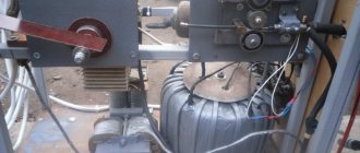
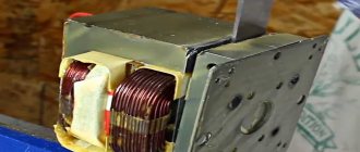
It is possible to use the magnetic circuit of an old transformer (for example, from a microwave oven, of course, after some reconstruction of it - replacing the secondary winding).
Old transformer. East. https://strgid.ru/mozhno-li-sdelat-svarochnyi-apparat-svoimi-rukami-chto-nuzhno-dlya-togo-chtoby-pravilno-sobrat-svaro.
If you do not have an old transformer, then you should purchase transformer iron from which you will make the CT core.
Iron for magnetic circuit. East. https://strgid.ru/mozhno-li-sdelat-svarochnyi-apparat-svoimi-rukami-chto-nuzhno-dlya-togo-chtoby-pravilno-sobrat-svaro.
Explanations for the picture:
- a – L-shaped plates;
- b – U-shaped plates;
- c – plates made of transformer steel strips;
- c and d – dimensions of the “window”, cm;
- S = a x b – cross-sectional area of the core (yoke), sq. cm.
If you correctly calculate the magnetic circuit, the CT windings will not heat up, and the welder itself will work reliably.
Calculation of the number of turns of the primary windings at a supply voltage of 220...240 V, welding currents selected by us and magnetic circuit parameters can be made using the following formulas: N1 = 7440 × U1/(Siz × I2). For windings on one arm (half of the winding on top of each other, connected in series); N1 = 4960 × U1/(Sfrom × I2). The windings are spaced on different arms.
Conventions in both formulas:
- U1 – power supply voltage;
- N1 – number of turns of the primary winding;
- Siz – cross-section of the magnetic circuit (sq. cm);
- I2 – specified welding current of the secondary winding (A).
The output voltage of the secondary winding of the CT in the no-load mode of homemade welding transformers is, as a rule, within the range of 45...50V. Using the following formula, you can determine its number of turns: U1/U2 = N1/N2.
For the convenience of selecting the strength of the welding current, taps are made on the windings.
Winding the welding transformer and installation
For the primary winding of the transformer, a special heat-resistant copper wire with cotton or fiberglass insulation is used.
Attention : we strongly do not recommend using rubber-insulated wires for winding a welding transformer.
Taking into account the power selected above, the electric current in the primary winding can reach 25 A. Based on these considerations, the primary winding of the CT should be wound with a wire having a cross-section of ≥ 5...6 sq. mm. This, among other things, will significantly increase the reliability of the ST.
The secondary winding is made of copper wire, the cross-section of which is: 30...35 sq. mm. Particular attention should be paid to the choice of insulation of the secondary winding wire, since a large welding current flows through it. It must be very reliable - special attention should be paid to heat resistance.
When installing the windings, pay attention to the following:
- winding is carried out in one direction;
- An insulating layer of additional insulation is laid between the rows of windings (we recommend cotton).
The assembled CT should be placed in a protective casing with holes for ventilation.
Video
See how the task of assembling the device was implemented:
Advantages and disadvantages
The advantages of welding using this method include:
- a fairly “clean” cooking method;
- there is no need to use additional components in the form of flux gases and others;
- absence of various wastes and slags;
- since welding occurs without the use of gas, no harmful substances are released and the welder is more protected in this matter;
- spot welding has high efficiency;
- if it is necessary to perform a large number of works, it is possible to use various automated units;
- high quality joints in a very short period of time.
If all norms and standards are observed when performing spot welding, you can obtain a high-quality seam that will be extremely neat and reliable.
Disadvantages of spot welding:
- difficult to implement bonding when welding different metals;
- if the pulse supply is exceeded, metal splashing is possible;
- design complexity when cooking several points simultaneously;
- complication of the design of electrodes and their use in multi-point welding.
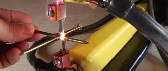
Do-it-yourself resistance welding from a welding transformer
Contact welding creates a welded connection between parts due to the following simultaneous effects on them:
- heating the area of their contact with an electric current passing through it;
- a compressive force is applied to the joint area.
There are three types of resistance welding:
- point;
- butt;
- suture
We will tell you about a homemade CT for the most popular: resistance spot welding (the other two require very complex equipment).
Spot resistance welding. East. https://moyasvarka.ru/process/kak-sdelat-kontaktnuyu-svarku-svoimi-rukami.html.
Explanations for the figure: 1 – electrodes supplying welding current to the products being welded; 2 – welded products with an overlap connection; 3 – welding transformer.
To carry out contact welding, depending on the thickness and thermal conductivity of the materials of the parts being welded, the following values of its main parameters are selected:
- electrical voltage in the power (welding circuit), V: 1…10;
- welding current value (welding pulse amplitude), A: ≥ 1000;
- heating time (passage of the welding current pulse), sec: 0.01…3.0;
In addition, the following must be provided:
- minor melting zone;
- significant compressive force applied to the welding site.
Scheme and calculation
Calculation of CT resistance welding is performed using the same algorithm as for arc welding (see above). When selecting data from a reference book (current strength and voltage of the secondary winding for spot welding of a selected grade of metal of a given thickness), it should be taken into account that the current strength of the secondary winding for such transformers is about 1000...5000 A. The secondary winding is designed, as a rule, for units of volts and It is just a few turns (sometimes one) of thick wire. Therefore, to adjust the welding current, the following diagram of the primary winding of the transformer is recommended.
Diagram of transformer windings for resistance welding. East. https://tutmet.ru/kontaktnaja-svarka-svoimi-rukami-shema-video.html.
Very often, during the operation of home-made products, it turns out that there is not enough power of the ST. In this case, it is possible to connect a second transformer in accordance with the proposed circuit.
Connection diagram of two spot welding transformers. East. https://tool-land.rusamodelnaya-tochechnaya-svarka.php.
Winding and installation
These operations are performed according to the same basic rules and in compliance with the requirements as for CT arc welding. The turns of the secondary winding should be secured with special care. To do this, you can use its leads by passing them through a heat-resistant insulator.
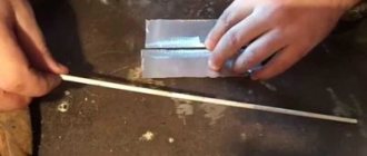
Copper rods are used as electrodes.
Electrode for spot welding in a clamp. East. https://tool-land.rusamodelnaya-tochechnaya-svarka.php.
It should be borne in mind that the larger the diameter of the electrode, the better. Under no circumstances should the diameter of the electrode be smaller than the diameter of the wire. For low-power STs, it is possible to use tips from powerful soldering irons. During operation, monitor the condition of consumables: the electrodes must be periodically sharpened - otherwise they will lose their shape. Over time, they wear down completely and require replacement.
Video
Here is an option for a spot welder from a microwave:
Recommendations for use
When performing welding work, it is necessary to comply with occupational safety requirements:
- the CT housing must be reliably grounded ;
- The welder must wear special clothing ;
- the head must be protected by a welder’s mask (Chameleon masks equipped with a self-darkening filter are very popular), etc.
When operating a resistance welding machine, the following additional requirements must be met :
- the welder needs to stand on a rubber mat;
- the worker must have rubber gloves on his hands;
- A welding helmet is not required, but safety glasses must be worn on the face.
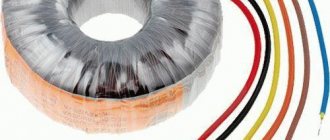
Manufacturing process
The efficiency of a transformer depends on the shape and size of the magnetic circuit. A toroidal core (donut-shaped) gives the best output characteristics, but a U- or W-shaped one is easier to manufacture, and a base for it is easier to find. Resistance welding devices usually have a U-shaped magnetic circuit. The technological process consists of calculating the required number of turns, making housings for the coils, winding the coils, installing the magnetic circuit and assembling everything into a single whole.
Types of magnetic cores of transformers