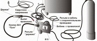
Differences from an inverter device
Such equipment differs from transformer equipment in the following characteristics:
- Light weight. If the mass of the transformer is about 35 kg, then for the inverter it does not exceed 15 kg. This makes it easy to move the device during operation.
- No transformer in the design. This eliminates energy consumption for heating the windings and magnetization reversal of the magnetic circuit. The efficiency increases. When using an electrode with a diameter of 3 mm, energy consumption does not exceed 4 kW. Under the same conditions, this parameter for the transformer is 7 kW.
- Possibility of obtaining current with any current-voltage indicators. Inverter-type devices are used for welding all metals. They work with stainless, alloy steel, copper, aluminum.
- Operating modes. The inverter does not require frequent interruptions for cooling.
- Possibility of fine tuning. The welder selects current and voltage values over a wide range. Using an inverter you can cook in different spatial positions. This produces the least amount of molten metal splashes.
Which welding source has the highest efficiency?
We continue to consider the types of welding machines. And we will consider the most modern of them - inverters, automatic and semi-automatic devices, as well as welding generators and machines for welding aluminum alloys. We will also consider what parameters you should pay attention to and how to choose a welder.
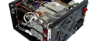
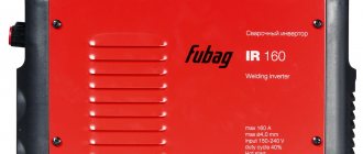
Inverter welder
These are the most modern welding machines, mass produced only since the 80s of the last century. They are current rectifiers with a built-in transistor .
In such devices, electrical energy changes its parameters several times. First of all, the current is rectified using semiconductors , then it is smoothed using a special filter.
Direct current is again converted into alternating current, but at a higher frequency, reaching several tens of kHz.
After this, the current passes through a small transformer , where the voltage decreases and its current increases. The rectifier and high-pass filter then begin to operate to create an electrical arc of direct current flowing to the electrodes.
The main feature of the welding inverter was the increase in current frequency. This made it possible to significantly reduce the weight and overall dimensions of the device.
Other advantages are:
- Long time of continuous operation.
- Increased efficiency (more than 80%), low losses and energy savings.
- Possibility of connecting to the household network of an apartment or house.
- Large current adjustment range, which allows the use of electrodes of different diameters, even very thin ones.
- Smooth voltage and current regulation.
- Formation of a high-quality weld.
- No metal spattering.
- Protecting the device from power surges.
- The operation of the device is controlled using microprocessors and control circuits, so the electric arc is quickly ignited and stabilized.
- Welding materials that cannot be welded with other machines.
- High electrical safety.
Flaws
- The device is highly sensitive to dust, which constantly enters the case due to the existing fan cooling. Metal dust can create a short circuit of elements in the housing, so the device requires periodic blowing with compressed air or cleaning it with a brush, especially in production or construction.
- High cost of the device compared to transformer devices. Repairing an inverter device will also be expensive. For example. If the power transistors fail, you will have to pay almost half the cost of the entire device.
- Possible interference in the household network, which negatively affects the operation of household devices.
- A complex device based on semiconductor power elements, highly sensitive to low temperatures, moisture, and condensation. In winter, some difficulties arise in work.
- Requires a warm heated room for storage.
An inverter welder will greatly simplify the work for a novice welder, and for a qualified specialist this device will allow the work to be completed quickly and with high quality.
Due to its small size and weight, the inverter device is very mobile, and for frequent movements around the site such a device is ideal. But all these advantages will require investing a lot of money.
Semi-automatic welding machines
The operation of a semi-automatic welding machine is that a special welding wire with a diameter of about 1 mm is fed into the welding zone by a special feeding mechanism, where it melts in a gaseous environment and enters the weld pool.
The air is displaced by gas near the weld pool, which protects the weld from oxygen. Typically, carbon dioxide, argon and other gases or mixtures thereof are used for these purposes.
If flux-cored wire is used for welding, then gas does not need to be supplied to the work area.
At its core, a semi-automatic welder is a stationary installation, which consists of a rectifier or inverter, a feed mechanism, a control system, a gas system and a torch with sleeves. The operating mode of the entire device is adjusted by using a certain type of filler wire, type of gas, adjusting the feed speed and current strength.
Advantages
- High quality seam of any length (from spot to long).
- Easy welding of thin-walled parts, especially during body work in a car service center.
- High speed.
- Lots of settings and adjustments.
- Large list of materials to be welded.
Welding generator
This is a rather complex device that includes a fuel-based electricity generator and a current source for welding. Moreover, this source can produce alternating and direct current.
This unit is an expensive product.
However, for construction sites or places where welding work is carried out, where there is no electricity or it is unstable, such a device will be the best choice.
Many may ask: are simple welding machines capable of operating from such a generator? Yes, they very well can. However, if household devices or other consumers are connected to the generator, then during welding work they will have to be disconnected from the generator, since the voltage will be unstable, which will lead to failure of the connected devices.
An important feature of this device is that to operate the welding machine you need a generator with a simple device, since welding does not require increased power source parameters. As a result, such a complex device has a lower cost than if you purchase a generator and welder separately.
If you have periodic power outages or no electricity at all, then it would be more profitable to purchase not a household welding machine, but a combined device - a welding generator.
In this case, the type of generator is first determined - diesel or gasoline.
Next, select the type of current source - rectifier, transformer or inverter, and then select the remaining parameters of the device that we considered earlier.
Aluminum alloy welding machine
A special feature of welding aluminum is its low melting point and usually the thickness of the metal. Therefore, traditional manual welding for steel is not suitable; extensive experience is required, which not all welders have. You need a welder who welds in a gas environment or an argon arc apparatus.
There are also multifunctional universal welding machines that are capable of welding several types of metals. The cost of such devices is very high, and they are practically not used for domestic needs. These are professional welders for widespread use.
They can operate in several modes:
- Argon arc welding.
- Manual welding with electrodes.
Both of these modes can occur in a gas shell environment using direct, alternating or pulsating current. Such devices have a lot of settings; they cook both steel and aluminum, even without additional processing, as well as titanium and stainless steel. In this case, the weld seam is of high quality.
Recommendations for selection
To make the right choice of welding machine, it is necessary to take into account certain parameters that should be considered in more detail.
Supply voltage
Welding machines can be three-phase or single-phase. For domestic use, you should choose single-phase devices or a universal welder.
Many welding machines are highly sensitive to voltage surges, and they may stop working or fail.
Therefore, inverter devices are usually equipped with special protection against power surges, which allows them to be used in networks where power parameters are unstable.
Household welding devices have a voltage range extension of up to 15%. Professional welding machines may have a higher voltage tolerance.
No load voltage
This is an important parameter that determines the welder’s ability to ignite an electric arc and maintain it during operation. To ignite an arc, a voltage is required that is twice the constant combustion voltage. Regulatory documents limit these parameters for alternating current - 80 V, for direct current - 90 V.
Based on practice, an arc can form at 30 V, since the devices of such devices often use various ingenious circuits to facilitate the occurrence of an arc.
Power
Manuals for welding machines usually indicate their maximum power. This corresponds to the highest peak loads on the electrical network.
Guided by this parameter, you need to choose the right place to connect the device so that cables and protection devices can ensure its normal operation.
Some manufacturers indicate the rated current of the circuit breaker in the passport.
If the welder can operate at reduced voltage, then its efficiency in extreme conditions will be significantly reduced. Therefore, it is necessary to have a power reserve of about 30%. If the welding machine is often used under extreme loads, its service life will be significantly reduced.
Welding transformer design
Such a device includes several components that create an electric arc capable of melting steel. The components change the parameters of the currents coming from the network.
The unit lowers the voltage, increasing the amperage.
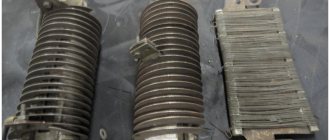
Welding of metals becomes possible thanks to the components included in the design of the device:
- magnetic circuit;
- primary winding of insulated cable;
- screw;
- moving secondary winding made of bare wire;
- running nut;
- handle that rotates the screw;
- clamps for fixing cables;
- cooling system.
We recommend reading Features of setting up the Chameleon welding helmet
The magnetic circuit does not affect the current parameters, it only forms a magnetic field. For this, a set of steel plates coated with an oxide composition is used. Some transformers include additional components that improve the performance of the equipment.
Instructions for safe use
The welding transformer is easy to use. Anyone with minimal knowledge of the welding process can operate it. The main condition for using the device is full compliance with safety regulations, ensuring the protection of eyes and hands with a mask and gloves. By fully complying with established standards, occupational diseases can be prevented, accidents can be eliminated, and the body can be protected from unexpected electrical failures.
The instructions for safe operation state that before working with the equipment, a person must properly, reliably ground the contacts, and then connect the equipment using an electrical panel with a separate connection to the RCD. In this case, the length of the wires should not exceed 10 m.
Note! When welding work is carried out outdoors, it is necessary to place the transformer under a canopy, in a covered pavilion. Be sure to turn off the equipment if there is heavy rain or snow. In addition, cables and wires must have proper insulation.
Welding work should be carried out away from others, in a special spacious and well-ventilated area. In damp conditions it is necessary to use rubber clothing and a mat. When working sitting or lying down, it is necessary to use a felt bedding.
Types and classification of devices
Welding units are classified according to the following characteristics:
- Size and weight. The devices can be compact, portable or stationary, moved using wheels or a hoist (suspended lifting device).
- Open circuit voltage of the welding transformer. In different models of devices, this parameter ranges from 48 to 70 V.
- Maximum current strength. For industrial models this parameter reaches 1000 A, for household models – 50-400 A.
- Voltage of current consumption, number of phases. There are single-phase or three-phase types.
- The nature of the presentation. The device can generate current continuously or pulsed.
- Diameter of connected electrodes.
Where to order and buy
You can order and buy a welding transformer at any site that specializes in professional construction equipment. When purchasing, you should consider the above criteria. Be sure to read reviews from real users, take into account the price and scope of application.
A welding transformer is a reliable, unpretentious device that can weld any metal thanks to a special current. It was created at the beginning of the last century to work in heavy and light industry. Later it became widespread for work in the construction industry. It has a durable design and works according to a certain principle that is understandable even to a layman.
The principle of working with characteristics
Devices for transformer welding function as follows:
- Current from the electrical network enters the primary winding. Here a magnetic flux appears, directed towards the core.
- The voltage is transmitted to the secondary winding.
- The ferromagnetic core generates a magnetic field. Electromotive forces of a variable nature are generated in 2 windings.
- The difference in the number of turns of the coils helps to change the current parameters to the volt-ampere indicators necessary for welding. Based on these values, the characteristics of the transformer unit are calculated.
The number of turns of the winding is directly related to the output voltage. A secondary coil wound in larger quantities increases the current strength. A transformer welding machine is a step-down device. The number of turns of the primary winding in it is greater than the secondary. You can regulate the output current by changing the gap between the coils.
Idling
The operating principle of the welding transformer includes 2 modes: idle and with load. During welding, the secondary coil creates a short circuit between the workpiece and the electrode. A powerful arc melts the material, forming a seam. After welding is completed, the secondary circuit is broken. The device starts to idle.
We recommend reading Current regulator for a welding machine
This mode of operation must be safe for the user. The maximum voltage value is 48 V. If the value exceeds the permissible values, the automatic limiter is activated. Grounding the unit body provides additional protection for the welder from electric shock.
Tools
0 votes
+
Vote for!
—
Vote against!
When searching for a suitable welding transformer, many abandon factory models in favor of homemade ones. The reasons for such a decision can be very diverse, ranging from unacceptable prices to the desire to make a welding transformer yourself. In fact, there are no particular difficulties in how to make a welding transformer; moreover, a homemade welding transformer can rightfully be considered a source of pride for any owner. But when creating it, it is impossible to do without knowledge about the structure and circuit of the transformer, its characteristics and calculations based on them.
- Performance characteristics of welding transformer
- Mains voltage and number of phases
- Rated welding current of the transformer
- Electrode diameter
- Welding current control limits
- Rated operating voltage
- Nominal operating mode
- Power consumption and output
- Open circuit voltage
- Welding transformer circuit
- Calculation of a welding transformer
Performance characteristics of welding transformer
Any power tool has certain performance characteristics and a welding transformer is no exception. But in addition to the usual ones, such as power, number of phases and the network voltage required for operation, the welding transformer has a whole set of unique characteristics, each of which will allow you to accurately select a device in the store for a specific type of work. For those who are going to make a welding transformer with their own hands, knowledge of these characteristics will be required to perform calculations.
But before moving on to a detailed description of each characteristic, it is necessary to understand what the basic operating principle of a welding transformer is. It is quite simple and consists of converting the incoming voltage, namely lowering it. The decreasing current-voltage characteristic of a welding transformer has the following dependence - when the voltage (Volt) decreases, the welding current (Ampere) increases, which allows the metal to melt and weld. The entire operation of the welding transformer, as well as other associated performance characteristics, is based on this principle.
Mains voltage and number of phases
With this characteristic everything is quite simple. It indicates the voltage required for operation of the welding transformer. This can be 220 V or 380 V. In practice, the network voltage may fluctuate slightly within +/- 10 V, which may affect the stable operation of the transformer. When calculating for a welding transformer, the mains voltage is a fundamental characteristic for the calculations. In addition, the number of phases depends on the network voltage. For 220 V there are two phases, for 380 V there are three. This is not taken into account in the calculations, but this is an important point for connecting the welding machine and its operation. There is also a separate category of transformers that can operate on both 220 V and 380 V.
Rated welding current of the transformer
This is the main operating characteristic of any welding transformer. The ability to cut and weld metal depends on the strength of the welding current. In all welding transformers, this value is indicated as the maximum, since this is exactly how much the transformer is capable of delivering at the limit of its capabilities. Of course, the rated welding current can be adjusted to allow work with electrodes of different diameters, and for this purpose a special regulator is provided in the transformers. It should be noted that for household welding transformers created by yourself, the welding current does not exceed 160 - 200 A. This is primarily due to the weight of the transformer itself. After all, the greater the strength of the welding current, the more turns of copper wire are required, and these are extra, unbearable kilograms. In addition to the welding transformer, the price depends on the metal for the wires of the windings, and the more wires were used, the more expensive the device itself will cost.
Electrode diameter
When working with a welding transformer, weldable electrodes of various diameters are used to weld metal. The ability to use an electrode of a certain diameter depends on two factors. The first is the rated welding current of the transformer. The second is the thickness of the metal. The table below shows the diameters of the electrodes depending on the thickness of the metal and the welding current of the transformer itself.
As can be seen from this table, using a 2 mm electrode will be simply pointless at a current of 200 A. Or vice versa, a 4 mm electrode is useless at a current of 100 A. But quite often it is necessary to weld metal of different thicknesses with the same machine and for Therefore, welding transformers are equipped with current regulators.
Welding current control limits
To weld metal of different thicknesses, electrodes of different diameters are used. But if the welding current is too high, the metal will burn out during welding, and if it is too low, it will not be possible to melt it. Therefore, in welding transformers for these purposes, a special regulator is built in, which allows you to reduce the rated welding current to a certain value. Typically, in home-made welding transformers, several stages of adjustment are created, ranging from 50 A to 200 A.
Rated operating voltage
As already noted, the welding transformer converts the incoming voltage to a lower value of 30 - 60 V. This is the rated operating voltage, which is necessary to maintain a stable arc. The possibility of welding metal of a certain thickness also depends on this parameter. Thus, welding thin sheet metal requires low voltage, and thicker metal requires high voltage. When calculating, this indicator is very important.
Nominal operating mode
One of the key performance characteristics of a welding transformer is its rated operating mode. It indicates a period of continuous operation. This figure for factory welding transformers is usually about 40%, but for homemade ones it can be no higher than 20 - 30%. This means that out of 10 minutes of work, you can continuously cook for 3 minutes, and let rest for 7 minutes.
Power consumption and output
Like any other power tool, a welding transformer consumes electricity. When calculating and creating a transformer, the power consumption indicator plays an important role. As for the output power, it should also be taken into account, since the efficiency of the welding transformer directly depends on the difference between these two indicators. And the smaller this difference, the better.
Open circuit voltage
One of the important operating characteristics is the open circuit voltage of the welding transformer. This characteristic is responsible for the ease of appearance of the welding arc, and the higher the voltage, the easier the arc will appear. But there is one important point. To ensure the safety of the person working with the device, the voltage is limited to 80 V.
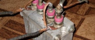
Welding transformer circuit
As already noted, the operating principle of a welding transformer is to lower the voltage and increase the current. In most cases, the design of a welding transformer is quite simple. It consists of a metal core, two windings - primary and secondary. The photo below shows the design of a welding transformer.
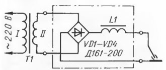
With the development of electrical engineering, the basic design of a welding transformer has been improved, and today welding machines are produced that use chokes, a diode bridge, and current regulators in their circuitry. The presented diagram shows how the diode bridge is integrated into the welding transformer (photo below).
One of the most popular homemade welding transformers is the toroidal core transformer, due to its light weight and excellent performance characteristics. The diagram of such a transformer is presented below.
Today there are many different welding transformer circuits, ranging from classic ones to inverter and rectifier circuits. But to create a welding transformer with your own hands, it is better to choose a simpler and more reliable circuit that does not require the use of expensive electronics. Such as, for example, a welding toroidal transformer or a transformer with a choke and diode bridge. In any case, to create a welding transformer, in addition to the circuit, you will have to perform certain calculations in order to obtain the required performance characteristics.
Calculation of a welding transformer
When creating a welding transformer for specific purposes, it is necessary to determine its operating characteristics in advance. In addition, the calculation of the welding transformer is performed to determine the number of turns of the primary and secondary windings, the cross-sectional area of the core and its window, transformer power, arc voltage, and other things.
To perform the calculations you will need the following initial data :
- input voltage of the primary winding (V) U1;
- rated voltage of the secondary winding (V) U2;
- rated current of the secondary winding (A) I;
- core area (cm2) Sc;
- window area (cm2)So;
- current density in the winding (A/mm2).
Let's consider the example of calculation for a toroidal transformer with the following parameters: input voltage U1=220 V, rated voltage of the secondary winding U2=70 V, rated current of the secondary winding 200 A, core area Sc=45 cm2, window area So=80 cm2, density current in the winding is 3 A/mm2.
First, we calculate the power of the toroidal transformer using the formula:
P overall = 1.9*Sc*So . As a result, we get 6840 W or simplified 6.8 kW.
Important! This formula is applicable only for toroidal transformers. For transformers with a core type PL, ShL, a coefficient of 1.7 is used. For transformers with core type P, Ш – 1.5.
The next step is to calculate the number of turns for the primary and secondary windings. To do this, you will first have to calculate the required number of turns per 1 V. To do this, we use the following formula: K = 35/S . As a result, we get 0.77 turns per 1 V of consumed voltage.
Important! As in the first formula, factor 35 is applicable only for toroidal transformers. For transformers with a core type PL, ShL, a coefficient of 40 is used. For transformers with a core type P, Sh – 50.
Next, we calculate the maximum current of the primary winding using the formula: Imax = P/U . As a result, we obtain a current for the primary winding of 6480/220 = 31 A. For the secondary winding, we take the current strength as a constant of 200 A, since it may be necessary to weld metal of various thicknesses with electrodes with a diameter of 2 to 3 mm. Of course, in practice, 200 A is the maximum current strength, but a reserve of a couple of tens of amperes will allow the device to operate more reliably.
Now, based on the data obtained, we calculate the number of turns for the primary and secondary windings in a transformer with step regulation in the primary winding. The calculation for the secondary winding is carried out using the following formula W2 = U2 * K , as a result we get 54 turns. Next we move on to calculating the stages of the primary winding. To do this, we use the formula W1st = (220*W2)/Ust .
Where:
Ust is the required output voltage of the secondary winding.
W2 – number of turns of the secondary winding.
W1st – number of turns of the primary winding of a certain stage.
But before you start calculating the turns of the primary winding stages, you need to determine the voltage for each. This can be done using the formula U=P/I , where:
P – power (W).
U – voltage (V).
I – current (A).
For example, we need to make four stages with the following rated current on the secondary winding: 160 A, 130 A, 100 A and 90 A. Such a spread will be needed to use electrodes of different diameters and weld metal of different thicknesses. As a result, we get Ust = 40.5 V for the first stage, 50 V for the second stage, 65 V for the third stage and 72 V for the fourth. Substituting the obtained data into the formula W1st = (220*W2)/Ust , we calculate the number of turns for each stage. W1st1 = 293 turns, W1st2 = 238 turns, W1st3 = 182 turns, W1st4 = 165 turns. During the process of winding the wire, a tap for the regulator is made on each of these turns.
It remains to calculate the wire cross-section for the primary and secondary windings. To do this, we use the current density indicator in the wire, which is equal to 3 A/mm2. The formula is quite simple - you need to divide the maximum current of each winding by the current density in the wiring. As a result, we obtain for the primary winding a wire cross-section Sprim = 10 mm2. For the secondary winding, the wire cross-section Ssecond = 66 mm2.
When creating a welding transformer with your own hands, you need to perform all of the above calculations. This will help you select all the necessary parts correctly and then assemble the device from them. For a beginner, performing calculations may seem like a very confusing task, but if you understand the essence of the actions being performed, everything will not be so difficult.
Modification schemes
Changes are often made to the design of a standard device to help improve performance.
With shunt
The dissipation of the magnetic field is facilitated by a change in the spatial position of the components of the magnetic circuit.
When steel elements are displaced, the resistance of the flow through the air increases.
When the shunt is fully inserted, the parameter begins to depend on the distance between the part and the components of the magnetic circuit. Devices with this principle of operation are intended for use in industrial environments.
With winding in sections
This welding machine design is considered obsolete. Previously, this equipment was used in domestic and industrial settings. There are several options for choosing the number of turns in the primary and secondary windings.
Thyristor devices
To change the voltage and current, a phase shift of thyristors is used. When assembling a single-phase device, 2 parts are used, installed opposite each other. Thyristors are adjusted symmetrically and synchronously.
In semiconductor transformers, these elements are placed on the primary winding, which is explained by the following reasons:
- The strength of the secondary current in such devices is higher than in thyristors.
- When installing the latter on the primary coil, the efficiency increases. This is due to the reduction in voltage losses.
Transformer no-load mode
One of the most used electrical devices is the transformer. This equipment is used to change the magnitude of electrical voltage. Let's consider the features of the transformer no-load mode, taking into account the rules for determining characteristics for various types of devices.
The transformer consists of primary and secondary windings located on the core. When voltage is applied to the input coil, a magnetic field is formed, inducing a current in the output winding. The difference in characteristics is achieved due to the different number of turns in the input and output coils.
Transformer operating principle
What is idle mode
The idle mode is understood as the state of the device in which, when an alternating current is supplied to the input coil, the output coil is in an open state. This situation is typical for a unit connected to the mains, provided that the load to the output circuit has not yet been turned on.
Short circuit mode
How is the idle test performed?
When conducting an idle test, it becomes possible to determine the following characteristics of the unit:
- transformation ratio;
- power loss in steel;
- parameters of the magnetizing branch in the equivalent circuit.
For the experiment, a rated load is applied to the device.
When conducting an idle test and calculating characteristics based on this technique, it is necessary to take into account the type of device.
In this state, the transformer has zero useful power due to the absence of electric current at the output coil.
The applied load is converted into heat loss on the input coil I02×r1 and magnetic core loss Pm. Due to the insignificance of heat losses at the input, they are not taken into account in most cases.
Therefore, the total value of no-load losses is determined by the magnetic component.
Also read: What is pitch voltage
The following are the features of calculating characteristics for various types of transformers.
For single phase transformer
The no-load test for a single-phase transformer is carried out with the connection:
- voltmeters on the primary and secondary coils;
- wattmeter on the primary winding;
- ammeter at the input.
The devices are connected according to the following scheme:
To determine the no-load current Iо, use an ammeter reading. It is compared with the rated current value using the following formula, resulting in a percentage:
Iо% = I0×100/I10.
To determine the transformation ratio k, determine the value of the rated voltage U1н according to the readings of the voltmeter V1 connected to the input. Then, using the voltmeter V2 at the output, the value of the rated voltage U2O is taken.
The coefficient is calculated using the formula:
K = w1/w2 = U1н/ U2О.
The amount of loss is the sum of the electrical and magnetic components:
P0 = I02×r1 + I02×r0.
But, if we neglect electrical losses, the first part of the sum can be excluded from the formula. However, an insignificant amount of electrical losses is typical only for low-power equipment. Therefore, when calculating the characteristics of powerful units, this part of the formula should be taken into account.
No-load losses for transformers with a power of 30-2500 kVA
For three-phase transformer
Three-phase units are tested according to a similar scheme. But the voltage is supplied separately for each phase, with the appropriate installation of voltmeters. You will need 6 units of them. You can conduct an experiment with one device, connecting it to the required points one by one.
When the rated voltage of the winding electric current is more than 6 kV, 380 V is supplied for testing. The high-voltage mode for conducting the experiment will not allow achieving the necessary accuracy for determining the indicators. In addition to accuracy, the low-voltage mode ensures safety.
The following scheme applies:
The operation of the device in idle mode is determined by its magnetic system. If we are talking about a type of device similar to a single-phase transformer or an armored rod system, the closure of the third harmonic component for each phase will occur separately, with a value increasing to 20 percent of the active magnetic flux.
Also read: Purpose of voltage indicators
As a result, an additional EMF arises with a fairly high rate - up to 60 percent of the main one. There is a danger of damage to the insulating layer of the coating with the possibility of failure of the device.
It is preferable to use a three-rod system, when one of the components will not pass through the core, with a circuit through air or another medium (for example, oil), with low magnetic permeability. In such a situation, the development of a large additional EMF, leading to serious distortions, will not occur.
For welding transformer
For welding transformers, idling is one of the modes of their constant use in operation. During welding in operating mode, the second winding is short-circuited between the electrode and the metal of the part. As a result, the edges melt and a permanent connection is formed.
After finishing work, the electrical circuit is broken and the unit goes into idle mode. If the secondary circuit is open, the voltage in it corresponds to the EMF value. This component of the power flow is separated from the main one and is closed through the air.
To avoid danger to humans when the machine is idling, the voltage value should not exceed 46 V. Considering that in some models the value of these characteristics exceeds the specified value, reaching 70 V, the welding unit is equipped with a built-in performance limiter for idle mode.
The blocking is activated within a time not exceeding 1 second from the moment the operating mode is interrupted. An additional protective measure is a grounding device for the welding unit housing.
Measures to reduce no-load current
The current when the transformer is in idle mode occurs due to the design features of the core. A ferromagnetic material exposed to an alternating current electric field is characterized by the induction of eddy inductive Foucault currents, which cause heating of the element.
To reduce eddy currents, the core is not made as a single piece, but is assembled from a package of thin plates. The plates are insulated from each other. An additional measure is to change the properties of the material itself, which makes it possible to increase the threshold of magnetic saturation.
Also read: Switching without excitation - transformer off-circuit switching
To prevent a break in the magnetic flux with the appearance of a stray field, the plates are carefully adjusted during the recruitment process. Individual elements are ground to obtain a smooth, perfectly fitting surface.
Losses are also reduced due to more complete filling of the magnetic circuit window. This allows us to ensure optimal weight and dimensions of the unit.
Idling of a transformer is a mode in which important characteristics can be calculated. This is carried out for equipment in operation and at the design stage.
Advantages and disadvantages
The positive qualities of transformer equipment include:
- High efficiency, ease of operation and maintenance. Repairing the device does not involve large expenses, which allows it to be used at home.
- Low cost.
The disadvantages include:
- Arc instability. This is due to the AC parameters. To work with such devices, specialized electrodes are used.
- Changes in output voltage, which negatively affect the quality of the weld.
- Inability to use for joining parts made of non-ferrous metals or stainless steel.
- Dimensions and heavy weight, causing difficulties when moving.
We recommend reading: Do-it-yourself reliable plasma cutter. Instructions
The role of the transformer in welding
AC welding transformers are used in manual arc welding using stick electrodes, in mechanized welding using flux, and in argon arc welding for joining parts made of aluminum alloys.
The purpose of the welding transformer is to generate the voltage required for welding, certain constant external characteristics and to regulate the welding current.
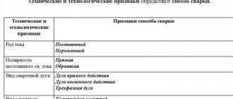
The requirements for external parameters are determined based on the following indicators:
- type of electrode - it can be a melting or non-melting rod;
- the nature of the working environment - open arc, submerged arc, in protective gas;
- degree of automation of the welding process - manual, automatic, semi-automatic;
- The method of regulating the combustion mechanism is self-regulation, automatic.
Manual arc welding with coated rods, argon arc welding with a non-consumable tungsten electrode, mechanized submerged arc welding on automatic machines with control of the filler wire feed speed depending on the arc voltage - methods of joining metal parts in which a falling current-voltage characteristic is used.
Types of welding transformers.
A falling current-voltage characteristic implies operation of the device in welding current regulator mode. Based on technological and economic considerations, smooth step control is used.
This type of control involves two or more stages of regulation, combined with a smooth change in the current value in each stage.
The rigid current-voltage characteristic is used in automatic submerged arc welding at a constant filler wire feed speed, regardless of arc voltage.
The power supply in this case works as a voltage regulator.
The voltage change can be:
- smooth;
- stepped;
- mixed.
The amount of welding current depends on the speed at which the electrode wire is fed. The power source, in turn, sets the arc voltage and ensures self-regulation of its length.
Depending on the number of phases there are:
- Single-phase welding transformer - a model that operates only at a voltage of 220 V. Designed for domestic needs.
- Three-phase transformer - operates at a network voltage of 380 V. Such models are capable of providing high current output, which makes it possible to connect metal parts of large thickness.
Features of choosing a welding transformer
When deciding which device to buy, take into account the following criteria:
- Types of metals to be welded, parameters of future seams. To work with steel, manual equipment with direct or alternating current is sufficient. The operational qualities of the transformer allow you to weld products from any ferrous metals.
- Current strength. In domestic conditions, a unit producing 200 A is sufficient.
- Operating principle. Semi-automatic devices are reliable and easy to use, but they are expensive. When using manual units, the welder will have to independently control all parameters.
- Reliability of the manufacturer.
Main criteria for selection
In order for the device to have high reliability, good maintainability and a durable design, when choosing, it is necessary to pay attention to the current regulation range, on-time, voltage, phase, power consumption, type of cooling and number of posts. It is also important to look at reviews regarding the lack of large dimensions, weight, low arc stability, low PV, strong dependence of seam quality on skill, high energy consumption and the inability to use the device to weld non-ferrous metals and alloys with each other.
You might be interested in cable wiring diagrams
Power is the main criterion when choosing
Note! You need to choose a device taking into account the current strength. Household units operate at 200 A, semi-professional - up to 300 A, and professional - over 300 A. When choosing, you should look at the thickness of the electrodes. The optimal diameter is 2-5 mm for home work.
What malfunctions can there be
When working with a welding transformer, the following problems often arise:
- No arcing, cooling fan failure to start. The main reason is a violation of the integrity of the power cable. It is less common to detect damage to other equipment components or activation of overheating protection.
- No welding arc when the fan is running. It is observed when there is a breakdown in communication between the internal components of the system.
- No electric arc when the warning light is on. This problem occurs when the protective mode is triggered.
- Formation of a large amount of splashes. The seam quality remains low. It is worth checking that the wires are connected correctly and changing the polarity.
Advantages and disadvantages of a transformer over an inverter
When comparing a transformer-type welding machine with an inverter, the advantages include:
- the price is 2 - 3 times less;
- the design is simpler, since there are no electronic components;
- repairs are cheaper;
- easy to assemble with your own hands.
Flaws:
- weight and dimensions, with equal characteristics, are greater;
- higher power consumption when working with the same electrodes;
- arc instability due to mains voltage fluctuations;
- lack of additional functions that even budget inverters have.
Despite the shortcomings of transformers, we must not forget that the quality of the seams does not depend on the complexity of the apparatus, but on the skill of the welder.
How to mount the device yourself
The main part of a homemade unit is the core. It is made of transformer steel, which is quite difficult to buy. The resulting structure has the shape of a rectangle with a cross-section of more than 55 cm². When forming the primary and secondary coils, install the adjusting screw. It is used to move the movable winding.
The wire cross-section of the first coil must be more than 5 mm². To assemble the transformer, cables with heat-resistant insulation are used.
The secondary winding is formed from a copper conductor with a cross section of 30 mm². At the last stage, a textolite body is assembled, which serves to protect the welder from electric shock.