How does an angle grinder work?
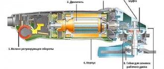
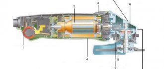
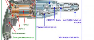
The design of the grinder consists of the following main parts: electrical and mechanical . In the mechanical component of the angle grinder, the main character is a bevel gearbox , which reduces the speed to an acceptable value. In an electric the commutator motor determines the operation of the angle grinder, where power is transferred to it using a special switch. Of course, its failure interrupts the supply of electrical energy from the network.
Scheme of operation of the grinder. Source here
The start button is broken, reasons
The grinder switch is an entire starting device , in which the button itself is only the point of application of force to change the operating modes of the power tool. Transmission to the contact device is carried out using a mechanical lever system , where even structural elements of the housing take part in the fixation.
The switch is located on the side of the body of the angle grinder Interskol
The contact device includes a capacitor as an element that reduces the possibility of sparks in the brush-collector assembly. Some angle grinders are equipped with a soft start circuit and a speed controller located in the same circuit with the start button. The main reasons for the failure of the starting device are as follows.
- Mechanical wear of the contacting surfaces of the button, lever, and body of the angle grinder. These structural elements can also fail due to loss of integrity (breakage).
- The elements included in the contact device may fail due to melting due to the current exceeding the rated value.
- Failure of the electronic soft start circuit.
The listed reasons are most often found when the starting device breaks down.
Where is the spindle lock button located on the angle grinder and how necessary is it?
The latch is a spring-loaded metal rod, on one end of which the button body is placed, and the other can fit into one of the holes in the body of the gearbox bevel gear. From the description it follows that the button should be located on the gearbox housing, not far from the spindle shaft.
Locking button on the body of the Interskol angle grinder. Photo VseInstruments.ru
By pressing the button and rotating the shaft, the locking rod gets into one of the holes on the gear. Holding the button in this position with one hand, unscrew/tighten the flat threaded washer that clamps the working tool with the other hand. The stationary spindle makes this operation possible.
The power button does not lock
Frequently pressing the button with force leads to wear on the contacting surfaces, and the button no longer locks. This defect is one of the most common that occurs during the operation of grinders.
In the following video, the Makita model grinder does not have the button locked in the required position . After disassembly, the worn surfaces on the button and the fixing groove on the body of the angle grinder are clearly visible. Repairs are made in two ways.
Replacing the worn button with a new one
Here you should remove the radius of curvature on the fixing groove and align the landing plane under the button. In this case, the processing is carried out very carefully with minimal removal of plastic material. The properties of plastic, as a fragile soft material, make it possible to select a machining mode with low tool speeds, which allows you to regulate its optimal feed when eliminating surface defects.
With worn button fix
The author is right that it is not always possible to find a new button to replace a worn one. The button restoration method is relevant, especially for craftsmen working outside the scope of specialized retail outlets. Important: clean the seating surface of the button with a file no more than a few tenths of a millimeter, and just level the contact surface of the “tendril” of the button without removing excess material.
These methods are one-time in nature; the next such breakdown may lead to the replacement of parts with new ones.
Is it possible to do without it?
The locking button is a convenient attribute of the grinder for removing and replacing the working tool. It will serve faithfully for a long time if you follow some recommendations.
Insert the working tool correctly. For example, the cutting wheel should be placed on the side facing the pressure washer that is made of the working material of the wheel. The side with the metal ring of the circle should be adjacent to the base surface of the angle grinder. A metal clamping nut will not have a strong grip on the material from which the circle is made; with a metal ring, the grip is much stronger (more theory on proper installation of discs is below in the video).
Jamming will be greatly reduced by using paper or cardboard spacers under the pressure washer. Usually cardboard ones are supplied complete with an angle grinder. When destroying stocks, there is the option of using thin nylon gaskets. In case of jamming, in order to maintain the integrity of the locking button, it can be easily melted using a blowtorch and the pressure washer can be easily unscrewed.
If an accident does occur and the locking button on the angle grinder breaks, there are ways to remove the work tool without it.
On the working shaft of the angle grinder behind the base washer there are ground shaft surfaces for fixing the washer. Access to them is limited due to the narrow gap. If you grind down the jaws of a wrench (size 17 is usually suitable), you can get to the flat surfaces of the shaft and prevent it from turning. In some cases, it is recommended to remove the shaft and increase the width of the key planes so as not to damage the key by grinding off the jaws.
- You can use a vice in a locksmith shop. To do this, the worn or broken circle is broken off flush to the surfaces of the clamping washers. This gives access to the gearbox cover bolts. They are easily unscrewed, the gear is removed from the gearbox and clamped in a vice with soft jaws. In this position, the clamping washer can be unscrewed with standard plumbing tools.
- Use a thin steel sheet (the thickness should be slightly less than that of the working tool). Remains of working tools are removed to the maximum extent possible. The sheet is clamped in the device and the remaining material is removed against its edge using a switched-on grinder. Thus, the load on the clamping nut is relieved and it can be unscrewed freely.
- The clamping washer can be heated, for example, with a gas torch or blowtorch. When heated, it becomes more pliable during the unscrewing process. However, strong heating of the entire mechanism negatively affects the lubrication of the gears of the gearbox - it becomes very liquefied and loses its properties.
- The method of unscrewing the nut by hitting it with a sharp object or with a hammer drill set to chiseling mode into the hole for the key pin looks less aesthetically pleasing, but allows you to achieve the desired result.
There are quite a lot of other methods that are not listed here, because grinders are used by craftsmen whose creativity knows no bounds.
The button does not hold, the tool turns off
In the following video, while the grinder is working with the same Makita model as in the previous video, the button is triggered by increased vibration and the grinder turns off . The correction method used is extremely simple; even the grinder does not need to be disassembled. A sharp utility knife is sufficient.
The idea is that during operation, plastic growths form on the latch groove due to friction against the “tendril” of the button, which prevent it from being pressed tightly against the surface of the latch groove. By carefully cutting them off with a utility knife, you bring the grinder to the desired state, and it no longer turns off during operation. Here it is important to remove the build-up; the slightest careless movement will lead to a damaged seating surface and additional costs for repairing the switch.
Where can I buy
Employees of companies that sell power tools and components for them offer buttons for angle grinders of various types and brands.
So, there is a situation: yesterday, out of the blue, the button on the grinder fell out (ZUBR machine, 1100W, 125 disc). It seems that the device is under warranty (not even a year old) - but I don’t need to wander around to service centers, but to work... so I disassembled it myself... As a result, what we have is a broken plastic thing, which is located in the body of the instrument and to which the main one is attached power button (it’s plastic, shaped like an “G”). This is not available anywhere in the city - not even in the service center... What should I do, what can I replace it with? Or what should we do now?
Mechanical malfunctions of angle grinders
An angle grinder is an angle grinder designed to perform cutting, grinding, and polishing work. The grinder is subjected to heavy loads during operation and works in a dusty environment.
Excessive loads when using an angle grinder in the “Cutting” mode cause increased wear not only of the bearing, but also of the gear teeth of the gearbox.
The main mechanical malfunction of the angle grinder is wear or destruction of the sliding bearing on the shaft of the large helical gear of the gearbox.
It is not difficult to troubleshoot an angle grinder if you have its diagram, description and recommendations for performing repair work at hand.
Repair of plain bearings
The weak point of any angle grinder is the bearings. And although there are few of them in the design, only three, they are the ones that most often lead to mechanical failures. Bearings are negatively affected by:
- high rotation speed;
- work at extreme conditions;
- insufficient amount of lubricant;
- ingress of dust or dirt;
- untimely replacement or destruction of carbon brushes.
The design of any angle grinder allows for quick and easy replacement of any bearing.
Malfunctions of the angle grinder associated with wear or destruction of the sliding bearing on the gearbox shaft are characterized by the appearance of an unpleasant extraneous sound.
Destruction of the sliding bearing is detected by checking the play of the working tool installation shaft. Determined by rocking the shaft in different directions when installing the working tool.
When installing the working tool again, check the shaft play by rocking its end in different directions. There should be no or minimal play.
The appearance of play indicates the need to replace the plain bearing.
Bearing repair involves removing it from the housing and removing it from the gearbox shaft.
It is better to remove the bearing from the shaft using a puller. It is best to remove the inner race of a damaged bearing using a tap of the required diameter, previously screwed into the race.
The bearings are removed from the rotor using a puller or the traditional method.
Keys or strips of metal are inserted into the vice, the bearings are placed on the keys and, using a soft metal attachment and a hammer weighing at least 400 g, are knocked out from the shaft axis.
Grinder gearbox repair
The degree of wear of the grinder gears is checked for the contact patch. The gearbox is first completely cleaned of old grease. A special blue is applied to the small gear of the gearbox, and the gearbox rotates. Next you need to remove the driven large helical gear and look through a magnifying glass at the contact patch. It should occupy a total of at least 50% of the tooth surface.
Otherwise, the gears must be replaced or the tooth profile adjusted. Correcting the tooth profile has been described more than once on the pages of this site.
But such a malfunction can only be eliminated by an experienced technician. Most often, licked, cut or destroyed gears are replaced entirely, and in pairs.
Is it possible to do without it?
The latch is located in the front part of the body of the Hammer USM 850A angle grinder. Photo 220Volt
The locking button is a convenient attribute of the grinder for removing and replacing the working tool. It will serve faithfully for a long time if you follow some recommendations.
Jamming will be greatly reduced by using paper or cardboard spacers under the pressure washer. Usually cardboard ones are supplied complete with an angle grinder. When destroying stocks, there is the option of using thin nylon gaskets. In case of jamming, in order to maintain the integrity of the locking button, it can be easily melted using a blowtorch and the pressure washer can be easily unscrewed.
If an accident does occur and the locking button on the angle grinder breaks, there are ways to remove the work tool without it.
On the working shaft of the angle grinder behind the base washer there are ground shaft surfaces for fixing the washer. Access to them is limited due to the narrow gap. If you grind down the jaws of a wrench (size 17 is usually suitable), you can get to the flat surfaces of the shaft and prevent it from turning. In some cases, it is recommended to remove the shaft and increase the width of the key planes so as not to damage the key by grinding off the jaws.
Grinder Metabo W 750-125 with black stop button. Photo 220Volt
- You can use a vice in a locksmith shop. To do this, the worn or broken circle is broken off flush to the surfaces of the clamping washers. This gives access to the gearbox cover bolts. They are easily unscrewed, the gear is removed from the gearbox and clamped in a vice with soft jaws. In this position, the clamping washer can be unscrewed with standard plumbing tools.
- Use a thin steel sheet (the thickness should be slightly less than that of the working tool). Remains of working tools are removed to the maximum extent possible. The sheet is clamped in the device and the remaining material is removed against its edge using a switched-on grinder. Thus, the load on the clamping nut is relieved and it can be unscrewed freely.
- The clamping washer can be heated, for example, with a gas torch or blowtorch. When heated, it becomes more pliable during the unscrewing process. However, strong heating of the entire mechanism negatively affects the lubrication of the gears of the gearbox - it becomes very liquefied and loses its properties.
- The method of unscrewing the nut by hitting it with a sharp object or with a hammer drill set to chiseling mode into the hole for the key pin looks less aesthetically pleasing, but allows you to achieve the desired result.
There are quite a lot of other methods that are not listed here, because grinders are used by craftsmen whose creativity knows no bounds.
How to properly disassemble an angle grinder gearbox
When repairing the gearbox of any angle grinder, the most difficult task is removing the gears and pressing out the support bearing.
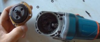
Disassembling the gearbox begins with removing the gearbox cover pos. 1 and disconnecting the stator housing and freeing the rotor pos. 2. The freed rotor is clamped in a vice and the fastening nut pos. 3 of the drive small gear is unscrewed.
The spindle bearing is pressed into the gearbox cover. To remove the bearing, in some angle grinders you must remove the retaining ring that secures the support bearing and remove the bearing.
The destroyed bearing, pos. 1, in the gearbox housing, pos. 2, is easiest to get out by prying it off with a screwdriver.
In other models, a locking ring secures the gear in the spindle.
The driven large gear is mounted on the spindle in several ways:
- The gear is pressed onto the spindle.
- The gear is secured with a key.
The driving small gear is either screwed onto the shaft along the left-hand thread (in some Sparky models, the thread is right-handed), or is fixed with a key connection and clamped with a nut.
How to remove gears
Grinders up to 1000 W use spur gears, while angle grinders use helical gears.
Electrical malfunctions of the angle grinder
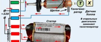
The electrical circuit of the main part of the grinders is almost the same. The rotor transmits torque through a gearbox to the working tool. The rotor rotates in the stator field. The control circuits consist of a button that regulates speed and smoothly starts the tool, and carbon brushes that transmit alternating voltage to the commutator lamellas. Power is supplied to the instrument via the connecting cable.
The main electrical malfunctions of an angle grinder include:
- break of the power cable at the entrance to the instrument;
- destruction or wear of carbon brushes;
- failure of the power button;
- stator break or short circuit;
- rotor break or short circuit;
- peeling or deterioration of collector lamellas.
Electrical malfunctions of an angle grinder are best determined with a tester or other device. A homemade device, popularly called an “arkashka” .
The grinder scheme is quite simple and does not require special knowledge. You just need to be careful and safe when performing repair work and have a high school level knowledge of electrical engineering.
Finding a broken power wire
One of the most common breakdowns of an angle grinder is the inability to turn on the tool or spontaneous stopping during operation. The cause of malfunctions of this kind is a break in the power cable, pos. 27, at the entry point. The malfunction is eliminated by replacing the cable or discarding the failed section. The fault can be easily found using a tester.
If you don’t have a tester at hand, but have a screwdriver with a neon indicator light, then the fault can be found by connecting the power wires to the phase one by one.
Carbon brush malfunctions
The reliable operation of any power tool depends to a large extent on the integrity and proper operation of the carbon brushes. The high-quality fit of the carbon brushes and their correct location relative to the commutator lamellas affect the performance of the rotor commutator.
Remember! The length of the carbon electric brush cannot be less than 8 mm.
Timely replacement of carbon brushes allows you to avoid most malfunctions.
The degree of wear of carbon brushes is characterized by the types of sparking at the commutator site. The sparking should be uniform across the entire contact patch of the carbon brush and lamellas and not exceed a length of more than 8 mm. Circular sparking indicates a malfunction in the rotor circuits.
In grinders, it is recommended to use carbon brushes only from tool manufacturers. Homemade carbon brushes can be installed, but only for a short period and immediately replaced as soon as possible.
Repair of the power button and speed controller
Malfunctions of the power button most often manifest themselves in difficult and unreliable turning on of the tool when starting. This malfunction appears and disappears spontaneously.
It is unacceptable to operate an angle grinder with a faulty power button. This malfunction leads to cutting discs jamming during operation and their destruction with unpredictable consequences.
The malfunction is eliminated by completely replacing the button with a new one.
Modern models of angle grinders have a built-in soft start device with a speed controller. It cannot be repaired and will require complete replacement. No, advanced left-handed craftsmen, of course, will be able to repair such a unit.
Stator repair
The failure of the stator is indicated by spontaneous spinning of the machine shaft; the angle grinder begins to gain maximum speed. Such a malfunction indicates the appearance of an interturn short circuit in the stator winding.
Some faults can only be fixed by specialists. Extending the uninterrupted operation of the stator can only be done by timely cleaning, lubrication and replacement of carbon brushes and bearings.
Typically, the stator fails quite rarely. This is caused by frequent overheating of the tool during operation. The malfunction is manifested by strong heating of the grinder body and the appearance of a smell of burnt insulation.
There can be either an open circuit or a short circuit in the stator. Without disassembling the stator, these faults can be easily found using the IK-32 device.
Malfunctions are eliminated by replacing the stator. For those who like to make things with their own hands, we can recommend rewinding a failed stator with your own hands. There is nothing complicated about this.
The stator is easy to remove, but different models of angle grinders have their own way.
Stator removal procedure:
- remove the grinder gearbox;
- remove the rotor by first removing the fastening bar;
- remove the plastic stator protection;
- Unscrew the screws securing the stator in the housing;
- remove the handle cover and disconnect the power wires to the stator;
- remove the stator by tapping the housing with a wooden hammer or block.
Angle grinder rotor repair
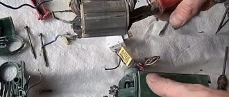
Failure of the rotor in an angle grinder is caused by improper use of the tool, frequent overheating, untimely replacement of carbon brushes, and abrasive particles and dust getting on the collector slats.
First, the length of the spark at the collector increases, then a burning smell appears and, at the last stage, smoke. The operation of a faulty gearbox is accompanied by knocking and humming.
The destruction of even a couple of teeth leads to improper operation of the tool.
You can extend the life of the rotor by preventing dust from getting inside the tool, preventing the tool from overheating, timely changing carbon brushes and lubricants, and using only those working tools and diameters recommended by the power tool manufacturer.
The rotor is a complex assembly that requires repair at service centers. But DIY enthusiasts can repair the rotor themselves.
Repair of commutator and rotor lamellas
Removing the rotor is not particularly difficult.
The procedure for removing the rotor from an angle grinder:
- remove the cover of the grinder handle;
- release and remove the carbon brushes;
- Unscrew the screws securing the gearbox housing to the main body;
- remove the gearbox housing;
- remove the rotor.
The removed rotor must be carefully inspected. If large grooves are rubbed into the lamellas, they should be removed by turning the commutators in a lathe.
For minor grooves, the defect is eliminated by grinding. The rotor is clamped into the chuck of an electric drill and the wear is removed using a file and sanding paper. The process is simple.
The drill is clamped in a vice or securely mounted on a flat surface. The end of the rotor on which the lamella is located is inserted into the drill chuck and clamped securely. The bearings have been previously removed from the rotor.
The second end of the rotor must be supported with a set of wooden blocks. The drill is turned on and a small number of revolutions is set. At the first stage, use coarse sanding paper No. 40..80, and at the final stage use finer grit No. 120..200.
After grinding, you need to mill the grooves between the lamellas. This is best done with a specially sharpened hacksaw blade. After milling the collector grooves, the edges of the lamellas must be cleaned of burrs using a diamond file. Properly ground lamellas should not have burrs.
In addition to general malfunctions in models of angle grinders from different manufacturers, there are also specific breakdowns that are characteristic only of the tool of a given manufacturer. But more on that in another article.
Reading an Electronic Circuit
Unfortunately, there is not much to know about the purpose of the main parts of the electrical circuit of the instrument; you also need to be able to read this circuit. Although the electronic circuit of an angle grinder is not the most complicated thing you can come across among electronic circuits, even here it can be difficult for a person far from electricity to figure it out without outside help.
The main reasons for the malfunction of the angle grinder
First, it is important to understand why the tool stopped working. Perhaps the grinder does not want to turn on due to a fall? Is she stuck in the metal cutting period? Did the sanding disc suddenly stop rotating? Some common reasons why an angle grinder breaks down are:
- Incorrect operation (at high and too low temperatures, prolonged use, overheating of the grinder, etc.).
- Late maintenance or poor repairs.
- Very strong force when working with a tool with concrete, brick, metal.
- Breakage of internal wires, dirt getting inside the instrument, oxidation of contacts.
- Chafing the electrical cord.
