What transistors are used in welding inverters?
Welding is the most popular joining method, which can exist in several variants. The most popular technology is considered to be welding using the inverter method. Despite the high quality of the welding inverter, it happens that due to one reason or another, it becomes faulty. This may require its owner to carry out repairs.
Brief information about inverters for welding
The inverter serves as a source of direct current, which helps ignite and maintain the electric arc that powers the welding process.
The welding process is carried out thanks to a welding current of considerable strength resulting from the operation of a high-frequency transformer.
This fact makes it possible to reduce the size of the transformer itself, increases stability and precise regulation of the output current.
Welding activities are carried out in the presence of a current of the required magnitude, which is obtained in several stages: • Initially, the current received from the network is rectified; • The primary constant current is transformed into a high-frequency current; • The current is increased and at the same time the voltage in the transformer itself is reduced ;
• The output current is rectified for the second time.
Current rectification occurs thanks to diode bridges of a given power. Special transistors help to correctly change the frequency of the current, providing high-frequency transformers with the required output current.
Structure
Inverters for welding activities are represented by several blocks. The power supply itself is responsible for the stability of the output signal.
The multi-winding inductor, the control performed by transistors, as well as the concentration of energy in the capacitor itself are fundamental factors in the control circuit of the unit. As a rule, diodes are involved in throttle control. The power supply is a separate element, separated from other components by a metal partition.
The main element in inverter welding equipment is the power unit. It converts the primary current coming from the power supply into an output current that is directly used for welding.
An electric current of no more than 40A is supplied to the diode bridge, which serves as the primary rectifier. In this case, the voltage fluctuates between 200-250V and a given frequency of 50 Hz.
The inverter converter itself has the form of a power transistor with a power of less than 8 kW, while the voltage is 400 V. The signal itself, which is obtained at the output of the converter, has a frequency of 100 kHz.
The increase in current strength to 200-250A occurs due to the tape windings with which the high-frequency transformer is equipped. With the secondary winding, the voltage readings are no more than 40V.
The secondary rectifier is made up of diodes with a current strength above 250A. Its cooling occurs due to the presence of certain elements, namely:• Fans;• several radiators.
To ensure a stable output signal, a choke is mounted on the output board.
Control units As a rule, the basis of the control unit itself is represented by a master oscillator (in other words, a wide-pulse modulator). If there is a circuit based on the generator itself, a microcircuit can be used.
6-10 capacitors and a working resonant choke are also concentrated on the plateau. Thanks to the transformer, a cascade type of control is carried out.
Resistors and specified capacitors K78-2 serve as the basis for snubbers, which are used in the protective system of converters and rectifiers. The presence of a thermal switch provides high-quality protection of all components in the power unit.
Etiology of breakdowns of inverters for welding
Long-term use of even a high-quality inverter can lead to malfunctions. Breakdowns can occur due to various reasons. For example, due to short circuits in electrical circuits caused by moisture.
Sometimes malfunctions can be caused by the welder’s attempts to perform work that is unacceptable on this equipment.
Malfunctions and their options
Blowing of the fuses themselves can lead to a situation where there is no output current to the inverter, while the proper voltage is available at the input. A breakdown can also result from a violation of the overall integrity of the electrical circuit, which can occur in any part of the inverter.
Another possible malfunction is represented by low welding current readings, despite the highest settings. This situation may arise due to insufficient voltage at the input or due to losses in the contact terminals themselves.
Frequent independent shutdowns of the welding inverter may indicate a short circuit in the electrical network.
Overheating of the components of the power unit can lead to the same effect. In this situation, the protection system may be triggered, which leads to an emergency shutdown.
Carrying out repair activities and their order
If any breakdown is detected, first of all, you should begin an external inspection of the equipment, during which a professional can detect various damage or burns due to a short circuit. Then check the reliability of the electrical cables in the terminals.
Regardless of the inspection results, it is necessary to tighten the cable clamps, for which they use a wrench or a screwdriver. It is advisable to check the integrity of absolutely all fuses using a special tester.
If there is no effect from the previous actions, you need to remove the cover from the inverter housing and inspect the internal contents of the equipment in search of a possible open circuit or traces of a short circuit.
To speed up the identification of the cause of the breakdown, you should measure the output voltage and input current using a multimeter or tester.
If there is no visual damage to the equipment, a unit-by-unit electrical circuit integrity check should be performed. In such a situation, the power supply unit is inspected first, and then the other units.
Power unit and its repair
High-quality repair of faults is possible only if you have a certain set of tools and measuring instruments, namely:• Soldering irons 40V;• Knives;• Pliers;• Wire cutters;• Ammeters for 50 and 250A;• Oscilloscope;• Voltmeters for 50V and 250V;• Soldering irons 40V ;
• Wrench and socket wrench.
When testing the control unit and power unit, special attention should be paid to their elements. A typical breakdown of the power unit is the breakdown of the power transistor, which means that it is advisable to start looking for problems by inspecting it.
Workflow Technology
The presence of mechanical damage on the surface of the transistor may indicate possible damage. The absence of these leads to testing with a multimeter. The transistor malfunction can be eliminated by replacing it with a new device. What is KPT-8 thermal paste used for, which is needed to install it on the plateau.
If the transistor fails to operate, the cause must be sought in a driver failure. Evaluate the operation of these control transistors using an ohmmeter. If non-working parts are found, they are unsoldered and replaced with new ones.
Diode bridges of rectifiers are considered the most reliable in the design of welding inverters, however, this situation cannot be completely eliminated.
When troubleshooting a diode bridge, it is necessary to remove it from the plateau and test its performance by connecting all the diodes together. If the resistance readings are close to zero, then you need to look for a specific faulty diode. Its detection leads to replacement with a new element.
When identifying breakdowns in the control unit, it is necessary to check the parameters of the parts that produce various complex signals. In this case, problems may arise in diagnostics using an oscilloscope, which will require the participation of an experienced specialist.
Power inverter unit
An alternating voltage of 220 V is some average value, which shows that it has the same energy as a direct current of 220 V. In fact, the amplitude is 310 V. Because of this, 400 V capacitors are used in filters.
The bridge rectifier assembly is mounted on the radiator. Cooling of the diodes is required because large currents flow through them. To protect the diodes from overheating, there is a fuse on the radiator; when a critical temperature is reached, it disconnects the bridge from the network.
Electrolytic capacitors with a capacity of 470 μF and an operating voltage of 400 V are used as a filter. After the filter, the voltage is supplied to the inverter.
When switching keys, pulsed current surges occur, causing high-frequency interference. To prevent them from penetrating the network and spoiling its quality, the network is protected with an electromagnetic compatibility filter. It is a set of capacitors and a choke.
The inverter itself is assembled using a bridge circuit. IGBT transistors with voltages from 600 V and currents corresponding to this inverter are used as key elements.
They are also mounted on radiators using special thermal paste. When these transistors switch, voltage surges occur. To suppress them, RC filters are used.
The alternating current obtained at the output of the electronic keys is supplied to the primary winding of a high-frequency step-down transformer. The output of the secondary winding produces alternating current with a voltage of 50-60 V.
Under load, when welding is in progress, it can deliver current up to several hundred amperes. The secondary winding is usually made with tape wire to reduce size.
At the output of the transformer there is another powerful diode bridge. The necessary welding current is already removed from it. Fast-acting power diodes are used here; others cannot be used because they get very hot and fail. Additional RC circuits are used to protect against surge voltages.
Transistors for welding inverters
An inverter should be understood as a direct current source, which ensures the ignition and maintenance of an electric arc.
And, as everyone knows, it is through it that metal welding is performed.
The operation of this equipment is based on the following: welding is carried out using a welding current of considerable strength , which occurs through a high-frequency transformer.
This makes it possible to reduce the size of the transformer, and also improves the stability and ability to adjust the output current.
A number of stages include the process of obtaining the required current strength to perform welding work:
- Primary rectification of electric current received from the network.
- Transformation of primary direct current into high-frequency electric current.
- Increasing the current while simultaneously decreasing the voltage in the transformer.
- Secondary rectification of electric current output force.
The process of current rectification is carried out through diode bridges of a certain power. Powerful transistors are used to change the frequency. A high-frequency transformer provides the required output current.
What transistors are used in welding inverters
Both professional welders and home craftsmen appreciated the principle of operation of the welding inverter, so these devices are gradually replacing traditional welding transformers and rectifiers from the market. And soon the time will come when they will reign in the modern welding equipment market.
What is a welding inverter, why did they appear recently? It should be noted that the principle of inversion, and accordingly the welding unit itself, did not appear yesterday. The basic diagrams of the devices were developed in the 70s of the last century.
But welding instruments appeared in their modern form only recently.
Welding inverter device
Until recently, the inverter device was quite simple in terms of operation. Over time, engineers added electronics to it, which increased the functionality of the unit. The most interesting thing is that this does not make the price of the welding inverter higher. As the sales trend shows, it is gradually decreasing, which makes everyone happy.
Attention! The term "inverter" does not refer to the welding process. This is not a technique. This is the power source of the device.
What is the operating principle of an inverter-type welding machine?
- It operates from an alternating current network with a voltage of 220 or 380 volts and a current frequency of 50 Hz. Plugs into a regular outlet if we are talking about a household welding inverter.
- The welding current entering the inverter passes through the diode bridge, where it is smoothed out and becomes constant.
- The resulting electrical energy passes through a block of transistors (with a high switching frequency), the result is again alternating current only with a higher frequency - 20-50 kHz.
- Next, the current voltage is converted, it is reduced to 70-90 volts at the inverter output. According to Ohm's law, a decrease in voltage results in an increase in current. At the output (at the end of the electrode) there will be a current equal to 100-200 amperes. This is the welding current.
It is the high frequency of current that is the main technical solution in inverter welding machines. It allows you to achieve maximum advantages over other power sources for the electric welding arc.
In inverters, the current required for welding is achieved by changing the high-frequency voltage.
In conventional welding transformers, this process occurs due to a change in the electromotive force (EMF) of the induction coil, which is the main part of the transformer.
It is the preliminary conversion of electricity that allows the use of small-sized transformer units in inverters. For comparison, we can give the following example.
If it is necessary to obtain a current of 160 amperes at the output, then for this you will need to install a transformer weighing 300 g in the inverter.
The same current at the output of conventional welding transformers will be obtained if a transformer with a copper wire (coil) weighing 20 kg is installed in it.
Why is this happening? The main element of a transformer-type welding machine was the power transformer itself with primary and secondary winding coils.
It was the coil that made it possible to reduce the alternating voltage and obtain high currents at the output of the second winding, suitable for inverter welding of metals. A dependence appears from the voltage drop to the current increase.
In this case, the length of the copper wire on the secondary winding decreased, but its diameter increased. Hence the large dimensions of the welding machine and its heavy weight.
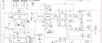
Schematic diagram of the inverter apparatus
In inverter-type welding machines, the opposite is true: they are small in size and weight. But how to obtain high-frequency voltage if its frequency in the network is only 50 Hz? The basic inverter circuit of the device, which consists of powerful transistors, comes to the rescue. They can switch with a voltage frequency of 60-90 kHz.
Technical components
The general structure of operation of such a device is simple, and includes a main current source, an optional rectifier element for the output current, and a common control unit.
A high-quality current source can be completely implemented on the basis of transformer technology or solely on the basis of an inverter system, where power transistors for welding inverters play an important role in the high-quality performance of the device.
For transformer installations, independent manual regulation of the operation of the device is allowed, but among the disadvantages are the rough adjustment mode and the low level of quality of the weld. Inverter installations, on the contrary, having the simplest welding inverter on a single transistor provide high quality weld formation, which is combined with power semiconductor elements.
Transistors for inverters
The main technical components that ensure high quality welding work are the presence of IGBT transistors, as well as universal high-speed diodes. In this case, a reasonable question arises: how to check the IGBT transistor of a welding inverter. We indicate the basic data of transistor components for welding the IGBT version
| Type | Characteristic |
| V | Ultra-low shutdown energy, operation up to 600 V, frequency up to 1200 kHz |
| NV | Low voltage saturated impact principle. Low shutdown energy. Voltage up to 650 Volts, frequency up to 50 kHz |
| N | Low effect of shutdown mode. Supply voltage – up to 1200 volts, frequency up to 35 kHz. |
| M | Low voltage saturation mode, mains voltage up to 1200 Volts, frequency parameter – up to 20 kHz |
| W | Low forward voltage drop mode, and minimal recovery effect mode. |
Features of operation of transistor units
The most common application scheme inside inverters is used using push-pull technology, a bridge operating principle, a half-bridge version of a working inverter, a half-bridge complex asymmetric version of an inverter device, or an oblique half-bridge. Despite the sufficient abundance of topologies, replacing the FGH40N60 transistor in a welding inverter according to general requirements is standard, which includes the following:
- High voltage mode. To effectively replace transistors in welding inverters, the total network voltage must be above 600 Volts.
- Large parameters of switching currents. The average value of the indicator should be at least tens of amperes, and the maximum parameters can show hundreds of amperes.
- High frequency switching mode. Depending on the dimensions of the transformer inside the device, you can increase the frequency of the device, as well as the inductance for the output filter model.
- For the mode of minimizing losses when turning the unit on and off, you can find out how to check the transistors of the welding inverter using a small value of energy supply to the on mode (Evkl), as well as to the shutdown mode (Eukl). In this case, all losses will be minimized.
- To minimize possible losses, we use a low value for the saturation voltage, or Uke us.
- The hard switching effect must be stable for transistors for Resanta welding inverters. In this case, inverter equipment only works with inductive load mode.
- Short circuit parameters. The device must have a resistance mode for this parameter; this information is extremely critical for bridge and half-bridge versions of inverter technology.
How to calculate power loss on IGBT?
We recommend using the diagram below for a detailed calculation of the correct choice of transistor systems.
| Options | Values |
| Total losses | Pd = Pcond + Pswitch |
| Conducted losses | Pcond = Uke us (rms) × Ik × D, where D is the duty cycle |
| Switching losses | Pswitch = Eswitch × f, where f is the switching frequency, Eswitch = (Eon + Eoff) - the total switching losses (given in the IGBT parameters) |
| Maximum power limited by chip overheating | Pd = (Tj – Tc)/Rth-jc, where Tc is the case temperature, Tj is the crystal temperature, Rth-jc is the “chip-to-case” thermal resistance (given in the IGBT parameters) |
All this data will help you correctly calculate the required type of transistor for an inverter welding machine. When choosing a transistor, we must take into account the parameter for the high threshold of the possible operating voltage of the device.
Transistors for welding inverters: technical assessment of condition and repair, expert advice
The most popular joining method is welding. There are several varieties of it. One of the popular ones is inverter welding. A welding inverter is a reliable piece of equipment, but nevertheless situations often arise when it fails.
The reasons why this happens can be very different. If the equipment used for welding has become inoperative, then the owner is faced with the task of repairing it.
General information about inverters
An inverter should be understood as a direct current source, which ensures the ignition and maintenance of an electric arc. And, as everyone knows, it is through it that metal welding is performed.
The operation of this equipment is based on the following: welding is carried out using a welding current of considerable strength , which occurs through a high-frequency transformer.
This makes it possible to reduce the size of the transformer, and also improves the stability and ability to adjust the output current.
A number of stages include the process of obtaining the required current strength to perform welding work:
- Primary rectification of electric current received from the network.
- Transformation of primary direct current into high-frequency electric current.
- Increasing the current while simultaneously decreasing the voltage in the transformer.
- Secondary rectification of electric current output force.
The process of current rectification is carried out through diode bridges of a certain power. Powerful transistors are used to change the frequency. A high-frequency transformer provides the required output current.
Inverter design
Several main blocks have inverter equipment designed for welding work. Stabilization of the output signal is ensured thanks to the power supply.
block control circuit is based on a multi-winding inductor and the presence of control carried out using transistors, as well as the accumulation of energy in a capacitor .
In addition, diodes are used in the throttle control system. The power supply is located separately from other units.
In most models of welding inverters, it is usually separated from other units by a metal partition.
If we talk about the main element of inverter welding equipment, then it is the power unit . It ensures the process of converting the primary current supplied from the power supply to the output welding current, which can be used for welding work.
The diode bridge, to which an electric current of no more than 40A is supplied, is a primary rectifier . The magnitude of the supplied voltage varies in the range from 200 to 250V with a frequency of 50 Hz.
In its appearance, an inverter converter is a power transistor , whose power is less than 8 kW. The operating voltage is at 400V. The converter outputs a signal whose frequency is 100 kHz.
The high-frequency transformer is equipped with tape windings , which ensures an increase in current to 200–250A, and in the secondary winding the voltage does not exceed 40V.
A secondary rectifier is assembled on the basis of powerful diodes with an operating current of at least 250A . Its operating voltage can reach up to 100V. The design provides for the presence of elements that ensure its mandatory cooling:
To ensure stabilization of the output signal, a choke is installed on the output board.
Control units
A master oscillator or wide pulse modulator is used as the basis for the control unit. If a circuit is assembled based on a generator, then a microcircuit is used as it.
In addition to it, a resonant choke is placed on the plateau, and in addition to them there are also capacitors. They are installed in quantities of 6 or 10 pieces. The transformer provides a cascade type control circuit .
In most inverter models, the protection circuit is assembled on the power block plateau to ensure reliable protection of the corresponding element. To effectively protect against overloads when using the equipment, it uses a circuit based on the 561 LA 7 chip .
Snubbers are used in the protection system of rectifiers and converters based on resistors and capacitors K78–2 . Installing a thermal switch allows you to provide reliable thermal protection of the elements of the power unit.
The main causes of malfunction of welding inverters
Even the most modern reliable welding inverter fails after prolonged use. The causes of breakdowns can be very different. Most often this is due to short circuits in electrical circuits . They arise due to moisture getting there.
In some cases, the device becomes faulty due to the welder’s attempts to perform work for which the equipment was not designed.
For example, some specialists use a small-sized welding inverter for cutting railway rails. Solving such a problem with the help of this equipment will, of course, lead to serious overloads and, as a consequence, to equipment failure.
Main types of faults
There are quite a few faults that lead to the inoperability of the welding inverter.
First of all, these are cases when, in the presence of the required input voltage, there is no electric current at the output of the inverter. The occurrence of such a malfunction is associated with blown fuses. In some cases, it may occur due to a violation of the integrity of the electrical circuit , which can appear in any zone of the inverter.
Another type of malfunction is the welding current not reaching the required values even at maximum settings. The main reason for such a malfunction of the welding inverter may be insufficient input voltage . Also, the cause of such a problem may be losses that occur in the contact terminals.
If, when performing work using a welding inverter, spontaneous shutdown of the equipment often occurs, this indicates the presence of a short circuit in the electrical circuit.
This may also indicate severe overheating of the power unit elements. In this case, the protection system can operate in normal mode, thanks to which emergency shutdown is ensured.
The procedure for repairing welding inverter equipment
Regardless of the malfunction encountered by a specialist using a welding inverter, repairs must begin with an external inspection of the unit .
It will help determine the presence of mechanical damage or traces of a short circuit in the form of burns or blackening on the case.
After this, you need to check how securely the electrical cables are fastened in the terminals.
Regardless of the results of the test, you should tighten the cable clamps using a screwdriver or wrench. It would also be a good idea to check the integrity of the fuses using a tester.
If after these manipulations the malfunction is not eliminated, then it is necessary to remove the cover of the inverter equipment housing. After this, you need to carefully inspect the insides of the units in order to identify open circuits. During the inspection process, it is necessary to look for traces of the effects of a short circuit.
To quickly find the cause of the malfunction, you can measure the output voltage, as well as the input current. To carry out measuring work, you must use a tester or multimeter .
If there is no obvious malfunction of the welding equipment, then in this case, block-by-block monitoring of the integrity of the electrical circuit is performed. The test begins with the power supply, gradually moving on to inspecting other units.
Repair of power unit of inverter equipment
To properly troubleshoot problems, you need to thoroughly prepare for repairs, during which a certain set of tools must be used.
When checking and repairing welding inverters, specialists often need to use special tools and measuring instruments:
- pliers;
- soldering irons 40 W;
- screwdriver;
- wrench and socket wrench;
- knife;
- wire cutters;
- ammeter for 50 and 250A;
- voltmeters for 50V to 250V;
- oscilloscope.
After checking the power unit and control unit of the welding inverter, you must first check their main elements. If we talk about malfunctions of the power unit, the most common is the failure of the power transistor . Therefore, troubleshooting in this block should begin with it.
Work technology
You can determine that a transistor is faulty by looking at signs of damage on its surface. If visual inspection does not help determine the condition of the transistor, then you should check its condition using a multimeter. If the transistor fails, it must be replaced with a new one. Installation of a new device on a plateau is carried out using KPT-8 thermal paste.
If a transistor in a welding inverter is faulty, then its inoperative state is accompanied by the failure of one of its drivers. These control transistors should be using an ohmmeter as a performance assessment tool. If faulty parts are found, they must be unsoldered and then replaced with new ones.
In modern models of welding inverters, rectifier diode bridges are the most reliable of the inverter parts in comparison with transistors. But they should also be checked.
In order to accurately determine the cause of the malfunction, it is necessary to remove the diode bridge from the plateau, and then check its condition under conditions of connecting all the diodes to each other. If the resistance readings after checking are close to zero, you need to look for a specific diode that is inoperative. Once detected, this faulty element will have to be replaced with a new one.
Repairing a control unit involves, first of all, checking the parameters of parts that produce complex signals. This can lead to problems in diagnosing faults using oscilloscopes. In such cases, block repairs should be entrusted to specialists .
If, when overheating of the elements of the power unit occurs, the welding inverter does not turn off, then the causes of the malfunction should be looked for in the thermal switches.
In order to determine them, it is necessary to check the reliability of the fastening of the parts on which they control the temperature.
If during testing it turns out that one of the thermal switches does not work, then it is necessary to replace the faulty one with a new one.
Welding specialists often use welding inverters as their main equipment when performing welding work. With prolonged use, even the most modern equipment can break down. In this case, it is necessary to carry out quality repairs .
You can fix minor problems on your own. To do this, you just need to have an understanding of the basics of electrical engineering and have at your disposal a special tool for troubleshooting. Correct diagnosis of the cause of failure of the welding inverter will help to spend a minimum of time on repairs and quickly return it to working condition.
- Nikolay Ivanovich Matveev
Advantages and disadvantages of inverter-type welding machines
Inverter welding machines, which replaced the usual transformers, have a number of significant advantages.
- Thanks to a completely different approach to the formation and regulation of welding current, the weight of such devices is only 5–12 kg, while welding transformers weigh 18–35 kg.
- Inverters have very high efficiency (about 90%). This is explained by the fact that they spend significantly less excess energy on heating the components. Welding transformers, unlike inverter devices, get very hot.
- Due to such high efficiency, inverters consume 2 times less electrical energy than conventional transformers for welding.
- The high versatility of inverter machines is explained by the ability to regulate the welding current over a wide range with their help. Thanks to this, the same device can be used for welding parts made of different metals, as well as for welding using different technologies.
- Most modern inverter models are equipped with options that minimize the impact of welder errors on the technological process. Such options, in particular, include “Anti-stick” and “Arc Force” (fast ignition).
- Exceptional stability of the voltage supplied to the welding arc is ensured by the automatic elements of the inverter electrical circuit. In this case, automation not only takes into account and smoothes out differences in input voltage, but also corrects even such interference as the attenuation of the welding arc due to strong wind.
- Welding using inverter equipment can be performed with any type of electrode.
- Some models of modern welding inverters have a programming function, which allows you to accurately and quickly configure their modes when performing a certain type of work.
Read also: St 101e operating principle
Like any complex technical devices, welding inverters have a number of disadvantages that you also need to be aware of.
- Inverters are highly expensive, 20–50% higher than the cost of conventional welding transformers.
- The most vulnerable and often failing elements of inverter devices are transistors, the cost of which can be up to 60% of the price of the entire device. Accordingly, repairing a welding inverter is quite an expensive undertaking.
- Due to the complexity of their electrical circuitry, inverters are not recommended for use in bad weather conditions and at low temperatures, which seriously limits their scope of application. In order to use such a device in field conditions, it is necessary to prepare a special closed and heated area.
When welding work performed using an inverter, long wires cannot be used, as they induce interference that negatively affects the operation of the device. For this reason, the wires for inverters are made quite short (about 2 meters), which makes welding work somewhat inconvenient.
What transistors are used in welding inverters? – Metals, equipment, instructions
The most popular joining method is welding. There are several varieties of it. One of the popular ones is inverter welding. A welding inverter is a reliable piece of equipment, but nevertheless situations often arise when it fails.
The reasons why this happens can be very different. If the equipment used for welding has become inoperative, then the owner is faced with the task of repairing it.
Transistors for welding inverters: types, characteristics, application, which are better
Technological progress over the past centuries has not been able to ignore welding production. The bulky and inconvenient unit has been replaced by a modern inverter welding machine.
The introduction of electronic systems into the device has made welding work as easy as possible. Now it has become much easier to use welding at home.
The presence of electronics made it possible to include in the device those functions that cannot be applied to older models of transformers. Of course, the fact that electronic elements are used indicates the fact that transistors are used.
Transistor - what is it and what are they?
In this article we will try to answer all these questions as fully as possible. We will describe their differences in more detail and which one is better to give your preference.
Every electronic design uses a transistor. It can be a children's toy or a ground-based aerial surveillance system. This miracle of technology is used in the production of computer equipment, audio and video equipment.
That is, resort to their help in building any microcircuit. The role of the transistor in the inverter is to amplify and control electric current. The invention of the transistor in 1948 provoked a powerful impetus in the evolution of science and technology.
Of course, this led to radical changes in the development of electronics.
The transistor plays a big role in the configuration of small-sized welding machines. An important advantage of them is the ability to work flawlessly at low voltage, as well as at high current.
It is used to generate, amplify, switch and convert electrical signals. A modern inverter weighs no more than 5 kg.
And this is thanks to the introduction of a compact circuit, which was assembled using transistors. This resulted in a reduction in the size of the entire welding machine.
A device with such dimensions greatly simplifies welding work in hard-to-reach places. If we compare the welding machine we are used to, which we used before, and the inverter, then we can say with confidence that the modern device is much easier to learn and use.
Of great importance is the number of additional functions that have been introduced into the device. It is this fact that allows a novice welder to start working without hesitation without risk.
A transistor is a semiconductor device, the main component of a modern welding inverter.
Due to the fact that the inverter is reliably installed in our everyday life, it will be useful to obtain maximum information about its electronic content.
This knowledge will be needed to understand the filling of the welding equipment that you use. Undoubtedly, the presence of many additional functions plays a big role. This allows the less welder to get to work without hesitation.
And since the inverter is reliably installed in our everyday life, it will be useful to get more information about its electronic content. This knowledge will be needed to understand the functions of the equipment you use.
Currently, there are two types of transistors that are used in welding inverters: IGBT and MOSFET. They played a role in reducing the dimensions, and also contributed to the expansion of additional capabilities of the device.
IGBT bipolar transistor
I suggest you pay attention to the bipolar transistor with an insulated gate - this is an IGBT. In fact, these are two transistors on one substrate. IGBT allows you to get high output current with minimal heating.
It is capable of amplifying and generating electrical vibrations. IGBT models began to be used in welding inverters, where there was a need to operate at the highest voltages.
As a result, it became clear that the production of welding machines can be brought to a higher level exclusively with the help of IGBTs.
Very often, for uninterrupted operation of powerful switches, special microcircuits are implanted into the IGBT transistor.
Which is better?
Just above we mentioned another MOSFET transistor. Very often, a dispute arises between welding specialists about which transistor is better. How can we comment on this situation?
There are quite a lot of differences between these two types. True, they are not easy to identify at first glance. MOSFET is a field effect transistor. IGBT is bipolar.
The most important thing is the maximum power that the transistor must withstand. MOSFETs have lower values, while IGBTs have higher power. Naturally, this factor also affects the difference in the cost of the device.
It is interesting that in the characteristics we see many specific differences, but in reality in practice such a difference is not felt. The use of MOSFET transport rather than IGBT does not affect the operation process in any way.
In addition, an IGBT inverter will be much more expensive to maintain. In the event of a breakdown, it is very difficult to find a good repairman and consumables for this device. These factors significantly affect the cost of IGBT.
Therefore, for household welding we recommend a good and inexpensive to maintain MOSFET inverter.
All the value and superiority of IGBTs comes in a device that is designed for high voltage connections. But this is already professional welding work. And here enormous power plays the first role.
In other cases, for amateur welding there is no difference between MOSFET and IGBT. The type of transistor does not matter for beginners. But for a qualified professional it’s still an IGBT inverter.
Although they are more expensive to maintain, they allow you to use more power.
Summarize
At the end of our article, I would like to recommend that a beginner in welding not worry about choosing transistors. A MOSFET is comparatively cheaper to repair and will be much easier for you to get back into working order.
And if you are a welding master, then of course you will need an IGBT inverter to work. Of course, their maintenance will be more expensive, but they have the opportunity to use more power.
In any case, no matter what device you choose, a modern and compact inverter will help you when performing any welding work.
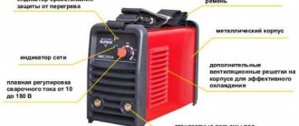
ELECTRONIC COMPONENTS FOR REPAIR AND MANUFACTURE OF WELDING MACHINESAdditional functions will help even an absolute beginner feel like a welding master. Of course, an inverter welding device is much more complex than a classic transformer.
The inverter power source allows you to achieve high quality control of the output parameters of welding machines, and has small dimensions and weight. International Rectifier provides a wide selection of power IGBT transistors and drivers for inverters of various topologies. In addition, the company offers components for constructing the cash register required in this case. Welding is one of the most popular methods of constructively joining materials. It is used in completely different fields: from building construction and aviation to microscopic welding in microelectronics and the jewelry industry. Each of these areas has its own requirements for the types of materials used, the quality of welding, the cost of its implementation, and the level of automation. This has led to the emergence of various technologies, such as manual metal arc (MMA), manual metal inert gas (TIG), semi-automatic metal inert gas (MIG) or active gas welding. (metal active gas, MAG), plasma welding, contact welding and so on. Each of the listed types of welding requires a powerful welding machine that performs the following functions: converts AC mains voltage into direct or alternating voltage and current of the required value, regulates the output parameters of current and voltage, monitors the occurrence of emergency situations, performs additional functions (soft start, etc. similar). There are several types of power sources for welding machines operating from two- or three-phase networks:
- transformer;
- transformer with rectifier;
- inverter
The transformer type involves the use of a network transformer to convert the network voltage to the required level. The output current values can be adjusted by changing the gap between the transformer windings. In this case, the output current has a variable shape. This type of device is the most reliable, but at the same time bulky, and cannot provide a high level of welding quality. The rectifier type differs from the transformer type in the presence of an output rectifier unit. In this case, the welding current is constant. This leads to improved quality of the weld. However, the disadvantages, weight and size, remain. The inverter type is the most modern power source for welding machines. Over the past fifteen years, the characteristics of the semiconductor elements used in such sources, their quality and reliability have increased significantly. Inverter power supplies make it possible to achieve high quality control of welding current parameters, obtain highly stable parameters, and improve weight and size characteristics. The structure of the power supply unit of an inverter welding machine consists of several main components: an input rectifier, a power factor corrector, an inverter, an HF transformer, and a control system (Figure 1). If constant output current is required, an output rectifier can easily be added to the structure. The control system generates a PWM signal for power switches, processes feedback signals from the load, interacts with the operator, detects the occurrence of emergency situations, and so on.
The main element of the presented structure is the inverter. It can be made using any of the existing inverter circuits: bridge, half-bridge, push-pull and others. International Rectifier offers all the necessary components to build highly efficient and reliable inverters based on the most popular circuits: bridge and push-pull. Each of the schemes has its own advantages and features.
IR components for push-pull inverter welding machines
Push-pull topology has long been the main one in the construction of inverters for welding machines. It is distinguished by very important advantages (Figure 2): the need for only two power switches, the simplicity of the control system (the control voltage is generated relative to a common bus and does not require bias), and the potential for cost reduction due to a small number of components. This circuit allows you to obtain both direct and alternating output current.
IR offers IGBTs for implementing various inverter circuits. Among the proposed IGBTs, you can choose the most optimal ones for each specific case. This is possible due to the presence of transistors with different characteristics (Table 1):
- with low switching losses, optimized for high operating frequencies (up to 30 kHz);
- low-frequency, having minimal losses in the on state with a low collector-emitter voltage of 1.46 V (Low VCE(on));
- with short circuit resistance up to 10 µs (index K10);
- with short circuit resistance up to 5 µs (index K);
- with built-in reverse diode (index D).
Table 1. IGBT transistors for the inverter stage of the welding machine
| Name | Voltage, V | Generation | Current IC at 100°C, A | VCE(on) type, V | Switching frequency, kHz | Frame |
| IRGB10B60KD | 600 | Gen5 | 12 | 1,80 | 8…30 | TO-220AB |
| IRGB15B60KD | 15 | TO-220AB | ||||
| IRGP30B60KD-E | 30 | 1,95 | TO-247 | |||
| IRGB4615D | Gen6 | 15 | 1,55 | TO-220AB | ||
| IRGB4620D | 20 | TO-220AB | ||||
| IRGP4620D | TO-247 | |||||
| IRGB4062D | 24 | 1,60 | TO-220AB | |||
| IRGP4062D | TO-247 | |||||
| IRGP6630D | 30 | 1,65 | TO-247 | |||
| IRGP4640D | 40 | 1,60 | Low VCE(on) | TO-247 | ||
| IRGP4063D | 48 | 1,65 | 8…30 | TO-247 | ||
| IRGP4068D | TO-247 | |||||
| IRGP4069D | 50 | 1,60 | TO-247 | |||
| IRGP4078D | 1,90 | Low VCE(on) | TO-247 | |||
| IRGP4650D | 1,60 | TO-247 | ||||
| IRGP6650D | 1,65 | 8…30 | TO-247 | |||
| IRGP4063D1 | 60 | TO-247 | ||||
| IRGP4660D | 1,60 | Low VCE(on) | TO-247 | |||
| IRGP6660D | 1,65 | 8…30 | TO-247 | |||
| IRGP4066D | 90 | 1,70 | TO-247 | |||
| IRGP6690D | 1,65 | TO-247 | ||||
| IRGPS4067D | 160 | 1,70 | Super 247 | |||
| IRGP4262D | 650 | Gen6 | 40 | Low VCE(on) | TO-247 | |
| IRGP4266D | 90 | TO-247 | ||||
| IRGB5B120KD | 1200 | Gen5 | 6 | 2,75 | 8…30 | TO-220AB |
| IRGP20B120UD-E | 20 | 3,05 | TO-247 | |||
| IRGP20B120U-E | TO-247 | |||||
| IRGP30B120KD-E | 30 | 2,46 | TO-247 | |||
| IRGPS40B120U | 40 | 3,12 | Super 247 | |||
| IRGPS40B120UD | Super 247 | |||||
| IRGPS60B120KD | 60 | 2,50 | TO-274AA | |||
| IRG7PH30K10D | Gen7 | 16 | 2,05 | TO-247 | ||
| IRG7PH30K10 | 23 | TO-247 | ||||
| IRG7PH35UD | 25 | 1,90 | TO-247 | |||
| IRG7PH37K10D | TO-247 | |||||
| IRG7PH35U | 35 | TO-247 | ||||
| IRG7PH44K10D | 40 | TO-247 | ||||
| IRG7PH42UD | 45 | 1,70 | TO-247 | |||
| IRG7PH50K10D | 50 | 1,90 | TO-247 | |||
| IRG7PH46UD | 57 | 1,70 | TO-247 | |||
| IRG7PH42U | 60 | TO-247 | ||||
| IRG7PSH54K10D | 65 | 1,90 | Super 247 | |||
| IRG7PSH50UD | 70 | 1,70 | Super 247 | |||
| IRG7PH46U | 75 | TO-247 | ||||
| IRG7PH50U | 90 | TO-247 |
Among the presented transistors, I would like to separately highlight the fairly new IRGx46xxD series, which, having characteristics no lower than those of the “classic” IRGx40xxD series, is more attractive in price (the use of new technologies has made it possible to reduce the cost of transistor production). Also worthy of special attention is one of the newest IGBT series – IRGP66xxD, which combines low conduction and switching losses and was developed by the company specifically for welding equipment. As mentioned above, one of the advantages of the Push-pull topology is the ease of key management. For these purposes, International Rectifier offers two-channel drivers in compact SOIC-8 and DIP-8 packages (Table 2).
Table 2. Low-side drivers for push-pull inverters
| Name | Topology | Inverted inputs | Voltage, V | Output current, Io+, mA | Output current, Io-, mA | Frame |
| IR25600 | Two lower keys | – | 25 | 2300 | 3300 | SOIC-8, DIP-8 |
| IR4426 | INA, INB | |||||
| IR4427 | – | |||||
| IRS4426S | INA, INB | SOIC-8 | ||||
| IRS44262S | ||||||
| IRS4427S | – | |||||
| IRS4428S | INA |
It is worth paying attention to some features of the Push-pull circuit: a more complex transformer, operation of the switches in a more severe mode (higher operating voltage, larger voltage surges). In addition, the presence of only two control arms limits the range of output current regulation. A bridge circuit allows for better regulation.
IR components for bridge inverter welding machines
A bridge circuit, compared to a push-pull circuit, has a larger number of power switches and control components (Figure 3), which makes the circuit as a whole more expensive. However, in most cases this is offset by improved quality of regulation.
It is important to note that to build circuits using both topologies, International Rectifier suggests using the same keys (Table 1). At the same time, in a bridge circuit, power switches operate in more comfortable conditions (lower operating voltage and voltage surges). The complexity of the control circuit in the case of a bridge topology is mitigated by the presence of ready-made half-bridge drivers and upper and lower arms (Table 3). The drivers have built-in biasing and are available in small SOIC and DIP packages.
Table 3. IGBT Drivers for Bridge Inverters
| Name | U, V | Topology | Output current, Io+, mA | Output current, Io-, mA | Separation of power and signal grounds | Frame |
| IR25604 | 600 | Upper and lower key | 200 | 350 | No | SOIC-8 |
| IRS2301 | 200 | 350 | No | SOIC-8, DIP-8 | ||
| IRS2302 | 200 | 350 | No | SOIC-8, DIP-8 | ||
| IRS26072DS | 200 | 350 | No | SOIC-8, DIP-8 | ||
| IRS2607DS | 200 | 350 | No | SOIC-8, DIP-8 | ||
| IRS2101 | 290 | 600 | No | SOIC-8, DIP-8 | ||
| IRS2106 | 290 | 600 | No | SOIC-8, DIP-8 | ||
| IRS21064 | 290 | 600 | No | SOIC-14, DIP-14 | ||
| IRS2112 | 290 | 600 | No | SOIC-14, DIP-14, DIP16 | ||
| IRS2181 | 1900 | 2300 | No | SOIC-8, DIP-8 | ||
| IRS21814 | 1900 | 2300 | No | SOIC-14, DIP-14 | ||
| IRS21814M | 1900 | 2300 | No | PQFN 4 x 4 | ||
| IR25607 | 2500 | 2500 | No | SOIC-8 | ||
| IRS2113 | 2500 | 2500 | No | SOIC-14, DIP-14, DIP16 | ||
| IRS2113M | 2500 | 2500 | No | PQFN 4 x 4 | ||
| IRS2186 | 4000 | 4000 | No | SOIC-8, DIP-8 | ||
| IRS21864 | 4000 | 4000 | No | SOIC-14, DIP-14 | ||
| IRS21867 | 4000 | 4000 | No | SOIC-8 | ||
| IR25601 | Half bridge | 120 | 260 | No | SOIC-8, DIP-8 | |
| IRS2304 | 120 | 600 | No | SOIC-8, DIP-8 | ||
| IR25603 | 180 | 260 | No | SOIC-8, DIP-8 | ||
| IR25606 | 200 | 350 | No | SOIC-8 | ||
| IRS2608DS | 200 | 350 | No | SOIC-8, DIP-8 | ||
| IR25602 | 210 | 360 | No | SOIC-8 | ||
| IRS2103 | 290 | 600 | No | SOIC-8, DIP-8 | ||
| IRS2104 | 290 | 600 | No | SOIC-8, DIP-8 | ||
| IRS2108 | 290 | 600 | No | SOIC-8, DIP-8 | ||
| IRS21084 | 290 | 600 | No | SOIC-14, DIP-14 | ||
| IRS2109 | 290 | 600 | No | SOIC-8, DIP-8 | ||
| IRS21091 | 290 | 600 | No | SOIC-8, DIP-8 | ||
| IRS21094 | 290 | 600 | No | SOIC-14, DIP-14 | ||
| IRS2111 | 290 | 600 | No | SOIC-8, DIP-8 | ||
| IRS2308 | 290 | 600 | No | SOIC-8, DIP-8 | ||
| IRS2183 | 1900 | 2300 | No | SOIC-8, DIP-8 | ||
| IRS2184 | 1900 | 2300 | Yes | SOIC-8, DIP-8 | ||
| IRS21844 | 1900 | 2300 | Yes | SOIC-14, DIP-14 | ||
| IRS21844M | 1900 | 2300 | Yes | PQFN 4 x 4 | ||
| IR2213 | 1200 | Upper and lower key | 1700 | 2000 | Yes | SOIC-16, DIP-14 |
| IR2214SS | Half bridge | 1000 | 1500 | Yes | SSOP-24 |
A household, and even more so an industrial, welding machine is a powerful consumer and a powerful source of interference. For such devices, requirements are established for the power factor and the level of emission of harmonic current components. IR offers all the necessary components for building power factor correctors (PFC).
IR components for constructing PFC welding machines
The main task of constructing power factor correctors is to compensate for phase shifts between the consumed voltage and current while maintaining their sinusoidal shapes. In this case, the power source of the welding machine, from a network point of view, should be as similar as possible to active resistance. Such compensation is mandatory and is established by the requirements of GOSTs (for example, GOST R 51317. 3.2-99 (IEC 61000-3-2-95)). International Rectifier offers a wide selection of both power factor correction controllers and IGBTs optimized for this purpose. PFC controllers are available in small-sized SOIC-8 and DIP-8 packages (Table 4). The IRS2505L is available in a miniature SOT-23-5 package. Important advantages of these controllers are a wide range of supply voltages (up to 22 V), large output currents (peak values up to 1.5 A), and the presence of protective functions.
Table 4. Cash register controllers from International Rectifier
| Name | Frame | Supply voltage, VCC, V | Output peak current, A | Operating frequencies, kHz | Overvoltage protection, OVP | Input Under Voltage Protection, BOP |
| IR1150 | DIP8 | 13…22 | +/-1,5 | 50…200 | – | – |
| IR1150S | SOIC-8 | 13…22 | +/-1,5 | 50…200 | – | – |
| IR1152S | SOIC-8 | 14…17 | +/-0,75 | 66 | Double | + |
| IR1153S | SOIC-8 | 14…17 | +/-0,75 | 22 | + | + |
| IR1155S | SOIC-8 | 12…20 | +/-1,5 | 48…200 | + | – |
| IRS2500S | SOIC-8 | 12,5…20 | +/-0,5 | 20…800 | + | – |
| IRS2505L | SOT-23-5 | 12…20 | +0,05/-0,045 | Variable | + | + |
Transistors used for PFC must have high speed in order to cope with the resulting current and voltage offsets. They must also be resistant to overvoltage and remain operational under the most severe switching conditions. All these requirements are met by the corresponding IGBTs from International Rectifier (Table 5).
Table 5. IGBT transistors for PFC from IR
| Name | Voltage, V | Current IC at 100°C, A | VCE(on) typ., V | Switching frequency, kHz | Frame |
| IRG4IBC20W | 600 | 6 | 2,16 | 30…150 | TO-220 FullPak |
| IRG4BC20U | 6,5 | 1,85 | 8…30 | TO-220AB | |
| IRG4BC20W | 2,16 | 30…150 | TO-220AB | ||
| IRG4BC20W-S | D2-Pak | ||||
| IRG4IBC30W | 8,4 | 2,10 | TO-220 FullPak | ||
| IRGR4610D | 10 | 1,70 | 8…30 | D-Pak | |
| IRG4BC30U | 12 | 1,95 | TO-220AB | ||
| IRG4BC30W | 2,10 | 30…150 | TO-220AB | ||
| IRG4BC30W-S | D2-Pak | ||||
| IRG4PC30U | 1,95 | 8…30 | TO-247 | ||
| IRG4PC30W | 2,10 | 30…150 | TO-247 | ||
| IRGS4615D | 15 | 1,55 | 8…30 | D2-Pak | |
| IRGB4061D | 18 | 1,65 | TO-220AB | ||
| IRGS8B60K | 19 | 1,80 | D2-Pak | ||
| IRG4BC40U | 20 | 1,72 | TO-220AB | ||
| IRG4BC40W | 2,05 | 30…150 | TO-220AB | ||
| IRG4BC40WL | TO-262 | ||||
| IRG4BC40WS | 2,05 | D2-Pak | |||
| IRG4PC40U | 1,72 | 8…30 | TO-247 | ||
| IRGB4620D | 1,55 | TO-220AB | |||
| IRGP4620D | TO-247 | ||||
| IRGB20B60PD1 | 22 | 2,50 | 30…150 | TO-220AB | |
| IRGP20B60PD | TO-247 | ||||
| IRGB4062D | 24 | 1,60 | 8…30 | TO-220AB | |
| IRGS4062D | D2-Pak | ||||
| IRGSL4062D | TO-262 | ||||
| IRGP35B60PD | 34 | 2,25 | 30…150 | TO-247 | |
| IRGP4640D | 40 | 1,60 | 8…30 (Low VCE(on)) | TO-247 | |
| IRGP50B60PD | 42 | 2,00 | 30…150 | TO-247 | |
| IRGP4078D | 50 | 1,90 | 8…30 (Low VCE(on)) | TO-247 | |
| IRGP4650D | 1,60 | TO-247 | |||
| IRGP4660D | 60 | TO-247 | |||
| IRGP4266D | 650 | 90 | 1,70 | TO-247 | |
| IRG4PF50WD | 900 | 28 | 2,25 | 30…150 | TO-247 |
| IRG7PH46U | 1200 | 75 | 1,70 | 8…30 | TO-247 |
Conclusion
International Rectifier offers all the necessary basic components to create power supplies for inverter welding machines. Among the company's proposals it is worth noting:
- powerful IGBTs for the main stage of the inverter, capable of operating at frequencies up to 30 kHz and withstanding harsh switching conditions, including in the Push-pull topology;
- dual-channel low-side IGBT drivers for push-pull topology;
- dual-channel half-bridge and high- and low-side IGBT drivers for bridge topology;
- PFC controllers with a wide range of supply voltages and a high level of protection;
- ultra-fast IGBTs designed for harsh operating conditions as part of PFCs.
Literature
- David G.Morrison. Semiconductors Spark Advances In Welding Power. Electronic Design, 2001;
- A. Roccaro, R. Filippo, M. Salato. AN-1045. AC TIG Welding: Output Inverter Design Basics. International Rectifier, 2003;
- https://www.irf.com/.
Site administration address