An example of solving the problem of a complete calculation of the strength and stiffness of a steel I-beam for a given system of bending loads.
Task
Perform a full strength calculation and check the rigidity of a statically determinate I-beam with two supports (Fig. 1) with the following data: F=40kN, q=30 kN/m, a
=0.8 m,
l
=4m, permissible normal and tangential stresses: [σ]=160 MPa and [τ]=100 MPa, permissible beam deflection [f]=
l
/400
Rice. 1
More sample solutions > Help with problem solving >
Solution
Construction of diagrams Q and M
A detailed example of constructing diagrams of transverse forces Q and bending moments M for a beam
Internal force factors Qy and Mx in the beam span 0 ≤ z2 ≤ l
QII= — RB+ qz2= -52+30∙z2 QII(z=0)= -52 kN QII(z=l)= -52+30∙4=68 kN
MII=RB∙z2-qz22/2=52z2-30∙z22/2 MII (z=0)= 0 MII (z=l)= -32 kNm
On the console l ≤ z1≤ (l+a)
QI= — RB+ ql — RA=-52+30∙4-108=-40 kN
MI=RB z1-ql(z1-l/2)+RA(z1-l)=52z1-30∙4(z1-4/2)+108(z1-4) MI (z=l)= -32 kNm MI (z=l+a)= 0
Based on these data, diagrams of Q and M were constructed.
Strength condition for an I-beam
So, the strength condition for flat bending will look like this:
In the inequality on the left, the maximum design stress is written, and on the right, the permissible stress.
The maximum design stress, in strength data, is found in two ways:
As the ratio of the maximum bending moment to the moment of resistance:
Or using this formula:
Where M is the maximum bending moment, y is the distance from the neutral line to the extreme point of the section, J is the moment of inertia of the section.
The moment of inertia and the moment of resistance are related as follows:
Selection of the cross-section of an I-beam
Since Mmax = 45 kNm, then
Wx≥Mmax / [σ] = 45∙103 / 160∙106= 0.281 m3= 281 cm3
.
How to select a beam section
According to the assortment, we select I-beam No. 24, for which Wx = 289 cm3, Ix = 3460 cm4, Smax = 163 cm3, h = 24 cm, bп = 11.5 cm, t = 0.95 cm, d = bc = 0.56 cm, h0 = h-2t = 22.1 cm.
This I-beam will operate at the maximum normal stress in the extreme fiber of the dangerous section.
σmax = Mmax / Wx = 45∙103 / 289∙10-6= 156∙106 Pa = 156 MPa
Calculation of beam deflections
Let's see how to use the initial parameters method using the example of a simple beam, which is loaded with all kinds of loads, in order to maximally cover all the subtleties of this method:
Support reactions
To make the calculation, you need to know all the external loads acting on the beam, including the reactions occurring in the supports.
If you don’t know how to determine reactions, then I recommend studying this material, where I tell you how they are determined using the example of this beam:
Coordinate system
Next, we introduce a coordinate system with the origin on the left side of the beam (point A):
Distributed load
The initial parameters method, which we will use a little later, only works when the distributed load reaches the rightmost section, the one farthest from the origin of the coordinate system. Specifically, in our case, the load breaks and such a design scheme is unacceptable for further calculations.
If the load were applied like this:
Then we could immediately begin calculating displacements. We will need to use one tricky trick - introduce additional loads, one of which will continue the existing load q, the other will compensate for this artificial continuation. Thus, we obtain an equivalent design scheme, which can already be used in the calculation using the initial parameters method:
Here, in fact, are all the preparatory steps that need to be done before the calculation.
Let's proceed directly to the calculation of the beam deflection itself. Let's consider the most interesting section in the middle of the span; it is obvious that this section will bend the most and when calculating the rigidity of such a beam, this particular section would be calculated. Let's call it the letter C:
We write down the boundary conditions relative to the coordinate system. Taking into account the method of securing the beam, we fix that the deflections at points A and B are equal to zero, and the distances from the origin to the supports are important:
\[ { V }_{ A }=0\quad at\quad x=0 \]
\[ { V }_{ B }=0\quad at\quad x=8m \]
We write the equation of the initial parameters method for section C:
\[ E{ I }_{ z }{ V }_{ C }=… \]
The product of the beam stiffness EI and the section deflection C will be the sum of the product EI and the section deflection at the origin of the coordinate system, that is, section A:
\[ E{ I }_{ z }{ V }_{ C }=E{ I }_{ z }{ V }_{ A }+ … \]
Let me remind you that E is the modulus of elasticity of the first kind, depending on the material from which the beam is made, I is the moment of inertia, which depends on the shape and dimensions of the cross section of the beam. The angle of rotation of the cross section at the origin of the coordinate system is also taken into account, and the angle of rotation is additionally multiplied by the distance from the section in question to the origin of coordinates:
\[ E{ I }_{ z }{ V }_{C }=E{ I }_{ z }{ V }_{ A }+E{ I }_{ z }{ \theta }_{ A } \cdot 4+… \]
Accounting for external load
And finally, you need to take into account the external load, but only that which is located to the left of the section C under consideration. There are several features here:
- Concentrated forces and distributed loads that are directed upward, that is, coincide with the direction of the y-axis, are written in the equation with a plus sign. If they are directed in the opposite direction, respectively, with a minus sign:
- Moments directed clockwise are positive, counterclockwise are negative:
- All concentrated moments need to be multiplied by the fraction:
\[ M\cdot \frac { { x }^{ 2 } }{ 2 } \]
- All concentrated forces need to be multiplied by the fraction:
\[ F\cdot \frac { { x }^{ 3 } }{ 6 } \]
- The beginning and end of distributed loads must be multiplied by a fraction:
\[ q\cdot \frac { { x }^{ 4 } }{ 24 } \]
Where did these numbers and degrees come from? All these things follow when integrating the differential equation of the elastic line of a beam; in the method of initial parameters, all these conclusions are omitted, that is, it is, as it were, a simplified and universal method.
Deflection formulas
Taking into account all the rules described above, we write the final equation for section C:
\[ E{ I }_{ z }{ V }_{ C }=E{ I }_{ z }{ V }_{ A }+E{ I }_{ z }{ \theta }_{ A } \cdot 4+\frac { { R }_{ A }\cdot { 4 }^{ 3 } }{ 6 } -\frac { F\cdot { 4 }^{ 3 } }{ 6 } -\frac { q \cdot { 2 }^{ 4 } }{ 24 } \]
This equation contains 2 unknown quantities - the desired deflection of the section C and the angle of rotation of the section A.
Therefore, in order to find the deflection, we will compose a second equation for section B, from which we can determine the angle of rotation of section A. At the same time, we will fix the material passed through:
\[ E{ I }_{ z }{ V }_{ B }=E{ I }_{ z }{ V }_{ A }+E{ I }_{ z }{ \theta }_{ A } \cdot 8+\frac { { R }_{ A }\cdot { 8 }^{ 3 } }{ 6 } -\frac { F\cdot { 8 }^{ 3 } }{ 6 } -\frac { q \cdot 6^{ 4 } }{ 24 } +\frac { q\cdot 2^{ 4 } }{ 24 } =0 \]
Let's simplify the equation:
\[ E{ I }_{ z }{ \theta }_{ A }\cdot 8+874.67=0 \]
Expressing the angle of rotation:
\[ { \theta }_{ A }=-\frac { 874.67 }{ 8E{ I }_{ z } } =-\frac { 109.33 kN{ m }^{ 2 } }{ E{ I }_{ z } } \]
We substitute this value into our first equation and find the desired displacement:
\[ E{ I }_{ z }{ V }_{ C }=\frac { -109.33\cdot 4E{ I }_{ z } }{ E{ I }_{ z } } +\frac { { R }_{ A }\cdot { 4 }^{ 3 } }{ 6 } -\frac { F\cdot { 4 }^{ 3 } }{ 6 } -\frac { q\cdot { 2 }^{ 4 } }{ 24 } =-\frac { 280kN{ m }^{ 3 } }{ E{ I }_{ z } } \]
Checking the beam section using tangential stresses
Since Qmax = 68 kN, then
Construction of diagrams of normal σ and tangential τ stresses in an unfavorable section of the beam:
Constructing a diagram of normal stresses
Constructing a diagram of tangential stresses
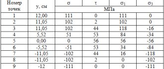
In terms of principal stresses, the section above the left support is unfavorable, in which:
M = -32 kNm and Q = 68 kN.
The stress values at various points along the I-beam height are summarized in Table 1
Table 1
Calculation results in the example
What is beam deflection?
Under the influence of an external load, the cross sections of the beam move vertically (up or down), these movements are called deflections. Strength material allows us to determine the deflection of a beam, knowing its geometric parameters: length, cross-sectional dimensions. And you also need to know the material from which the beam is made (elastic modulus).
By the way! In addition to vertical movements, the cross sections of the beam are rotated at a certain angle. And these values can also be determined by the method of initial parameters.
ν-deflection of section C; θ is the rotation angle of section C.
Beam deflections must be calculated when calculating rigidity. The calculated values of deflections should not exceed the permissible values. If the calculated value is less than the permissible value, then it is considered that the rigidity condition of the structural element is met. If not, then measures are taken to increase rigidity. For example, they are set by another material, which has a GREATER elastic modulus. Or they change the geometric parameters of the beam, most often the cross section. For example, if an I-profile beam No. 12 is not suitable in terms of rigidity, I-beam No. 14 is accepted and a recalculation is made. If necessary, repeat the selection until they find the right one - the I-beam.
Calculator
| Calculation example |
Related calculators:
- Collection of loads on floor beams online
- Calculation of a rectangular pipe
- Square pipe calculation
- Channel calculation
- Angle calculation
- Calculation of a wooden beam
- Calculation of I-beam stability.
Types of beams used in construction
The modern construction industry, when constructing industrial and residential structures, practices the use of rod systems of various sections, shapes and lengths, made of various materials.
The most widespread are steel and wooden products. Depending on the material used, determining the deflection value has its own nuances related to the structure and uniformity of the material.
Wooden
Modern low-rise construction of individual houses and country cottages makes extensive use of logs made from softwood and hardwood.
Basically, wooden products that work in bending are used for arranging floors and ceilings. It is these structural elements that will experience the greatest lateral loads, causing the greatest deflection.
The deflection of a wooden log depends on:
- From the material (wood species) that was used in the manufacture of the beam.
- From the geometric characteristics and shape of the baked section of the design object.
- From the combined action of various types of loads.
The criterion for the permissibility of beam deflection takes into account two factors:
- Compliance of the actual deflection with the maximum permissible values.
- Possibility of operating the structure in the presence of a design deflection.
Steel
They have a more complex cross-section, which can be composite, made from several types of rolled metal. When calculating metal structures, in addition to determining the rigidity of the object itself and its elements, it often becomes necessary to determine the strength characteristics of the connections.
Typically, the connection of individual elements of a steel structure is carried out:
- Using electric welding.
- By using threaded (stud, bolt and screw) connections.
- Connection with rivets.
Examples of calculated resistance
To calculate an I-beam, a value such as design resistance (Ry) may be required. It depends on the grade of steel from which the beam is made. For example, here are the ready-made values:
- C 235 – 230 MPa;
- C 345 – 335 MPa;
- From 255 – 250 MPa.
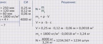
The elastic modulus is taken as one value, equal to steel: E = 200,000 MPa. The calculation of the load of an I-beam is carried out on the basis of load-bearing capacity calculations. To this figure add 30% for strength (this applies only to welded profiles).
How to replace calculating deflection?
When building a small house in private construction, it is not necessary to find all the values for complex calculations. Some parameters may not affect the quality of construction at all. For example, for a small house or dacha, one of two values is determined:
- Deflection of an I-beam;
- Load bearing capacity.
At the same time, it is not necessary to calculate deflection in private construction. However, its value is used when choosing a finish for the ceiling, since it is better not to use heavy materials under unfavorable conditions.