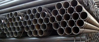
Today, construction technologies are so reminiscent of the futuristic future that literally tomorrow houses will begin to be built from transparent concrete using another 3D printer. Even experienced professionals do not always have time to keep up with all the new products. And, although some of these materials have been used on the domestic market for a long time, they still have not become recognizable.
Thus, an I-beam made of wood or metal is considered quite underrated today. But strong floors and entire rafter systems are made from it! Moreover, such a beam has a number of advantages over conventional elements. But why is it still not in every home?
Because many are confused by its fragile appearance due to its thin internal rib. Although in fact the laws of physics work perfectly here, and in the right position the I-beam is in no way inferior to much more massive and heavy beams. How can this be? And now we will tell you!
What is an “I-beam”?
For many companies today, the priority is to build reliable and inexpensive houses, and in a relatively short time. And these problems are solved to a greater extent by the building materials used.
Until recently, the I-beam in Russia was used only in the industrial sector, but today it is becoming more and more popular. The emergence of new types of I-beams in recent years has made it possible to successfully use them in the construction of ordinary residential buildings.
In construction, an “I-beam” is a wooden or metal profile that has a cross-section similar to the letter “H”. The term itself comes from “taurus,” which means “bull horns.”
The assortment of I-beams on the domestic market is still small, because the product itself is still little known and few manufacturers represent it. But abroad, quite interesting types of it are used, where engineering thought and the laws of physics are combined.
How to find out the exact weight of a construction I-beam?
An important part of metal fabrication that needs to be mentioned from a technical perspective is calculating the weight of the I-section used for each project. The calculation is based on the profile number, which can be found in the assortment of I-beams, where you can also see the mass and cross-sectional area. It is worth paying attention that the table shows the mass of one linear meter.
In order to find out the weight of an I-beam, you can weigh the material.
It is important to understand that this procedure is carried out only during the shipment of the construction I-beam in order to find out exactly how much the supplier is releasing to the customer.
However, there are some cases when weighing beams is not possible in principle. In this situation, mathematical calculations will help. To do this, take individual I-beams and calculate them by multiplying the length by the weight of one linear meter. It is important to understand that the entire footage of the product in such specific cases can be found out by measuring the length. The specific gravity of an I-beam metal structure is calculated using one of the following methods:
- Look at the values of the characteristics specified in the table of the state standard.
- Calculated manually.
It is worth knowing that the values of the linear meter of the beam were determined manually using calculation methods. Calculations were used for beams with a nominal size, and the metal density was taken to be absolutely identical to the average value. Real materials are often produced in slightly different sizes than the base ones. It is precisely this difference that is allowed according to GOST, and is called the maximum possible deviations during production.
Advantages and disadvantages of I-beams
Let's list the main features of I-beams. And there are a lot of them!
Thanks to its special design, an “H”-shaped beam is in practice 7 times stronger than a standard square beam with the same cross-sectional area, and at the same time 30 times stiffer. Amazing, isn't it?
At the same time, an I-beam with an open cross-section (like an angle or a channel) has low resistance to torsion , 400 times less than a round pipe. Therefore, the load, constant and variable, must be calculated on the I-beam that will be used.
The constant assumes the weight of the material in the form of beams, insulation, floor and ceiling, and the variable assumes the weight of people and equipment on the floor. As a result of such precise calculations, the strength of the I-beam is beyond doubt.
During operation, the dimensions of I-beams remain stable and are not subject to shrinkage . The load-bearing capacity of such beams is up to 500 kg per linear meter, and one linear meter weighs only about 6.8 kg.
Thanks to all this, such beams are suitable for fairly long runs, up to 24 meters, and their installation does not require special lifting mechanisms (although with them, of course, all work goes faster).
By the way, I-beams differ favorably from trusses in that they are easy to trim if necessary , whereas this cannot be done with trusses.
The beams are quite light and convenient, they can be transported without problems:
Plus, the use of such beams affects how expensive and heavy equipment will need to be brought to the construction site, at what temperatures it is allowed to work, and how much the ceiling itself will weigh.
As for the price, we note that standard plank flooring, of course, is cheaper . But it is worth considering that the boards themselves additionally require intermediate supports, sheathing and many other additional parts. In addition, such a base periodically needs repairs, because we are talking about wood.
To summarize: I-beams are excellent as rafters, purlins and floor beams, as well as frame elements in low-rise construction.
Features of I-profile
I-beam is a type of rolled metal. The I-beam profile is characterized by an H-shaped cross-section. This design is used to redistribute the load vertically and horizontally. I-beams of various sizes and weight categories.
To designate profiles, special numbering and markings have been introduced, which facilitates the selection of a structural element. Since when choosing the dimensions of the beam, the features of the object being built and the design loads on the building structure are taken into account.
Beams are characterized by resistance to increased loads and lack of response to changes in the external environment.
Due to its characteristics, I-beams are widely used in the construction of frame buildings and structures.
In addition to metal I-beams, there are beams made of wood, which also have a varied range of sizes. The use of wooden profiles reduces the load on the foundation, speeds up the construction process and reduces costs when constructing a foundation.
Wooden I-beams for low-rise construction
Wooden I-beams are most actively used today as load-bearing elements of floors and truss structures for buildings. Wooden I-beams are suitable for brick, timber, block and log houses.
Technical characteristics: strength and weight
Wooden I-beams are made from laminated lumber. Both belts are made of wooden blocks, which are fastened with OSB or a wood fiber insert.
Abroad, such beams are made from OSB and HDF, and in Russia there are several factories that produce such beams from OSB and plywood walls, the quality of which, however, still remains questionable.
Let's take a closer look at the technical characteristics of such I-beams:
This is what an I-beam rafter system looks like:
The very formula “wood + OSB + wood” allows you to avoid many of the disadvantages that you cannot do without when you have to use a solid wooden beam.
Comparison with other building materials
Let's list the main advantages of such beams. They are straight, because completely devoid of bending moments, because OSB will no longer “lead”. At the same time, the beams are quite strong and easy to install, because No special skills are required to install them.
Here is a comparison of a wooden I-beam and a regular edged board according to the main indicators:
Further, compared to wood, I-beams weigh much less, cover large spans perfectly and do not change their geometry over time.
At the same time, ordinary wooden beams run the risk of cracking, torsion and shrinkage:
Thanks to its special properties, the wooden I-beam is so rigid that it can span large spans without any intermediate supports.
Thus, gable beams and beams with parallel chords are used for load-bearing floors with spans from 6 to 15 meters! In this case, office and residential premises are quite spacious, which is especially fashionable today.
Moreover, these advantages are especially valuable when compared with materials that are more familiar on the Russian market. And the main advantage here is the weight of the I-beam:
By the way, I-beams are not used simultaneously with ordinary timber, because their shrinkage rates differ significantly. As a result, if you combine both types of material, after a year or two the ceiling will lose its horizontality, and the walls will no longer have even support.
Manufacturing materials: shelves and walls
The top and bottom chords of I-beams are made of solid or special modified wood, and the vertical filling is made of OSB or plywood.
The secret of all these advantages is that in the manufacture of I-beams, wood with a moisture content of no more than 18% is used. For this, two-component glue and stiffeners made of high-quality oriented strand boards are used, so such beams do not have problems with creaking or uneven floors.
High-quality beams do not lose their valuable physical properties due to changes in temperature and humidity, and cutting and adjusting I-beams is not difficult with the most common carpentry tools.
The bars in this design must be of a solid cross-section, and the joints must be made with a toothed tenon, which is made with a special cutter. Next, the wall is glued into the grooves of the beam chords. Stiffening ribs are installed at the ends of the beams. Next, the beams are protected with antiseptic coating or spray solution.
OSB is made from flat wood chips by pressing, and the chips, usually from softwood, are bonded with synthetic resins. Thanks to all this, the stove has high water-resistant characteristics. After all, here the pieces of wood seem to be intertwined and create a durable material without stress concentrators (in a word, homogeneous, identical along the entire length).
The material turns out to be of much higher quality than ordinary plywood. And at the same time even more elastic, thanks to which it perfectly holds construction staples, nails, screws and other elements.
Using such a framework has its advantages. Thus, natural lumber is not without its drawbacks; its quality is quite difficult to determine by eye. At the same time, artificial beams are as reliable and accurate as possible.
They have no defects, knots or deformations, they do not crack or rot. Structures obtained from such materials are called shape-stable. They do not creak like wood, they are more durable and rigid. Their production requires less natural raw materials and fewer requirements for its quality.
Here is a very interesting video on making wooden I-beams with your own hands:
Also, wooden I-beams are produced with a plywood wall. The shelves here are made of rectangular wooden blocks, with a wavy wall made of special waterproof plywood.
Although for many craftsmen, the word “plywood” in the interfloor ceiling causes horror. After all, we are talking about a colossal load! In fact, the laws of physics are at work here, namely the principle of pressure: try placing a piece of plywood on its edge, and see how strong such a position can be.
You've probably wondered why you can't use a regular board as a wall, especially since it's stronger than plywood or OSB?
In fact, such materials are hot-pressed during the production process, and therefore have a much higher density than ordinary wood. However, the board is indeed sometimes used, but only of dense wood, after professional deep impregnation and in more rare cases.
Series and types: modern range
The assortment of the I-beam indicates the characteristics of the beam: height, thickness and width of each element. So. wooden I-beams have the following types:
- “ BDK ” is a glued I-beam with a wide flange, designed for short spans.
- “ BDKU ” is a reinforced beam with a wide flange for long spans.
- “ BDKSH ” is a wide beam for rafter systems, loaded structures and especially long spans.
- " SDKU " is a reinforced beam for a wall frame.
- “ SDKSH ” is a wide stand for constructing a wall frame.
All of these options also have subtypes:
Sometimes, for some projects, I-beams are made in pairs, thereby increasing their rigidity:
By the way, there is another variation of a wooden I-beam: the beam belt is made of dry coniferous wood, and the connecting lintel is made of galvanized high-strength steel with a special polymer coating.
The wooden parts of the beam must be treated with a fire-retardant composition, because here there is contact between metal and wood.
Features of application and installation
The use of such beams is quite simple:
In real life, such a setup looks like this:
We also note that OSB beams have high strength and a convenient design, which allows you to carry out the necessary utilities directly in the floors.
I-beam 14: dimensions and design features
I-beam profile No. 14 is manufactured in accordance with the provisions prescribed in GOST 8239-89. It is recommended for use in the construction of load-bearing structures in industrial and residential buildings, in the construction of bridges, as well as in the mechanical engineering industries. The material demonstrates high resistance to adverse environmental influences, fire resistance, and is also not afraid of various types of microorganisms. With the help of such structures it is possible to achieve a reduction in installation costs and a reduction in construction time.
I-beam 14, the dimensions of which are ideal for use in the construction of floors, is used in the creation of reinforced concrete structures with moderate and slightly increased loads.
The total height of this profile (including the thickness of the shelves) is 140 mm. The beam has a width of 73 mm, the lintel wall is 4.9 mm. The total thickness of the shelf reaches 7.5 mm. The weight of a meter I-beam is 13.68 kg. There are different types of I-beam of this type.
I-beam table No. 14 clearly demonstrates this:
| Profile view | Width, mm | Height, mm | Shelf thickness, mm | Wall thickness, mm | Weight of 1 m length, kg |
| 14 | 73 | 140 | 7,5 | 4,9 | 13,68 |
| 14C | 80 | 140 | 9,1 | 5,5 | 16,9 |
| 14B1 | 73 | 137,4 | 5,6 | 3,8 | 10,5 |
| 14B2 | 73 | 140 | 6,9 | 4,7 | 12,9 |
Steel I-beams for powerful buildings
Today, space-planning solutions can be so complex that it is impossible to do without load-bearing steel beams, because with spans of 7 meters or more, no concrete structures are effective.
Unlike a wooden one, a metal I-beam spans spans with a significant load, does not burn and is resistant to biological influences (mold, bugs). True, in the event of a fire, over time it can lose its load-bearing capacity, as well as corrode in the absence of protection. In addition, the metal I-beam is heavy and cannot be installed without special equipment.
But steel beams are not used for the construction of attic floors of houses, the foundations of which have a maximum load. Also, such beams will be quite heavy for walls made of porous, cellular materials and profiled timber, which shrinks over time.
Types of steel for making beams
I-beams today are made from rolled steel, aluminum alloys and cast steel. In this case, steel is an alloy of iron and carbon, with only small impurities and alloying additives. The most popular in this regard is low-carbon.
The steel itself may also differ in the production method, for example, into calm, boiling and semi-calm. And, depending on the properties of steel, it is made into regular steel and with increased or high strength.
Thus, low-carbon steels are steels of medium strength, and low-alloy steels already have increased strength. The strongest is medium alloyed.
Welded and rolled I-beams: what is the difference?
According to the type of section, steel beams can be rolled or composite, connected by welding. Hot rolling of beams is carried out on rolling machines - special installations with rotating rollers. To do this, take a thick ingot, which is moved along a roller table and the beam takes the shape of an I-beam.
During the rolling process, the ingots are moved along a roller conveyor and processed by a series of rolls, as a result of which the length of the workpieces increases greatly, and the cross-section gradually decreases and takes on the shape of an I-beam. This is a fairly productive method, but due to the use of complex equipment, it is not cheap.
But welded I-beams are produced on automated lines. To do this, blanks are cut, I-beam profiles are assembled and they are submerged. After this, the profiles will be further processed by rolling to achieve the ideal geometry of the shelves.
Next, the surface of the profile is cleaned and a protective coating is applied. Only with the help of welded technology is it possible to produce beams with the most accurate dimensions, thin-walled and multi-flange I-beams.
Welded beams are lighter, up to 30% lighter than hot-rolled ones, and are good because they allow you to use different types of steel in one structure. For example, there is one for shelves and another for walls.
Thus, the most stressed areas in it are made of high-strength steel, and the less stressed areas are made of low-carbon steel. This approach reduces the cost of the beam by 5%.
The beams themselves, in which several different grades of steel are used simultaneously, are called bistal. It’s simple: the walls in the beam are least loaded, and the chords are the most loaded. In the belts, steel of higher strength is used, and this is 14G2, 10G2S1.
By the way, the use of bistal I-beams is most appropriate for static loads. And compared to beams made of single steel, these will cost 5-15% less.
In itself, rolling such profiles is more productive than welding, but welded beams are easier to produce with the required parameters. For example, only the welding method can make beams 4 meters or more high.
Design features of steel I-beams
A metal I-beam is often made of different sections. For what? The fact is that the beam itself experiences different stresses along its length during its operation, and in some places it is significantly lower than the permissible one.
In addition, for different tasks, a certain bending of the beam walls is allowed. Which, by the way, cannot be done with a wooden I-beam. The curvature of the beam walls is calculated using the following formula:
Another popular method is to concentrate the metal in the ribs and reduce the wall thickness (this technique provides savings of 10-20%).
It turns out that in such places you have to use more metal than necessary, and this is already an overrun. Therefore, profiles with a variable cross-section are sometimes made in order to save money, although most beams have a profile that is constant along its entire length.
Series and numbers of steel I-beams
Metal I-beams have different purposes, and therefore their characteristics may differ. Thus, beams with parallel flanges are marked as follows:
- “ Sh ” are I-beams with wide flanges that can withstand significant loads.
- " U " - beams with narrow flanges for residential construction.
- “ D ” - I-beams with middle flanges.
- “ K ” - beams, specially produced for the construction of columns, are quite heavy and durable.
Based on the angle of inclination, beams are divided into the following types:
- “ M ” is a beam with inclined shelves for the construction of suspended tracks. Here the angle of inclination does not exceed 12%. At the same time, 12% and 16% are the maximum for the internal corner.
- “ C ” is an I-beam for strengthening mine shafts, with an angle of inclination of the edges of up to 16%.
According to the degree of accuracy, I-beams are classified as follows:
- “ B ” is a beam of normal manufacturing precision. Suitable for most construction tasks.
- “ B ” are high-precision products, specially designed for complex tasks where the smallest errors matter.
According to the shape of the shelves, metal I-beams are made in two types - with a slope of the internal edges of the shelves or with parallel ones:
And here are additional series of such beams:
There are also such subspecies:
Steel beams for building a house should be selected by a professional who has accurate calculations of the permissible load on the foundation and the construction project itself.
There is also a separate type of I-beam that combines wood and metal. This, by the way, has been used in Europe since 1970.
Design parameters according to the product range
All metal I-beams are made in accordance with the requirements of regulatory documents. In this case, the profiles have a form and composition determined by regulations.
Based on this, you can easily select the parameters of the beams required for a particular structure.
Geometric characteristics:
- height (H) - distance from the top to the bottom flat shelf;
- width (B) - transverse length of the I-beam flanges;
- wall thickness (S) - the thickness of the plane located between the shelves;
- average wall thickness (t) - the shelves narrow towards the edges and widen towards the middle, so the thickness is calculated using the formula: BS/4;
- radius of internal curvature - the size of the curvature of the shelves at the point of attachment to the wall.
In this case, the length of the I-beam is 4-15 meters.
The ratio of the mass and dimensions of the I-beam is needed when calculating the number of beams and choosing a method of transporting building products. How much an I-beam weighs can be found in the table.
Corrugated beams: great savings
Although the corrugated beam looks interesting, in Russia such a design began to be used back in the 30s of the last century. Then something similar was used in wooden structures. Today, such beams are welded in several metallurgical plants in the country.
Now this type of beam is a welded lightweight structure made of corrugated sheets, which is welded to steel shelves. Moreover, the shelves themselves are made of hot rolled steel, and the profiled sheet is cold rolled.
Look what these beams look like:
The idea of corrugating the walls of such beams was arrived at in order to save money, or, to put it in literate language, to reduce the metal consumption of construction. Naturally, the corrugated wall can be thinner than a regular metal one (only 1.5-1.8 mm), because it already has transverse ribs.
Which, in addition, also increases the torsional rigidity of the beam itself! And, therefore, it allows you to get rid of the main drawback that is characteristic of the I-beam. Here the stress develops only at the belts, drops almost to zero, and all tangential stresses are evenly distributed along the height of the walls.
The corrugation itself can be either wavy or triangular (this is considered more technologically advanced). An even stronger beam does not have vertical corrugations, but horizontal ones.
In total, the corrugations are located to the upper belt at an angle of 45-50°, with the calculation of the ratio of the wave height to its length from 1/5 to 1/20.
Compared to conventional hot-rolled I-beams, corrugated beams are 20-40% more economical. Not only do such beams weigh less, but the profiling itself gives greater rigidity during rotation, and therefore fewer special lifting devices are used in the installation of such beams in the form of additional angles and ties. This greatly simplifies installation.
Corrugated beams are good as roofing purlins with a span of 9 m and as a load-bearing base in high-rise buildings with spans up to 24 meters.
The only significant drawback of such structures is that they are quite labor-intensive to manufacture. But, due to the fact that such beams do not have stiffeners, metal consumption and the length of welds are reduced.
I-beam 10: dimensions, characteristics, scope of application
I-beam profile No. 10 is the smallest representative of these structures. Despite the small weight, the product is quite rigid. This profile is characterized by increased resistance to loads, high reliability and stability of geometric characteristics during operation.
I-beam profile No. 10, being light in weight, is quite resistant to shock and weight loads.
I-beam 10 is used as a strong ceiling for frames in the construction of low-rise structures, strengthening structures or for erecting supports, and the product is also used in the design of vertical columns. The parameters of this profile are small. The total height of the I-beam is 100 mm. The width of the profile reaches 55 mm. The wall has a thickness of 4.5 mm, and the shelf is 7.2 mm. A meter of I-profile in this modification weighs 10 9.46 kg. The tenth I-beam can be made from 4 m to 12 m in length.
According to the position of the edges, inclined and parallel I-beams are distinguished. They are marked accordingly, where “U” is a profile with sloped edges and “P” is a beam in which the edges are parallel.
Perforated beams: increased load-bearing capacity
The final cost of any product is directly affected by such a concept as cost. Even at the beginning of the twentieth century, for the sake of economy, engineers actively developed and tested bending elements in building materials. So they came to the conclusion that designing beams with a perforated wall is more appropriate than I-beams with solid walls.
Due to the increase in the height of the beam and the presence of holes in it, the cross-sectional material is redistributed closer to the flanges, and there the normal stress (that’s the term) is greater. That is why simply increasing the height of the section by one and a half times increases its resistance by the same amount and doubles the moment of inertia.
In wooden I-beams, the internal holes are located one at a time, while in steel ones they are often made at regular intervals.
I-beams with internal holes
A round or rectangular hole is often made in such beams. Also, to increase the strength of the beam, corners are cut along the radius in the rectangular holes. In addition, you cannot make cuts directly on the beam flanges. The hole itself, usually 38 mm in diameter, is made anywhere in the rack except directly above the support.
If there are several holes, then certain recommendations are followed. But in the rack the beams leave a gap of 6.5 mm between the border of the hole on the bottom and top sides and the shelf.
Next, adhere to the following rules for making holes:
- the length of the rectangular hole should not be more than one and a half times the height of the hole made;
- the distance between the edges of round holes should not be more than 2.5 times;
- the distance between the edges of rectangular holes should not be more than 5 times the length of the largest rectangular hole;
- The distance between the edges of a rectangular and a round hole must be no less than 5 times the length of the largest rectangular hole, or 5 times greater than the diameter of the largest round hole:
Through I-beams
In technical terms, a perforated I-beam is a multiple statically indeterminate system. To put it simply, such a beam is similar in design to a braceless truss, and is even calculated using its formulas.
The whole secret is that in the middle of the walls and piers in the places of the holes there are points with zero moments, and in them there are conditional hinges. In such a beam, transverse and longitudinal forces interact. And how exactly depends on the pattern of cuts on the walls.
Beams with a perforated wall are required when it is necessary to increase the load-bearing capacity of rolled I-beams. Here the height of the perforated wall is simply increased, thereby increasing the rigidity and load-bearing capacity of the beam itself. Sometimes braces are also used.
To produce such a beam, it is cut during the production process using gas cutting or a powerful process in a zigzag broken line, with a so-called regular step. Then both halves are connected by welding where the wall protrusions touch. The shape of the broken line and internal holes vary widely, depending on strength calculations.
As a result, a perforated beam weighs the same as a rolled profile, but has higher rigidity and load-bearing capacity, and therefore is used on spans of greater width.
But, although the use of steel in such a beam saves up to 30%, the manufacturing itself is more expensive, because it is more complicated. But in practice, the height of a through I-beam turns out to be 1.3-1.5 times greater than a regular one, and therefore 1.5-2 times greater than the moment of inertia of the section. Thanks to this, the load-bearing capacity of a through I-beam, compared to a non-through one, is 1.3-1.5 times greater!
If you're interested, here's an interesting video about how forces are actually distributed inside a steel beam and why there's no need for extra material:
And at the same time, if a through I-beam is made bistal (from different types of steel), then with the same load-bearing capacity the beam is 34-39% lighter and 16-20% cheaper than solid hot-rolled or low-carbon steel. In a word, such an I-beam is even more compact, transportable and manufactured at the factory using highly automated equipment.
Thus, internal cuts can be symmetrical or asymmetrical with respect to the vertical axis. To make a symmetrical cut, the beam is connected from two halves from different two-piece beams.
This results in two types of beams: with inserts on supports and without them. But with an asymmetrical cut, only one type of beam is produced, in which one end is left without an insert, and the other has an insert.
Sometimes perforated I-beams are made from blanks of different I-beams. But then in the compressed zone it is necessary to install a half made of a stronger I-beam with stronger steel. This is how they achieve stability of the walls of the compressed belts. The very presence of holes in the wall distributes normal stresses over the entire height of the beam.
In addition, through I-beams are so strong that with a certain strengthening of their upper part of the wall, they are actively used as crane beams.
In what structural elements is it used?
Such metal products are opening up new areas of use every day. Demand for them will encourage manufacturers to improve the process of creating beams. Today they are used not only in multi-storey buildings, but also in private construction.
I-beam structures tolerate bending resistance well. It is advisable to include them in the design of load-bearing elements:
- Column.
- Overlapping elements.
- Suspended tracks.
- Structures of frames of cars, cars and special equipment.
- Frames of mines and tunnels.
In the designs of moderately loaded trusses, a wide-flange I-beam is used. In order to reduce the cost of construction without reducing the strength of the structure, accurate calculation and selection of beams is necessary. This procedure must be entrusted to specialized architectural or design firms. Specialists of these bureaus will carry out calculations according to:
- Standard load (the corresponding GOST is used).
- The number of elements used in one beam.
- Average resistance value (according to steel grade).
When using floors made from beams of this profile, reinforced concrete, metal or brick columns and walls serve as support. Installation of formwork and construction of supports is carried out using measuring equipment. I-beams are mounted on supports so that they extend onto the support by at least 20 cm.
If it is necessary to join elements, the requirement of SP 16.13330.2011 is used. It prescribes three methods for this procedure:
- Butt welding of pre-milled ends.
- Bolted or welded linings.
- Flanges and bolts.
The I-beam is connected to the column with bolts. Installation is carried out using temporary connections, which are then replaced by the main ones. After installing such a beam, it must be protected from corrosion. For this purpose, special paint and varnish compositions are used. Until the main fastening is installed, the beam cannot be used. Designs using such elements are highly reliable and durable.
| Normal I-beams (without slope of the internal edges of the shelves | |||||
| Profile dimensions | Sectional area, F, sq.cm | Weight 1m, kg/m | |||
| b | s | t | R | ||
| mm | |||||
| 100 | 5,5 | 8 | 11 | 27,16 | 21,3 |
| 124 | 5 | 8 | 12 | 32,68 | 25,7 |
| 125 | 6 | 9 | 12 | 37,66 | 29,6 |
| 149 | 5,5 | 8 | 13 | 40,8 | 32 |
| 150 | 6,5 | 9 | 13 | 46,78 | 36,7 |
| 174 | 6 | 9 | 14 | 52,68 | 41,4 |
| 175 | 7 | 11 | 14 | 63,14 | 49,6 |
| 199 | 7 | 11 | 16 | 72,16 | 56,6 |
| 200 | 8 | 13 | 16 | 84,12 | 66 |
| 199 | 8 | 12 | 18 | 84,3 | 66,2 |
| 200 | 9 | 14 | 18 | 96,76 | 76 |
| 199 | 8,8 | 12 | 20 | 92,38 | 72,5 |
| 199 | 9 | 14 | 20 | 101,27 | 79,5 |
| 200 | 10 | 16 | 20 | 114,23 | 89,7 |
| 220 | 9,5 | 13,5 | 24 | 113,36 | 89 |
| 220 | 10 | 15,5 | 24 | 124,75 | 97,9 |
| 199 | 10 | 15 | 22 | 120,45 | 94,6 |
| 200 | 11 | 17 | 22 | 134,41 | 105,5 |
| wide-flange I-beams | |||||
| 150 | 6 | 9 | 13 | 39,01 | 30,6 |
| 175 | 7 | 11 | 16 | 56,24 | 44,1 |
| 200 | 8 | 12 | 18 | 72,38 | 56,8 |
| 201 | 9 | 15 | 18 | 87,38 | 68,6 |
| 249 | 8 | 11 | 20 | 83,17 | 65,3 |
| 250 | 9 | 14 | 20 | 101,51 | 79,7 |
| 299 | 9,5 | 12,5 | 22 | 112,91 | 88,6 |
| 300 | 10 | 16 | 22 | 135,95 | 106,7 |
| 300 | 11 | 18 | 24 | 157,38 | 123,5 |
| 300 | 11 | 15 | 26 | 145,52 | 114,2 |
| 300 | 14,5 | 17,5 | 26 | 176,34 | 138,4 |
| 300 | 15,5 | 20,5 | 26 | 198,86 | 156,1 |
| 300 | 16,5 | 23,5 | 26 | 221,38 | 173,8 |
| column I-beams | |||||||
| Profile designation | Profile dimensions | Sectional area, F, sq.cm | Weight 1m, kg/m | ||||
| h | b | s | t | R | |||
| mm | |||||||
| 20K1 | 196 | 199 | 6,5 | 10 | 13 | 52,69 | 41,4 |
| 20K2 | 200 | 200 | 8 | 12 | 12 | 63,53 | 49,9 |
| 25K1 | 246 | 249 | 8 | 12 | 16 | 79,72 | 62,6 |
| 25K2 | 250 | 250 | 9 | 14 | 16 | 92,18 | 72,4 |
| 25K3 | 253 | 251 | 10 | 15,5 | 16 | 102,21 | 80,2 |
| 30K1 | 298 | 299 | 9 | 14 | 18 | 110,8 | 87 |
| 30K2 | 300 | 300 | 10 | 15 | 18 | 119,78 | 94 |
| 30K3 | 300 | 305 | 15 | 15 | 18 | 134,78 | 105,8 |
| 30K4 | 304 | 301 | 11 | 17 | 18 | 134,82 | 105,8 |
| 35K1 | 342 | 348 | 10 | 15 | 20 | 139,03 | 109,1 |
| 35K2 | 350 | 350 | 12 | 19 | 20 | 173,87 | 136,5 |
| 40K1 | 394 | 398 | 11 | 18 | 22 | 186,81 | 146,6 |
| 40K2 | 400 | 400 | 13 | 21 | 22 | 218,69 | 171,7 |
| 40K3 | 406 | 403 | 16 | 24 | 22 | 254,87 | 200,1 |
| 40K4 | 414 | 405 | 18 | 28 | 22 | 295,39 | 231,9 |
| 40K5 | 429 | 400 | 23 | 35,5 | 22 | 370,49 | 290,8 |
| I-BEES WITH SLOPE OF THE INNER EDGES OF THE SHELVES | |||||||
| Profile designation | Profile dimensions | Sectional area, F, sq.cm | Weight 1m, kg/m | ||||
| h | b | s | t | R | |||
| mm | |||||||
| GOST 19425-74 | |||||||
| 24M | 240 | 110 | 8,2 | 14 | 10,5 | 48,7 | 38,3 |
| 30M | 300 | 130 | 9 | 15 | 12 | 64 | 50,2 |
| 36M | 360 | 130 | 9,5 | 16 | 14 | 73,8 | 57,9 |
| 45M | 450 | 150 | 10,5 | 18 | 16 | 98,8 | 77,6 |
| GOST 8239-89 | |||||||
| 60 | 600 | 190 | 12 | 17,8 | 20 | 138 | 108 |
What material are beams made of and how are they made?
For construction work, floors are used, which differ in material and type of manufacture:
- Wooden. They are divided into solid timber and combined (glued from fiberboard, plywood and wood).
- Metal. There are three classifications: made by hot casting of a ready-made form, welding of individual parts, and special roofs made of light metals for sports, concerts and exhibition buildings.
- Reinforced concrete. They are produced either in industrial conditions with the indispensable insertion of reinforcement, or by casting directly on the construction platform.
Advantages
Regardless of the materials and manufacturing methods, the T-shaped profile is very reliable, and it is very difficult to compete with the level of strength and rigidity that this product provides. At the same time, the cost of I-beam products is not very high, and working with them is quite easy, since the installation of metal structures is carried out, as a rule, in a short time by carrying out welding work; bolts and rivets are also suitable for the construction of metal structures. In addition, the buyer can make an individual order according to the desired size.
IMPORTANT: The profile of such a product acts as a frame. It copes with vertical, horizontal and lateral loads. The design allows it to be used to produce various prefabricated structures. Which opens up even greater opportunities for this type of rolled steel.
Technical characteristics and dimensions of I-beam 22
I-beam profile No. 22 is widely used in all branches of construction. It is often used as a supporting structure for a building under construction. The product is characterized by durability, long service life, and resistance to any weather conditions.
The dimensions of I-beam 22 differ depending on the type of product. Beams are manufactured in two variations - standard and increased precision. The standard precision beam has a total height of 220 mm. The total profile width is 110 mm with a thickness of 5.4 mm. The average thickness of the lintel is 8.7 mm. A linear meter of this modification profile weighs 24.04 kg.
I-beams No. 22 are manufactured in two variations - standard and increased accuracy.
The height of the high-precision I-profile is 220 mm with a width of 120 mm. The profile wall has a thickness of 5.4 mm, and the shelf - 8.9 mm. A beam 1 meter long weighs 25.76 kg.
On a note! I-beams No. 22 also vary in the degree of rolled strength. There are high (marking “A”), increased (index “B”) and normal (marking “B”) accuracy.
I-beam 36m: dimensions and profile characteristics
I-beam profile 36M is a special hot-rolled structure for overhead tracks. Such products are used to form supporting structures for floors or in buildings with large spans.
I-beams have a number of advantages, which makes them an indispensable element in construction.
In this option, the slope of the inner edge does not exceed 12%. The product is manufactured in accordance with the provisions of state standard 19425-74. The profile parameters are as follows: height – 360 mm with a full width of 130 mm. The thickness of the lintel in this profile is 9.5 mm, the thickness of one shelf is 16 mm. The 36M meter profile weighs 57.9 kg.
Important recommendations to consider when choosing beams
It can be stated again that the beam in construction is one of the main elements of the structure. The main factor when selecting beams for load-bearing elements is the value of the maximum load under the influence of vertically directed transverse forces.
In areas where there are unstable climatic conditions and a high degree of ground movement, which poses a seismological hazard, calculation of the work of transverse horizontal forces is mandatory.
To facilitate the selection of data in order to subsequently make an application, the beams are distributed according to letter markings: B, W, K. Accordingly:
- B – standard.
- Ш – wide flange.
- K – column I-beams.
It is necessary to follow the recommendations to guarantee the structures durability and reliability during the construction of buildings.