Equipment / Project - LATHER / Drill - device and rules for working with it
In this article we will look at the minimum important information that you need to know about drills when sharpening a drill and when working with it.
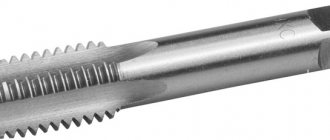
What is what, and most importantly - where. Appearance of the drill and its structure.
- working part - its elements carry out cutting and ensure the correct position of the drill in the hole it creates. The working part of the drill is a cylinder cut by two diametrically opposed helical grooves;
- groove - needed to remove chips from the hole;
- The ribbon is an element for precise direction of the drill and is an additional cutting segment. There are two of them on a typical drill;
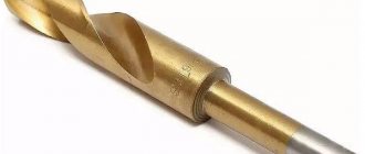
- shank - can be cylindrical or conical, and is used to install the drill into the machine spindle or into the drill chuck;
- back - is the second load-bearing element of the drill after the jumper (more about it below);
- ω is the angle of inclination of the helical groove. The shape of the cutting chips and their removal depend on the value of this angle. For drills with a diameter of 10 - 22 mm, the angle of inclination of the helical groove is ω = 30°; for drills of smaller sizes, this angle is smaller, the smaller the diameter of the drill, and for a diameter of less than 0.25 mm it reaches 19°.
- working cutting edges are the main elements of the drill; when drilling, they form a conical cutting surface;
- jumper - is a continuation of the main cutting edges, it determines the strength and rigidity of the drill;
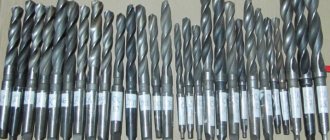
The figure below shows five segment-cutting drills. Two working cutting edges, one transverse edge and two ribbons.
The width of the bands should be sufficient to accurately guide the drill in the hole, but not too wide so as not to cause excessive friction of the drill against the walls of the hole. The larger the diameter of the drill, the wider the ribbon. It is advisable to grind the transverse edge on drills over 3 mm, and it is highly recommended for drill diameters over 18 mm. The wide jumper does not cut, but scrapes and squeezes out the metal, causing the release of additional heat as a result of excessive pressure on the drill. When sharpening the drill correctly, the angle of inclination of the transverse cutting edge ψ should be equal to 55°.
Directly in front of the shank, to increase the strength of the drill, the thickness of the bridge will gradually increase due to a corresponding decrease in the depth of the helical grooves. The surfaces of the helical grooves adjacent to the main cutting edges are the front surfaces of the twist drill, along which the cut chips flow,
The surfaces adjacent to the main edges are the flank surfaces of the drill.
The back angle of the drill is formed by using a tangent to the back surface of the drill. If the rear angles of these cutting edges were equal to zero, then the rear surfaces along their entire length would be in contact with the cutting surface, and large friction would arise between them. The greater the clearance angle, the less friction there is.
The above angle values are achieved by appropriate sharpening of the rear surfaces. The taper of the cutting part of the drill is determined by the angle of 2 φ at its tip, formed by the main cutting edges. The shape of the cutting edge, the front and rear angles, the strength of the drill at the jumper and the cutting force depend on the value of the angle φ.
As the angle φ decreases, the main cutting edge lengthens and heat transfer improves, but the strength of the drill sharply decreases. Recommended angle values of 2 φ depending on the material being processed are shown in the table below.
The main points when working with a drill, which, no matter how hard you try, cannot be avoided:
- Regardless of the drill, whether it is new or not, when drilling begins, not only does a hole form, but the process of dulling the drill itself begins. With each revolution, the drill will plunge slower and slower. With a new drill it will not be so noticeable, but the fact remains;
- the rate of dulling of the drill depends on the speed of its revolutions, the number of revolutions on the cutting surface, the feed rate (pressure on the drill), cooling, the material of the drill and the material being processed;
- maximum heating begins from the periphery of the drill, since the cutting speed is higher there;
- If the drill becomes very dull, it makes a sharp creaking sound during cutting, then heat is released like an avalanche, the wear rate increases and, as a result, the tool becomes unusable. I will tell you how to revive such drills in the next article or video on my channel. Follow the comments.
Rules for drilling metal:
- — the hole must be punched; when starting drilling, you should not put strong pressure on the drill, as you can damage the cutting edges or simply break the drill. The cutting edges should enter the metal smoothly. If you drill with a drill, it is possible for the drill to slip even if it is cored;
- When drilling is completed, at the moment the drill leaves the workpiece, it is necessary to reduce the pressure on the drill. This will help reduce protruding burrs when the drill comes out, and will also prevent the drill from jamming in the workpiece and turning in the chuck;
- the workpiece must be securely fastened, this is a safety precaution and should not be neglected;
- It is prohibited to work with gloves;
- if the required hole is more than 5 mm, then you need to start drilling the part with a small drill, gradually increasing the diameter;
- When drilling metal, it is important not to overheat the drill. For this, special coolants are used; if they are not available, then oil can be used. If it is not possible to use coolant, then the drilling process is carried out intermittently, allowing the drill and the workpiece to cool. You can use a jar of water or oil to dip the drill. Cast iron and non-ferrous metals can be drilled without coolant.
- When drilling deep holes, the length of the cutting part of the tool and the screw grooves must be greater than the depth of the hole. Otherwise, the chip exit will be blocked and the drill will jam. The main attention should be paid to the activity of removing chips from the resulting hole;
- If the drill is jammed in the workpiece, reverse is used to remove it (turn on rotation in the opposite direction).
Continuation of working with the machine and drills:
Sharpening machine JBG-200 and its modification
Drill sharpener from RISS industrie
Drill sharpener - instructions (RISS / CRAFTSMAN 9-6677)
Twist drill: description, application
Both home and professional craftsmen should have many different tools in their arsenal. Drills are indispensable for a whole range of work.
Today there are many varieties of them. However, the twist drill is most widespread. This is due to a number of its features and functions.
The structure of this tool, as well as the scope of its application, deserve special attention.
General information
A drill is a cutting element of a tool that makes holes in various materials. There are many varieties of them. The type of cutter is selected based on the characteristics and working conditions. According to their characteristics, hammer drills and drills must be harder than the material.
The purpose of drills is different. They can be used for processing metal, wood, concrete, glass, and tiles. Each tool has its own characteristics depending on its purpose.
The most widely used today is the twist drill. It is also called screw. It has a cylindrical shape and has a number of design features.
Drill device
A twist drill has three main elements. This is the working part, the shank and neck of the cutter. In the first section there are two spiral helical grooves. This is the cutting element. They also remove chips well from the workplace. If the equipment has this capability, it is through these grooves that the lubricant is supplied to the drilling area.
The working part consists of a cutting and calibrating section. The latter is also called a ribbon. This is a narrow strip that continues the surface of the groove on the cutter. The cutting section consists of two main and two auxiliary edges. They are located along the cutter cylinder in a spiral. This part also includes the transverse edge. It has a cone shape and is located at the end of the drill.
To securely fit into a machine or hand tool, the cutter has a shank. It may have a paw for removing the drill from the socket or a leash. The latter ensures the transmission of torque from the tool chuck.
The neck is needed to release the abrasive wheel when grinding the working part.
Product Features
Drills for hammer drills and machine tools, which have a spiral shape, are the most popular today. This is due to their special characteristics.
They are well aimed in the hole and also have a large margin for regrinding. Due to the design features, such a cutter removes chips well and easily supplies lubricants to the working surface.
These features make this type of drill very popular.
To correctly designate geometric parameters, there are special notations. The diameter of the drill can be very different. However, the designations remain the same. The tip angle at the apex is referred to as 2φ. The inclination of the grooves is denoted by the letter ω, and the end transverse edge is denoted by ψ. The front angle in the drawings is referred to as γ, and the rear angle as α.
Together, these indicators are called drill geometry. It reflects the position of the grooves, cutting edges, as well as their inclination angles.
Types of instruments
The classification of cutters takes into account such an important indicator as the shape of the shank. It can be of the following varieties:
- Milling cutter with a cylindrical shank (GOST 2034-80).
- Drills with a conical shank (GOST 10903).
- Tool with a conical shank (GOST 22736).
To ensure that the master has the opportunity to complete all the tasks assigned to him, the drill is produced in various types. In the first version, the cutter is mounted in a three-jaw chuck or other designated device.
The twist drill with a cylindrical shank can be manufactured in short, medium and long versions. Such a tool has 3 accuracy classes: increased (A1), normal (B1) and normal (B). They can be manufactured either welded or solid. The shank must not have ring cracks, lack of fusion or surface pitting.
Conical varieties are attached directly to the equipment spindle or adapter sleeve (if the size does not match).
Tapered shank
When manufacturing a cutter with a conical shank of the presented type, several different standards are used. The twist drill (GOST 10903) is applicable for products of normal length.
This group also includes several other standards that are used in the process of manufacturing long, elongated cutters. These instruments can be produced with or without a neck.
Moreover, its size is not regulated in any way.
A milling cutter with a conical shank (GOST 22736) regulates the production of products with a diameter of 10-30 mm that have a carbide insert. They can be made in a shortened or normal form. The accuracy class for these products can be increased (A) or normal (B).
Drills with a conical shank with a diameter of more than 6 mm are manufactured by welding. For narrower sections, it is possible to use a one-piece type of manufacturing.
Metal drills
In addition to the breakdown of cutters based on the shank shape, there is a classification regarding the processing material. The cutter can be designed for metal, concrete, there is also a drill for wood. The spiral workbench is suitable for all types of materials. The only difference is in the design of the tool.
Depending on the type of metal, the type of drill is selected. They are applicable for alloyed and non-alloyed steels, cast iron, alloys, and non-ferrous metals. They are sometimes used to process hard plastics. The durability of the product depends on the thickness and hardness of the working area. This is a universal type of tool. A metal drill can fully drill a hole even in wood.
If the tool sinks slowly and heats up the material greatly, it needs to be sharpened. If its diameter does not exceed 12 mm, the procedure is carried out manually. But for larger cutters, special equipment is used for sharpening.
Concrete drill
Concrete is one of the most difficult materials to process. It requires the use of tools with special welded carbide plates. They are usually called pobeditovye. Today, any carbide nozzles are called this way.
In the process of processing the material, such a tool leaves holes with a diameter larger than the drill itself. This is due to its beating. If a drill is used, the drill shank may be cylindrical. For a hammer drill, a different type of fastening is used. It's called SDS. There are several types of them. This system allows you to quickly change attachments in a hammer drill and other equipment.
It is possible to sharpen such drills. However, care should be taken to ensure that the instrument does not overheat. Otherwise, the carbide insert may fall off.
Wood drill
A suitable twist drill bit for wood is made from ordinary high-strength steel. This material does not put forward serious demands on the cutter material or its shape. This is the most ordinary drill. You can quite simply screw a regular self-tapping screw into soft wood or chipboard. You don't need to use a drill for this. However, there are situations where you cannot do without it.
If you need to make a hole up to 600 mm deep, you should use screw-type cutters. Their diameter can be from 8 to 25 mm. Their length may be different. This is convenient if you need to make a blind or through hole. If required, use an extension cord.
When drilling, the drill is removed from the material after several revolutions and cleared of chips. Then they continue working. Their length can be 300, 460 and 600 mm.
Having become familiar with the main characteristics and method of using a tool such as a twist drill, everyone can choose the right type for themselves. This is a very popular type of cutter. Their unique qualities and wide range of applications make them very popular.
Main parts of the drill
Rice. 1 Drill parts
Main parts of the drill.
Cutting part (Fig. 1). Calibrating (guiding, transporting) part. These two parts form the working part of the drill. The connecting part (neck). Tail part.
Working part
together with the cutting and calibrating parts, it forms two helical grooves and two teeth (feathers) that ensure the cutting process.
Calibration part
drills designed to remove chips from the cutting zone. The calibrating part has a ribbon along its entire length and, together with it, serves to guide the drill in the hole.
Neck
For drills, it is used to release the grinding wheel, as well as to mark the drills.
Tail section
It can be cylindrical or conical with a Morse taper. At the end of the tail there is a leash or paw.