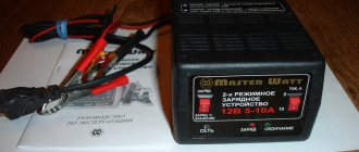
using a thyristor, which even a novice radio amateur can
assemble with his own hands
.
It can be used as a stand-alone device or in addition to an existing charger
, since the circuit implements several types
of protection
.
There is protection
, since without a connected battery there is no output voltage.
Also, the device will not fail if the battery is connected incorrectly; the transistor will open the thyristor only if the battery
.
We take a ready-made transformer or wind it ourselves, with a power of 150-200 watts, a secondary winding with a voltage of 16-19 volts. Instead of the thyristor and transistor indicated in the diagram, you can put KU202 with any letter index and KT815, respectively. Resistor R4 is used to select the minimum charging switch-on voltage; the circuit
is designed for a 12-volt battery. Before turning on, be sure to check the correct installation. I recommend it, an excellent thing against errors.
If desired, you can add a voltmeter and an ammeter at the output of the circuit to the battery. The voltmeter is connected in parallel to the load, and the ammeter in series, through the “+” line.
I recommend making the diode bridge using D242 diodes
Click on image to enlarge
Analogs of thyristor KU 202
Foreign analogues of the KU202N thyristor are VTX32S100, H20T15CN, 1N4202. Foreign manufacturers do not produce devices with the same geometric dimensions as the KU202N, so you will need to change the location for mounting the device. It should also be taken into account that their parameters may differ slightly from the thyristor in question, for example, the average current may be 7.5 A.
In addition to foreign devices, you can use the Russian analogue - T112-10. Like KU202N, it has a metal body and an anode outlet for thread. However, its dimensions are smaller, so the installation location will still have to be changed.
Schematic and printed circuit board of the SCR memory
The printed circuit board is drawn by hand with a marker. You can make the wiring yourself, for example based on this picture:
Parameters of thyristor KU 202
| Parameter | Designation | Unit | Thyristor type | |||
| KU202A | KU202B | KU202V | KU202G | |||
| Constant current in closed state | Iz. With | mA | 10 | 10 | 10 | 10 |
| Constant reverse current at Urev max | Iobr | mA | 10 | 10 | 10 | 10 |
| Unlocking constant control current | Iу. from | mA | 200 | 200 | 200 | 200 |
| Unlocking constant control voltage | Uу. from | IN | 7 | 7 | 7 | 7 |
| Open voltage | Uoc | IN | 1,5 | 1,5 | 1,5 | 1,5 |
| Non-latching constant control voltage | Uу. notes | IN | 0,2 | 0,2 | 0,2 | 0,2 |
| On time | ton | mks | 10 | 10 | 10 | 10 |
| Shutdown time | toff | mks | 150 | 150 | 150 | 150 |
| Maximum permissible parameters | ||||||
| Constant voltage when closed | Uz. with max | IN | 25 | 25 | 50 | 50 |
| Constant reverse voltage | Uar max | IN | — | — | — | — |
| Constant reverse control voltage | Uу. arr max | IN | 10 | 10 | 10 | 10 |
| Minimum forward voltage in closed state | Uz. with min | IN | — | — | — | — |
| Constant current in open state | Ioc min | A | 10 | 10 | 10 | 10 |
| Pulse current in open state | Ios. and min | A | 50 | 50 | 50 | 50 |
| Constant forward control current | Iу max | A | — | — | — | — |
| Pulse dissipated power of the UE | Ru. and max | W | — | — | — | — |
| Average power dissipation | Pav max | W | 20 | 20 | 20 | 20 |
| Maximum ambient temperature | Tmax | °C | +85 | +85 | +85 | +85 |
| Minimum ambient temperature | Tmin | °C | -60 | -60 | -60 | -60 |
| Parameter | Designation | Unit | Thyristor type | |||
| KU202D | KU202E | KU202ZH | KU202I | |||
| Constant current in closed state | Iz. With | mA | 10 | 10 | 10 | 10 |
| Constant reverse current at Urev max | Iobr | mA | 10 | 10 | 10 | 10 |
| Unlocking constant control current | Iу. from | mA | 200 | 200 | 200 | 200 |
| Unlocking constant control voltage | Uу. from | IN | 7 | 7 | 7 | 7 |
| Open voltage | Uoc | IN | 1,5 | 1,5 | 1,5 | 1,5 |
| Non-latching constant control voltage | Uу. notes | IN | 0,2 | 0,2 | 0,2 | 0,2 |
| On time | ton | mks | 10 | 10 | 10 | 10 |
| Shutdown time | toff | mks | 150 | 150 | 150 | 150 |
| Maximum permissible parameters | ||||||
| Constant voltage when closed | Uz. with max | IN | 120 | 120 | 10 | 10 |
| Constant reverse voltage | Uar max | IN | — | — | 240 | 240 |
| Constant reverse control voltage | Uу. arr max | IN | 10 | 10 | — | — |
| Minimum forward voltage in closed state | Uz. with min | IN | — | — | — | — |
| Constant current in open state | Ioc min | A | 10 | 10 | 10 | 10 |
| Pulse current in open state | Ios. and min | A | 50 | 50 | 50 | 50 |
| Constant forward control current | Iу max | A | — | — | — | — |
| Pulse dissipated power of the UE | Ru. and max | W | — | — | — | — |
| Average power dissipation | Pav max | W | 20 | 20 | 20 | 20 |
| Maximum ambient temperature | Tmax | °C | +85 | +85 | +85 | +85 |
| Minimum ambient temperature | Tmin | °C | -60 | -60 | -60 | -60 |
| Parameter | Designation | Unit | Thyristor type | |||
| KU202K | KU202L | KU202M | KU202N | |||
| Constant current in closed state | Iz. With | mA | 10 | 10 | 10 | 10 |
| Constant reverse current at Urev max | Iobr | mA | 10 | 10 | 10 | 10 |
| Unlocking constant control current | Iу. from | mA | 200 | 200 | 200 | 200 |
| Unlocking constant control voltage | Uу. from | IN | 7 | 7 | 7 | 7 |
| Open voltage | Uoc | IN | 1,5 | 1,5 | 1,5 | 1,5 |
| Non-latching constant control voltage | Uу. notes | IN | 0,2 | 0,2 | 0,2 | 0,2 |
| On time | ton | mks | 10 | 10 | 10 | 10 |
| Shutdown time | toff | mks | 150 | 150 | 150 | 150 |
| Maximum permissible parameters | ||||||
| Constant voltage when closed | Uz. with max | IN | 10 | 10 | 10 | 10 |
| Constant reverse voltage | Uar max | IN | 360 | 360 | 480 | 480 |
| Constant reverse control voltage | Uу. arr max | IN | — | — | — | — |
| Minimum forward voltage in closed state | Uz. with min | IN | — | — | — | — |
| Constant current in open state | Ioc min | A | 10 | 10 | 10 | 10 |
| Pulse current in open state | Ios. and min | A | 50 | 50 | 50 | 50 |
| Constant forward control current | Iу max | A | — | — | — | — |
| Pulse dissipated power of the UE | Ru. and max | W | — | — | — | — |
| Average power dissipation | Pav max | W | 20 | 20 | 20 | 20 |
| Maximum ambient temperature | Tmax | °C | +85 | +85 | +85 | +85 |
| Minimum ambient temperature | Tmin | °C | -60 | -60 | -60 | -60 |
Phase voltage regulation
There are several ways to regulate alternating voltage with thyristors: you can pass or inhibit entire half-cycles (or periods) of alternating voltage from the regulator output. And you can turn it on not at the beginning of the half-cycle of the mains voltage, but with some delay - 'a'. During this time, the voltage at the regulator output will be zero, and no power will be transferred to the output. The second part of the half-cycle the thyristor will conduct current and the input voltage will appear at the output of the regulator.
The delay time is also often called the opening angle of the thyristor, and so at zero angle, almost all the voltage from the input will go to the output, only the drop across the open thyristor will be lost. As the angle increases, the thyristor voltage regulator will reduce the output voltage.
The regulating characteristic of a thyristor converter when operating on an active load is shown in the following figure. At an angle of 90 electrical degrees, the output will be half the input voltage, and at an angle of 180 electrical degrees. the output degrees will be zero.
Based on the principles of phase voltage regulation, it is possible to construct regulation, stabilization, and soft start circuits. For a smooth start, the voltage must be increased gradually from zero to the maximum value. Thus, the opening angle of the thyristor should vary from the maximum value to zero.
DIY thyristor charger
Homemade thyristor
To assemble the presented circuit yourself, you will need a minimum of time and effort, along with low costs for components. Most of the components can be easily replaced with analogues. Some parts can be borrowed from failed electrical equipment. Before use, the components should be checked, thanks to this, a charger assembled even from used parts will work immediately after assembly.
Unlike models on the market, the performance of a self-assembled charger is maintained over a larger range. You can charge a car battery from -350C to 350C. This and the ability to regulate the output current, giving the battery a large amperage, allows in a short time to compensate the battery for a charge sufficient to turn the starter on the engine.
Thyristor chargers have a place in car enthusiasts' garages due to their ability to safely charge a car battery. The schematic diagram of this device allows you to assemble it yourself using products from the radio market. If knowledge is not enough, you can use the services of radio amateurs who, for a fee that is several times less than the cost of a store-bought charger, will be able to assemble the device for you according to the diagram provided to them.
How to make a memory yourself?
If we talk about producing a charger with our own hands, then we will consider this process using the example of circuit 2. In this case, thyristor control is carried out through a phase shift. We will not describe the entire process, since it is individual in each case, depending on the addition of additional components to the design. Below we will consider the main nuances that should be taken into account.
In our case, the device is assembled on ordinary hardboard, including the capacitor:
- The diode elements, marked in the diagram as VD1 and VD 2, as well as thyristors VS1 and VS2, should be installed on the heat sink; installation of the latter is allowed on a common heat sink.
- Resistance elements R2, as well as R5, should be used at least 2 watts each.
- As for the transformer, you can purchase it in a store or take it from a soldering station (high-quality transformers can be found in old Soviet soldering irons). You can rewind the secondary wire to a new one with a cross-section of about 1.8 mm at 14 volts. In principle, thinner wires can be used, since this power will be enough.
- When you have all the elements in your hands, the entire structure can be installed in one housing. For example, you can take an old oscilloscope for this. In this case, we will not make any recommendations, since the body is a personal matter for everyone.
- After the charger is ready, you need to check its functionality. If you have doubts about the build quality, we would recommend diagnosing the device on an older battery, which you wouldn’t mind throwing away if something happens. But if you did everything correctly, in accordance with the diagram, then there should be no problems in terms of operation. Please also keep in mind that the manufactured memory does not need to be configured; it should initially work correctly.
A simple thyristor charger in an oscilloscope housing
Design features of welding transformers
The current of the welding transformer is regulated in various ways. Currently the most used of them are:
When a magnetic shunt is introduced into the magnetic circuit of a transformer, part of the magnetic flux created by the primary winding is removed by the magnetic shunt and therefore this part of the magnetic flux bypasses the secondary winding. In this case, the efficiency of energy transfer from the primary winding to the secondary winding decreases and, as a result, the welding current decreases. In the second method, when the windings are separated, their magnetic coupling deteriorates and the efficiency of energy transfer from the primary winding to the secondary winding decreases. As a result, the welding current is reduced. Both of these methods provide smooth control of the welding current. Moreover, due to the constant number of turns of the windings, the no-load voltage of the transformer remains unchanged. Welding transformers of this type provide incident V-V characteristics and are thus suitable for manual arc welding with covered electrodes.
Brief historical background on the development of power sources for arc welding.
| Welding power source type | Since what year has it been used (approximately) |
| Welding converter (electric motor + generator) | ≈ 1905 |
Transformer | ≈ 1920 |
| ≈ 1950 |
Welding thyristor rectifier | ≈ 1970 |
Welding inverter | ≈ 1980 |
Arc welding power supplies provide electrical energy to the welding process. At the same time, they have a significant impact on the nature of the welding process (primarily on quality and productivity). Therefore, a deeper understanding of the properties of power sources and the principles of their operation is mandatory for those who intend to work in the field of welding (although, of course, the following brief classification of power sources and a somewhat simplified discussion of their properties does not imply complete information on this issue).
